Creating Architectural and Structural model with 3D rendering using REVIT
Question 1) Select the type of structure you want to build from one of the three below:
a. Multi-Unit Residential Apartment
b. Office Buildings
c. School
Answer.For this project I am drawing a School building.
Question 2) Assume reasonable assumptions for geographic and location details for your project modeling. Based on assumptions and type of structure selected identify the modeling requirements from NBC.
Answer. There are some general requirements for the School building. I proposed to design a School in Uttar Pradesh,Aligarh:
- Type of the building: School building.
- The building should be of south facing, in order to get the proper sunlight which can enter the room easily.
- Minimum area for the class room: 600 sq ft.
- The level of the school should be high so that the water-logging should not take place.
- Zone: Zone 1.
These are the some assumptions for the planning of the building accordint to the NCB.
Question 3) Using the structural model, include the following components based on the type of structure selected
a. Foundation – Isolated / Wall/Matt Foundation
b. Columns
c. Beams Connected to Columns
d. Roof Framing/ Truss
e. Floor / Decks
f. Floor Openings for Elevators and Stairs.
AIM: To create the structural model,including the components like Foundation,Column,Beams connected to column,Roof framing or truss,Floor/Decks,Floor opening.
INTRODUCTION: In this question we will be able to learn about the different components in the structural template like columns,beams,roof,floor etc. So lets get started.
PROCEDURE:
- First of all we have to plan a foundation layout.
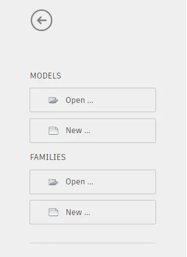
- In order to create the foundation layout open the Revit software, Click on the New option from the home page as shown in the below figure:
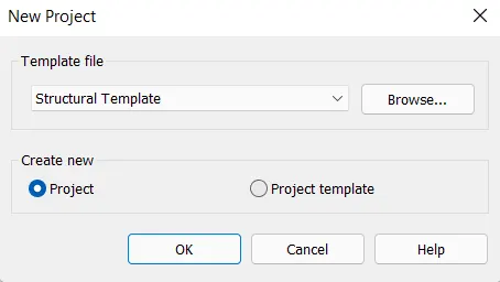
- After clicking the New option new dialouge box appears on the screen titles as the New Project fron that dialouge box in the
Template file search for the Structural Template and then press OK as shown in the below figure:
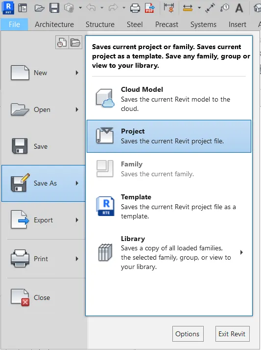
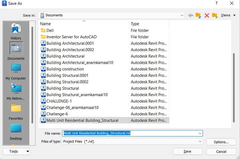
- After clicking OK in the New project dialouge box a new drawing screen appears after that just go to the File tab from there select Save As option type the File name and save it. Here the file name is "Multi-Unit Residential Apartment building_Structual". As shown in the below figure:
- After saving the file. Create the grids and the levels.
- To create the grid go to the Project browser select the Elevation option and in that box select the East and the create the grids on the Elevation Part.
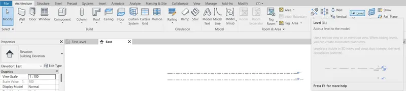
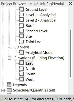
- As shown in the below figure

- After creating the Levels now create the grids as shown in the below figure:
(a) Foundation:
- So in order to create the foundation layout.
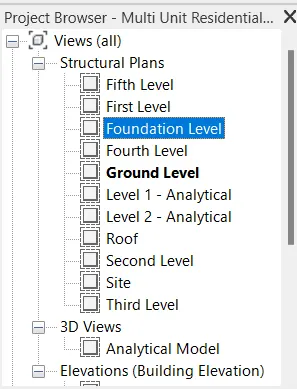
- Just go to the Project browser click on the Fondation level in order to draw the foundation of the plan as shown in the below figure:
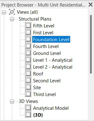
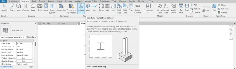
- After that just click on the Structural tab and from that tab just click on the Isolated tab as shown below:
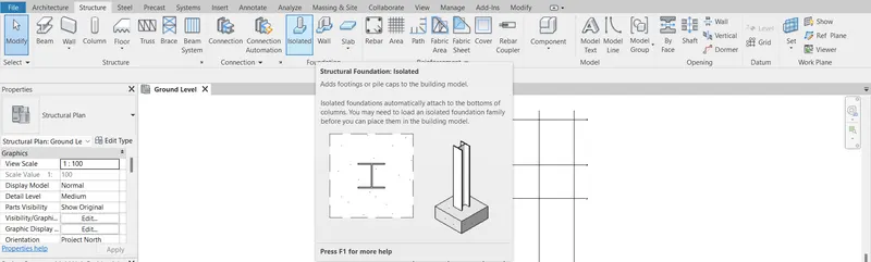
- After clicking on the Isolated option in the Structural tab,choose the foundation size from the properties option as shown in the below figure:
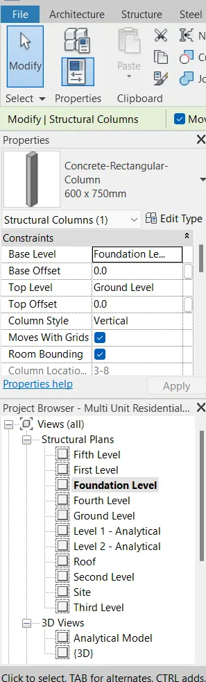
- And then click on the option At grid and select all the grid lines as given below:
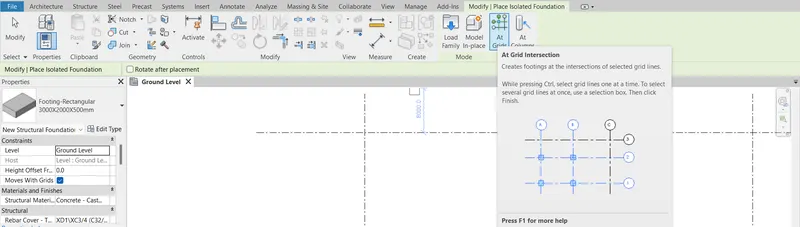
- After selecting the grids click on the Finish button as shown in the below figure:

- After the selection the foundation is placed automatically on the grid lines.
- And this is the 3D image of the foundation:
(b) Columns:
PROCEDURE:
- In order to create the column in the plan.
- Just go to the structural Tab there is an option Column click on that option as shown in the below figure:
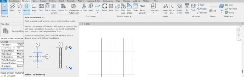
- After clicking the column option Choose the column size from the property browser.
- After choosing the size click on the option At grid and select the whole grids and then column will be automatically placed on the grid.
- After selecting the grids click on the Finish button as shown in the below figure:
- After that click on the finish button now columns are placed at there respective places as shown in the below figure:
- And this is the 3D image of the column:
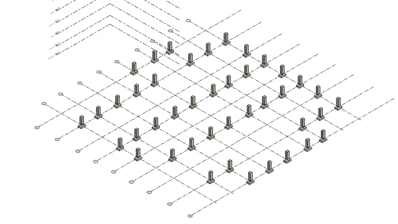
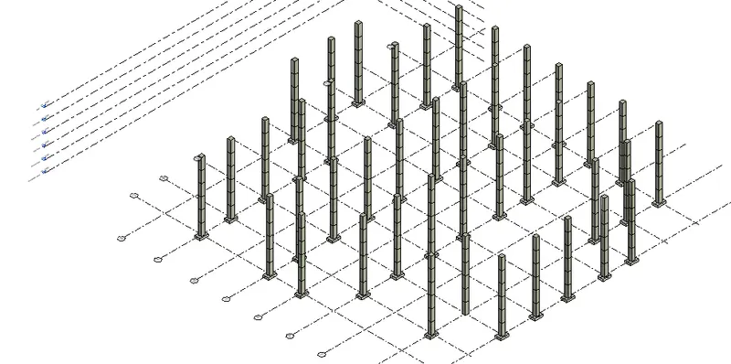
(c) Beams Connected to Columns:
PROCEDURE:
-In order to create the beams that are connected to the columns we need to go to the Structural tab,in that tab there is an option called column. Click on that option,as shown in the below figure:
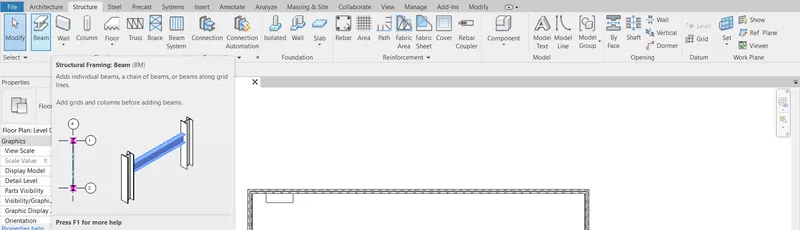
- After clicking on the option beam. And then draw the beams manually according to the plan just as shown in the below figure:
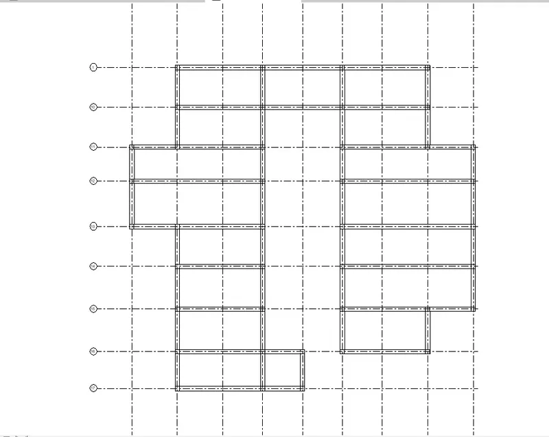
- Here below is the 3D image of the beams that are connected to the columns:
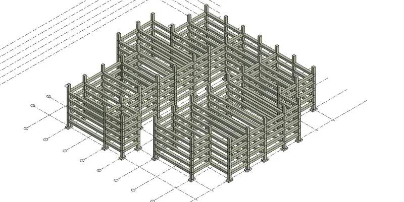
- Now beams connected to columns have been placed in the drawing.
- Further moving on we have to draw the Roof or the truss.
- So as i want to sketch a roof on my plan so i decided not to draw the truss. So here is the detailed procedure in order to create Roof.
(d) Roof Framing/ Truss:
PROCEDURE:
- To create a roof on our plan first of all we have to go to the Structural tab from there only we have the another option called Roof, as shown in the below figure :
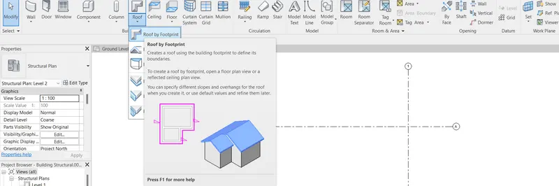
- After clicking on that option another tab opens named Modify,in that section only we have to choose the boundary by using the desired tool like by using the line option or rectangle or polygon or pick lines or many more just click on that option which is more suitable. For this project i have used the Rectangle option. So just click on the Rectangle option and then just draw the rectangle in the desired place where you want to create a roof in a drawing just as shown in the below figure:
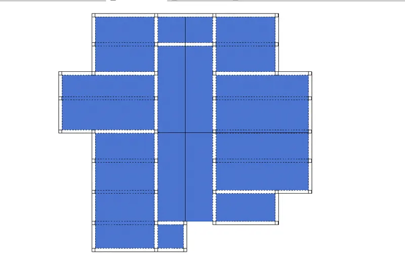
- The selected area in the above picture is the selected area for the roof.
- Now given below image is the 3D image for the roof :
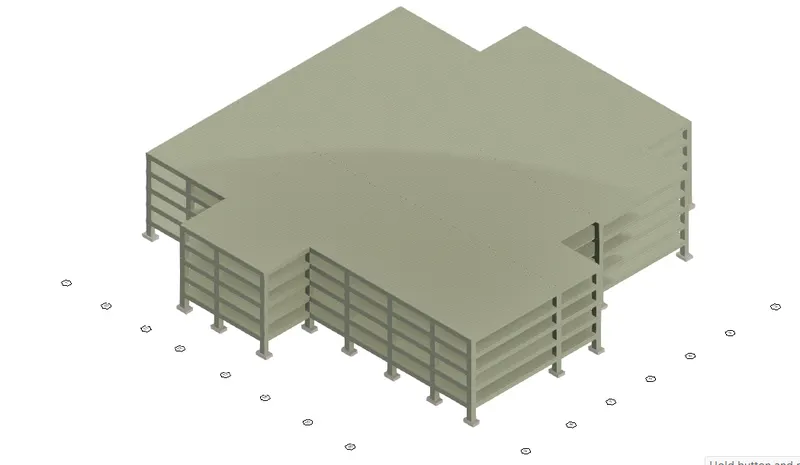
- The floor is ready. After floor we need to create a floor opening or hafts for the staircase or the lifts. In order to get the floor opening we need to know the procedure in detail. So below is the detailed procedure for creating the shafts.
(f) Floor Openings for Elevators and Stairs:
PROCEDURE:
- So in order to create the shafts we need to go to the Structural tab,from there tab we need to click on the option Shaft so here is the below image showning how we can or where we can use the option Shaft in the drawing:
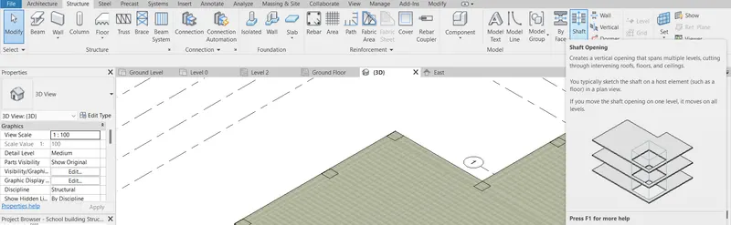
- After clicking on that option another tab opens named Modify| Create Shaft Opening Sketch,in that section only we have to choose the boundary by using the desired tool like by using the line option or rectangle or polygon or pick lines or many more just click on that option which is more suitable. For this project i have used the Rectangle option. So just click on the Rectangle option and then just draw the rectangle in the desired place where you want to create a shaft in a drawing just as shown in the below figure:

Question 4) Using the architectural model, include the following components based on the type of structure selected
a. Wall Layout with appropriate material and finishing
b. Exterior façade with fancy finish
c. Interior partition walls to size rooms
d. Components to add details to a room ( Desk, Chair, Lighting, Plumbing fixtures)
e. Add components such as stairs Elevators
f. Have at-least one side of the building with curtain walls and glass panels
g. Include interior and exterior lighting fixtures
h. Place proper topographic components from outside ( Trees, Parking, Plants) to add details to the model.
AIM: To include the different components using the architectural model based on the type of structure in this project.
INTRODUCTION: Revit software allows the user to create the 3D model,elevation,section,rendering amd many other architectural components. So in this question we will be able to understand the project in an architectural aspects. Like the rendering of the project,aesthetic views,planning,creating furnishing and many more.
PROCEDURE:
- So in order to go to the Architectural template,first of all we need to open the Revit 2023 software. In the home page we found an option called New so there click on the option in order to get the New project,as seen in the below figure:
- After clicking the New option new dialouge box appears on the screen titles as the New Project fron that dialouge box in the
Template file search for the ArchitecturalTemplate and then press OK as shown in the below figure:
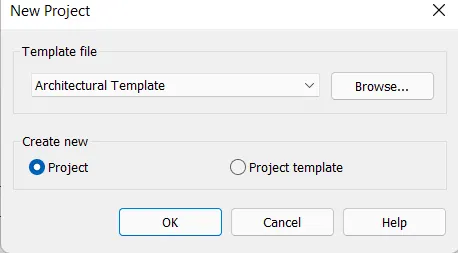
- After clicking OK in the New project dialouge box a new drawing screen appears after that just go to the File tab from there select Save As option type the File name and save it. Here the file name is "School building_Architectural". As shown in the below figure:
- After saving the file. Create the grids and the levels.
- To create the grid go to the Project browser select the Elevation option and in that box select the East and the create the grids on the Elevation Part.
(a) Wall Layout with appropriate material and finishing:
PROCEDURE:
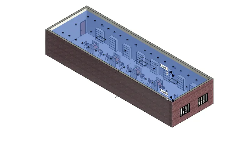
- In order to create the wall layout with appropriate material and finishing we first need to draw the layout of our plan like as shown in the below figure:
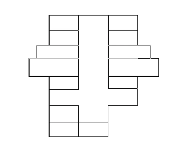
- After creating the layout we can manage the walls material either with the help of the properties option or from the Edit type option as just shown in the below figure:
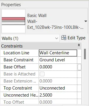
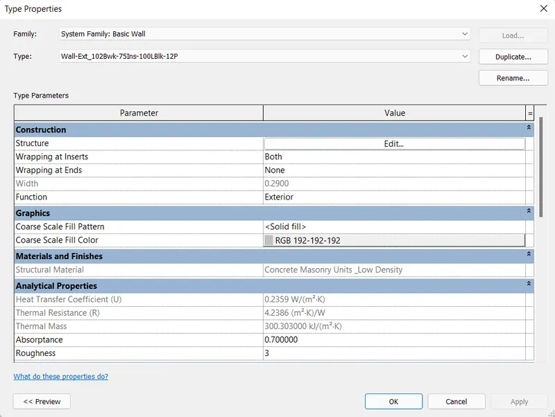
- In either way we can change the properties of the wall like the thickness of the wall,material of the wall,height of the wall and many other properties we can manage using these dialouge box.
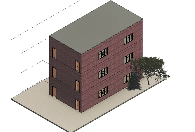
- Like the above image i used the image of only 1 classroom. The above image is the 3D image of only one classroom.
- So this is how we can manage the wall material and many other properties.
(b) Exterior façade with fancy finish:
PROCEDURE:
- Below is the image to show the exterior facade with the fancy finish of the wall,we can get the exterior facade with fancy finish we need to go to the properties browser. There are multiple options of createing the fancy,aesthetic and pleasing to the eyes view or facade. From there we can choose the multiple materials that we need to wish insert in our project as shown in the below figure:
- After clicking on the option Edit Type,a new dialouge box opens named Type property in that box click on the option Structure and then click on the Edit option as shown in the below figure:
- After clicking the Edit option we will see a new dialouge box appears on the structure named Edit assembly, from there we need to click on the material option as shown in the below figure:
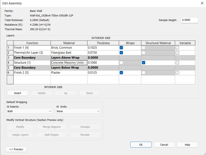
- Again a new dialouge box opens up as we click on the option Edit, in that dialouge box we have many option to give a fancy finish to our walls or facade or the floor etc,as shown in the below figure:
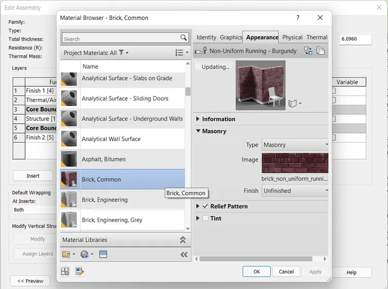
- Now this is how we can change the properties of the walls.
- Here is the image showing the Exterior facade with fancy finish:
(c) Interior partition walls to size rooms:
PROCEDURE:
- The interior partition walls to size the rooms.
- Actually in interior walls of the buiding is somewhat smaller in terms of their thickness, we mostly provide 0.12m thick wall for partitioning the inner wall.
- So here is the image of the inner walls or the partition walls:
- The inner walls of this layout is the partition wall to create the different sizes of the room.
- Here is the 3D structure of the partition wall to understand the concept of partition wall,so here we go the below image is the partition wall for the building:
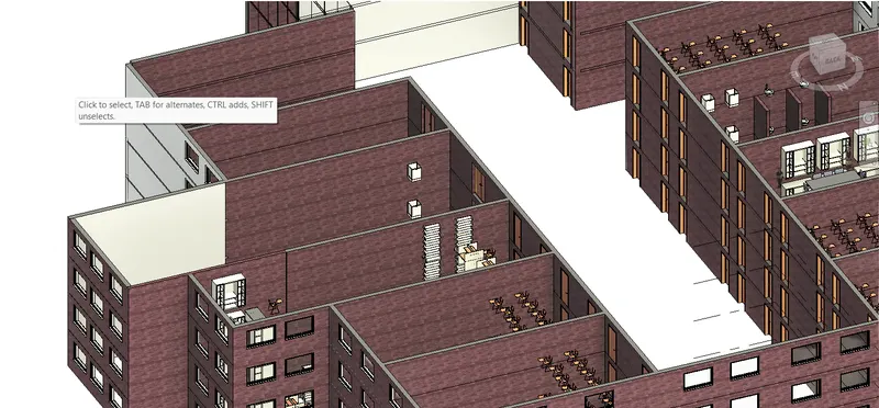
- The above picture is the 3D image showing the partitions walls. The walls separating the rooms are called as the interior walls or you can say Partition Walls.
(d) Components to add details to a room ( Desk, Chair, Lighting, Plumbing fixtures):
- So in order to add the detailing of components like desk,chair lightning,plumbing fixtures etc
- We need to go to the insert tab from there we have to click on the option Load Family in that option we have plenty of components which we can use to furnish our house and other things as shown in the below image:

- After that a new dialouge box opens named Load Family in that box click on the option US. Just like shown in the below figure:
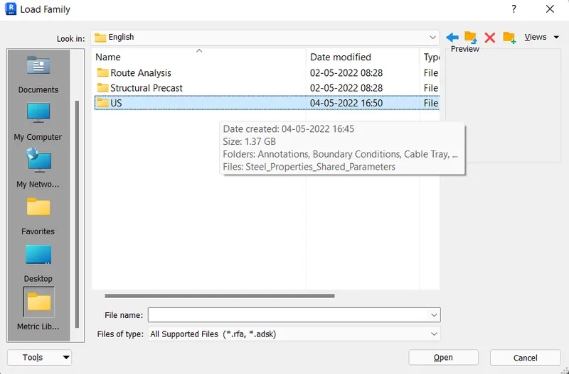
- Click on the option US and then a new dialouge box opens from there we can choose the different components and can furnish our plan as we desired here is the image showing the different families and their components:
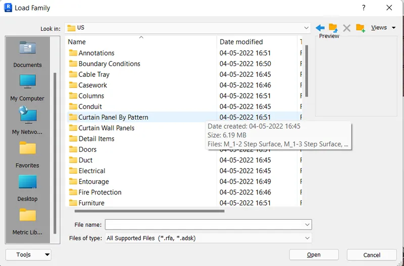
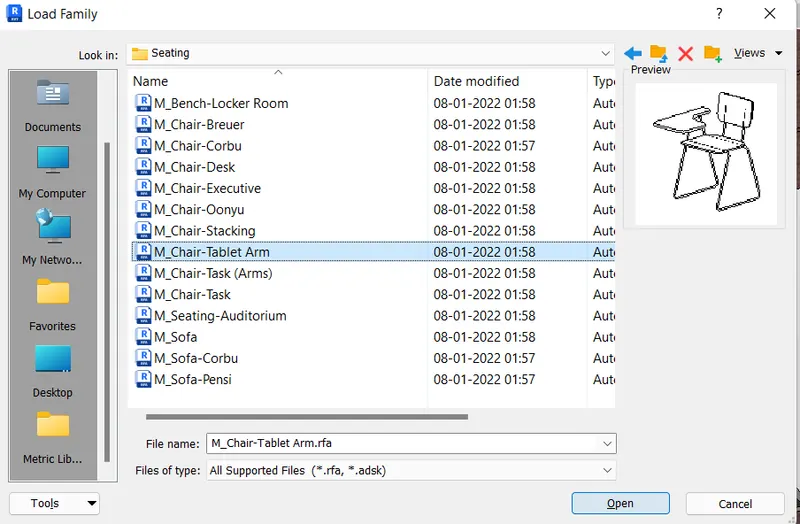
- These are the different components that you will need to furnish your project. So after selecting the desired component just go to the Architectural tab and from there go to the option Components click on that option and there is another option called Place a Component.
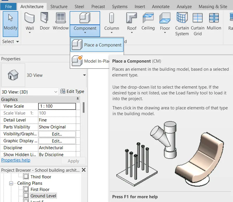
- After clicking on that option just place the component at the desired place in your project. Do the same procedure forf placing the different components at the different places.
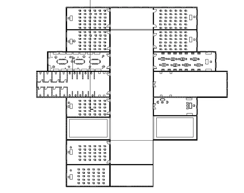
- The below image shows the different components in my plan :
(e) Add components such as stairs Elevators:
PROCEDURE:
- In order to create the staircase first of all we need to go th e Architectural tab in that tab there is an option called Stairs just click on that option as shown in the below figure:
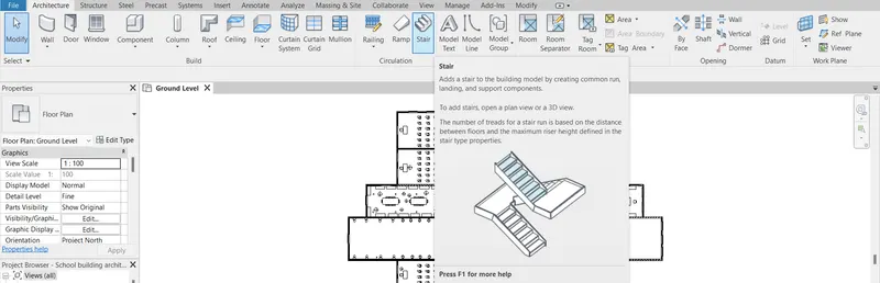
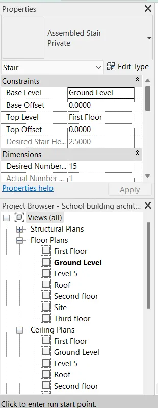
- After clicking on that option another tab opens named Modify|Create Stairs,in that section only we have to choose the boundary by using the desired tool like by using the line option or rectangle or polygon or pick lines or many more just click on that option which is more suitable. For this project i have used the Rectangle option. So just click on the Rectangle option and then just draw the rectangle in the desired place where you want to create a stair in a drawing just as shown in the below figure:

-After creating the stairs adjust the riser depth,thickness and the other properties according to the project or we can say that according to the requirement for the staircase as shown in the below figure:
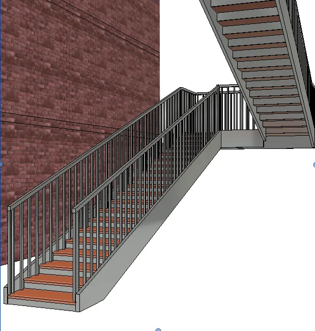
-After doing the all sort of arrangements for the staircase,now the staircase is ready as shown in the below figure:
(f)Have at-least one side of the building with curtain walls and glass panels:
PROCEDURE:
- So to create the curtain walls and glass pannels we have option in the Architectural tab. To use that option just go to the Architectural tab and in that tab there are multiple options and from that options there is an option called Curtains. Just click on that option to create the curtain walls as shown in the below figure :
(g) Include interior and exterior lighting fixtures:
PROCEDURE:
- Now we have to give the lighting fixture in the plan. So for doing so first of all we need to create a ceiling on that floor which we want to give the light fixture.
- So for doing so we need to go to the Architectural tab there is an option called Ceiling. Click on that option as shown in the below figure:

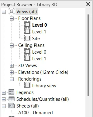
: And to create a ceiling we need a ceiling plan. So just go to the Project Browser option,search for the Ceiling plan in that option there are another options like Ground floor,first floor,second floor etc. So first we need to fix the lightning fixture in the ground floor. So in order to create the ceiling on the ground floor click on the ceiling plan. And click on the ceiling plan in the Architectural tab as shown in the below figure:
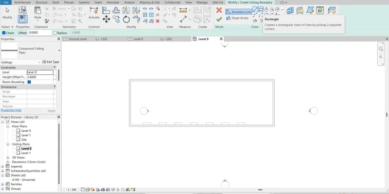
- After that we need to create the ceiling using modify tools .- After clicking on that option another tab opens named Modify,in that section only we have to choose the boundary by using the desired tool like by using the line option or rectangle or polygon or pick lines or many more just click on that option which is more suitable. For this project i have used the Rectangle option. So just click on the Rectangle option and then just draw the rectangle in the desired place where you want to create a ceiling in a drawing just as shown in the below figure:

- Now the ceiling have been created in the existing plan after created the ceiling we need to provide the lightning fixture to that particular floor.
- In order to do that we firstly need to go to the Insert tab in that tab there is an option called Load family.
- In that option we have plenty of components which we can use to furnish our house and other things as shown in the below image:
- After that a new dialouge box opens named Load Family in that box click on the option US. Just like shown in the below figure:
- Click on the option US and then a new dialouge box opens from there we can choose the different components and can furnish our plan as we desired here is the image showing the different families and their components:
- These are the different components that you will need to furnish your project. So after selecting the desired component just go to the Architectural tab and from there go to the option Components click on that option and there is another option called Place a Component.
- After clicking on that option just place the component at the desired place in your project. Do the same procedure forf placing the different components at the different places.
- The below image shows the different components in my plan :
(h) Place proper topographic components from outside ( Trees, Parking, Plants) to add details to the model
PROCEDURE:
- In order to do that we firstly need to go to the Insert tab in that tab there is an option called Load family.
- In that option we have plenty of components which we can use to furnish our house and other things as shown in the below image:
- After that a new dialouge box opens named Load Family in that box click on the option US. Just like shown in the below figure:
- Click on the option US and then a new dialouge box opens from there we can choose the different components and can furnish our plan as we desired here is the image showing the different families and their components:
- These are the different components that you will need to furnish your project. So after selecting the desired component just go to the Architectural tab and from there go to the option Components click on that option and there is another option called Place a Component.
- The below image shows the different components in my plan :
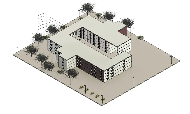
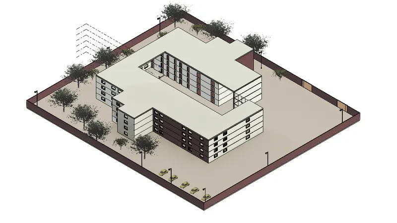
Question 5) Provide a set of drawings in an architectural and structural model to list the following details with categories and appropriate sheet templates included
a. Floor Plans with Annotations
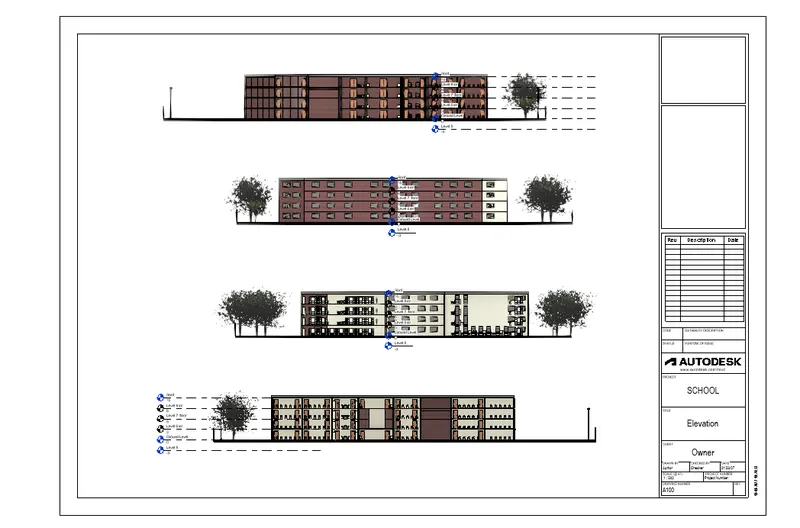
b. Elevations
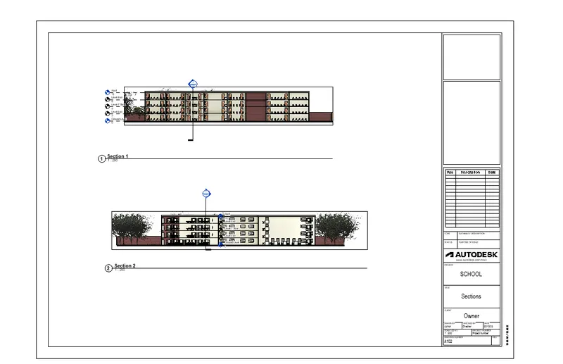
c. Sections.
AIM: To provide a set of drawings in an architectural and structural model to list the following details with categories and appropriate sheet templates included
a. Floor Plans with Annotations.
b. Elevations.
c. Sections.
INTRODUCTION: Revit software allows the user to create their own appropriate sheet template according to their desire or requirement. Here in this question we will be studying or learning thoroughly about the sheet templates. So below is the detailed procedure and the explination regarding sheet template.
PROCEDURE:
(a) Floor Plans with Annotations:
- In order to create the sheet template. Firstly we have to go to the view tab. From there choose option Sheet as shown in the below figure:

- After clicking on the sheet option a new dialouge box opens named New Sheet, in that dialouge box click on the load option and after doing so we will be able to get different sheets with different sizes. So choose the size if your cheet and then click ok as shown in the below figure:
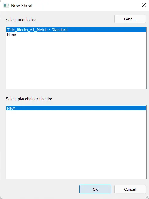
- After this a new sheet of the choosen size appears on the screen as shown below:
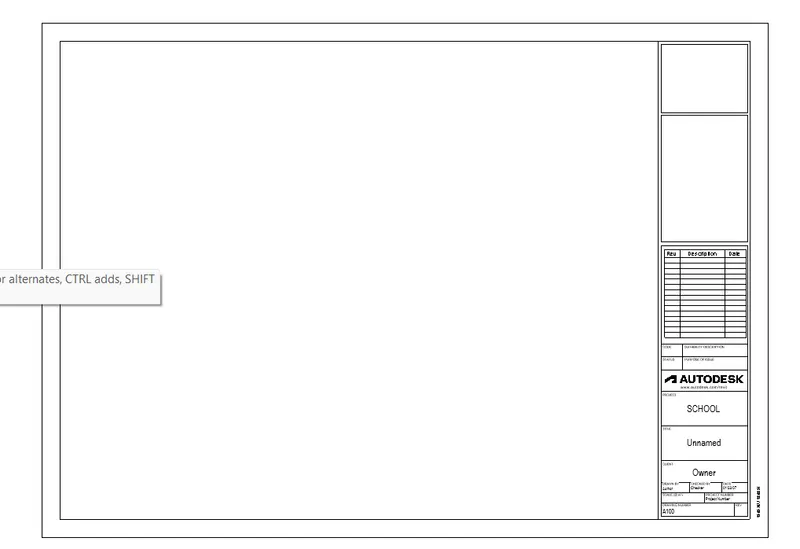
- And to edit the details on the sheet go to the project browser right click on the sheet and then click on the option rename from that and edit the changes click OK. After clicking OK the edit content appears on the sheet.
- After doing this drag the desired file into the sheet and release them in the sheet.
- And if the size of the file is too big adjust the scale of the file using the file browser as shown in the below image:
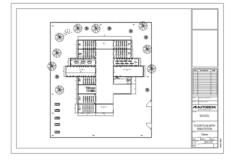
- Now do the same procedure for all the sheets as we discussed above.
(b) Elevations:
(c) Sections:
Question 6) Using the Rendering settings, Render images of the 3D model produced and include the rendered images to the drawing sheets
a. Rendering from interior rooms
b. Rendering from out showing topographic features
c. Rendering through structural framing.
AIM: Using the Rendering settings, Render images of the 3D model produced and include the rendered images to the drawing sheets
a. Rendering from interior rooms.
b. Rendering from out showing topographic features.
c. Rendering through structural framing.
INTRODUCTION: Revit software allows the user to create a Rendered model with high quality. So in order to learn the procedure of using the Rendering of different rooms and parts of the building we will be learning here in this question. So here is the detailed procedure and the explanation of the procedure how to use the rendering in the Revit structure.
PROCEDURE:
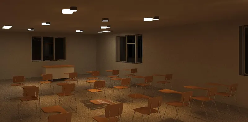
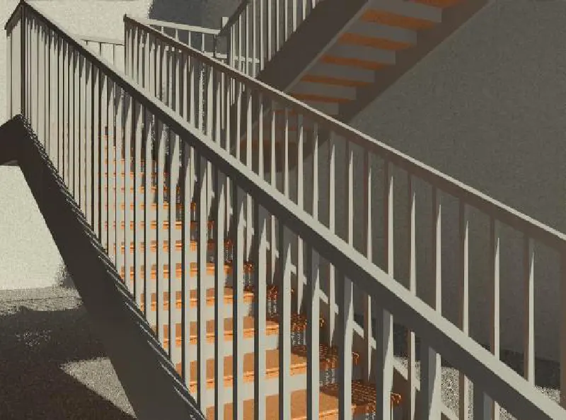
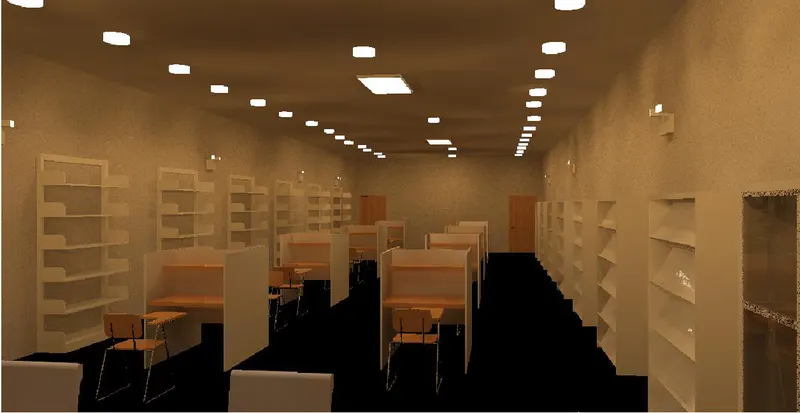
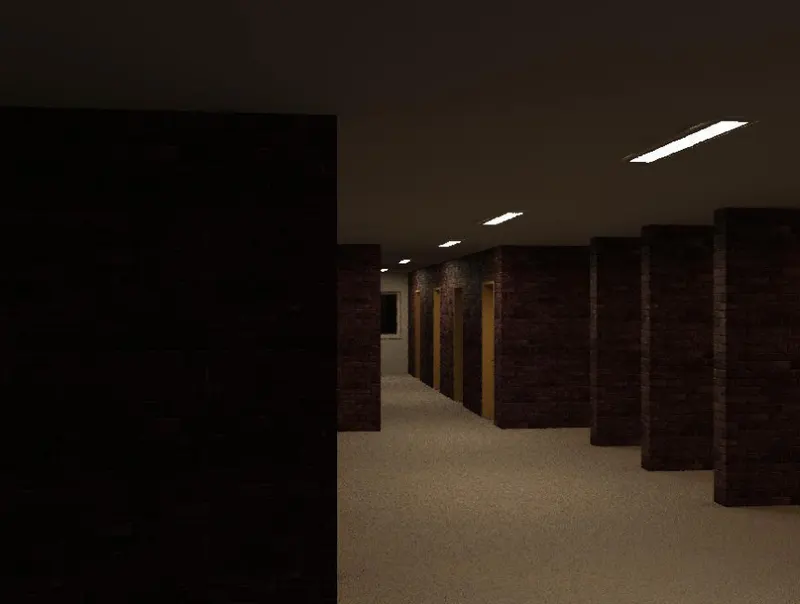
(a) Rendering from interior rooms:
i. Class Room:
ii. Staircase:
iii. Library:
iv. Boys Washroom:
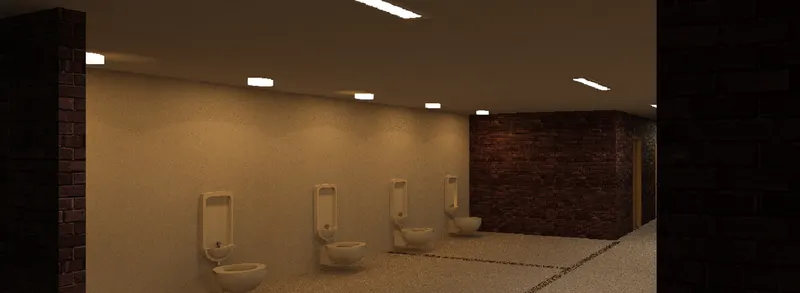
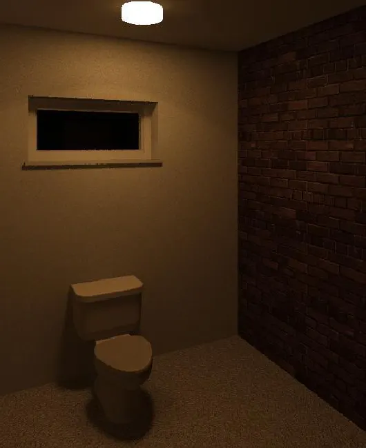
v. Girls Bathroom:
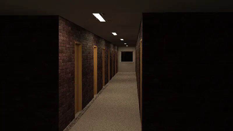
v. Principals Office:
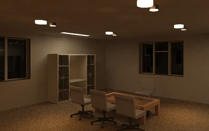
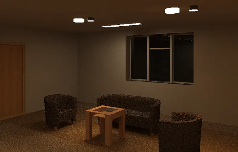
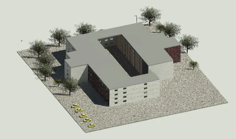
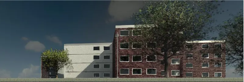
b. Rendering from out showing topographic features:
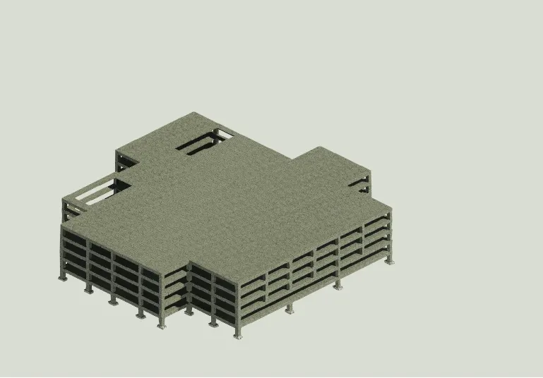
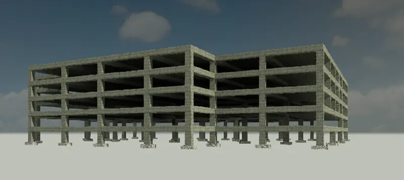
(c) Rendering through structural framing:
Question 7) Print the set of drawing sheets created and submit the drawings from the architecture and structure model.
AIM: To print the set of drawing sheets created and submit the drawings from the architecture and structure model.
INTRODUCTION: In revit software we can manage to print the sheets that we draw on the Revit software. Here we can learn about the print option in the Revit software. Here are the detailed procedure as discussed.
PROCEDURE:
- In order to print the sheets in the Revit software. Press the Control + P after pressing the keys the new dialouge box appears on the screen. As shown in the below figure:
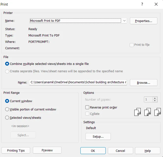
- In this dialouge box just click on the option Selected Views/sheets. After clicking on that option new window appears on the screen as shown in the below figure:
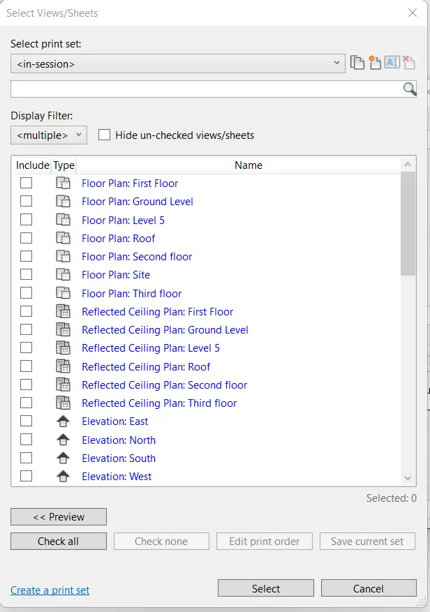
- From the above window select the desired sheet which we want to print then click the option Select and then press OK.
- Set the print file name and save it as print to pdf and click OK.
- In this way we can print the sheets.