Creating a Wardrobe detailed drawing, Floor Plan, Kitchen Layout and Column Detail using AutoCad
1) ELEVATION AND DETAILS OF A WARDROBE
AIM: To create the elevation and details of a wardrobe using AutoCAD.
INTRODUCTION: The elevation and details of a wardrobe using AutoCAD is created by Lines and Circles. The procedure and result should be written after creating the elevation and details of a wardrobe.
PROCEDURE:
(a)PLAN
STEP 1:
- Open the AutoCAD software and click start Drawing tab.
- Enter UNITS in command box.
- Select DECIMAL in TYPE, 0 in PRECISION and MILLIMETERS in UNITS TO SCALE INSERTED CONTENT. Press OK.
- Switch on ORTHOMODE.
- Enter L and type 0,0 in command box.
- Type @2800,0 in command box.
- Type @ 0,630 in command box.
- Type @-2800,0in command box.
- Type @0, -630 in command box.
- Enter O in command box.
- Enter 12 as offset distance
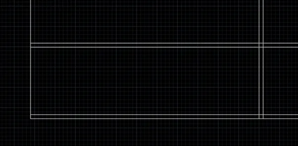
STEP 2:
- Enter MI in command box
- Select the object and create mirrored objects
- Enter YES in command to erase the source
- Enter O in command box.
- Enter 1163 as offset distance
- Enter O in command box.
- Enter 12 as offset distance
- Enter O in command box.
- Enter 1230 as offset distance
- Enter O in command box.
- Enter 12 as offset distance
- Enter O in command box.
- Enter 365 as offset distance
- Enter O in command box.
- Enter 12 as offset distance
- Enter O in command box.
- Enter 545 as offset distance
- Enter O in command box.
- Enter 5 as offset distance
- Enter O in command box.
- Enter 629 as offset distance
- Enter O in command box.
- Enter 5 as offset distance
- Enter O in command box.
- Enter 621 as offset distance
- Enter O in command box.
- Enter 5 as offset distance
- Enter O in command box.
- Enter 618 as offset distance
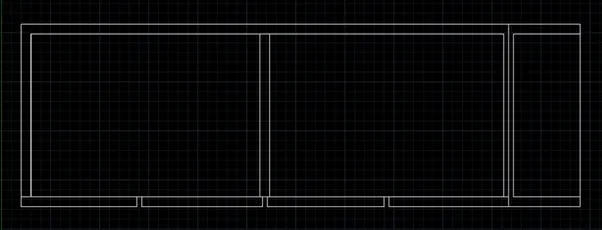
STEP 3:
- Enter L in command box
- Click the start point and enter 391 by switching off ORTHOMODE.
- Enter C in command box
- Click the 391 point and connect it to 5 mm offset
- Enter MI in command box
- Select the door and mirror it
- Enter NO to erase the source
- Enter M in command box
- Move the mirrored object which sets between 629 mm offset
- Enter CO in command box
- Select the first door and copy it to 621 mm offset
- Enter CO in command box
- Select the second door and copy it to 618 mm offset
- Enter CO in command box
- Select the first door and copy it
- Enter RO in command box
- Rotate it to 90
- Move it to right side
- Enter REC in command box
- Click DIMENSIONS
- Enter 30 as length
- Enter 45 as width
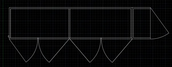
STEP 4:
- Enter L in command box
- Enter 100 in command box
- Enter 800 in command box
- Enter 2800 in command box
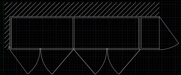
- Enter C in command box
- Enter 147 as radius
- Enter L in command box
- Switch off ORTHOMODE
- Create 2 arrows
- Enter TR in command box
- Delete the line between arrows
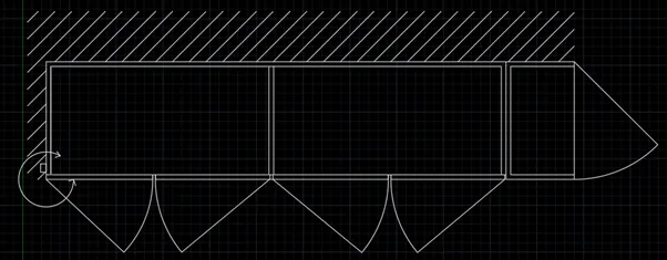
STEP 5:
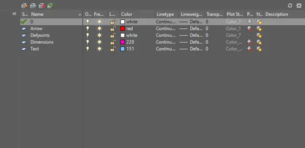
- Click LAYER PROPERTIES
- Click NEW LAYER option
- Enter ARROW, DIMENSIONS and TEXT in NEW LAYER
- Select RED for ARROW, 220 for DIMENSIONS and 151 for TEXT in COLOUR
STEP 6:
- Enter DIMS in command box
- Click MODIFY. In SYMBOLS and ARROWS, Enter ARROW SIZE as 70.
- In TEXT, Enter TEXT HEIGHT as 70.
- In PRIMARY UNITS, Click DECIMAL in UNIT FORMAT, 0 in PRECISION.
- In LINES, Enter 10 as EXTEND BEYOND LINES and 20 as OFFSET FROM ORIGIN. Click OK.
- Click SET CURRENT. Click CLOSE.
- Click DIMENSIONS AND TEXT dropdown in LAYER.
- Enter DIML in command box and drag the dimensions.
- Enter DT in command box. Enter 70 as TEXT HEIGHT and 0 as TEXT ROTATION ANGE.
- Enter TEXT.
- Enter CO in command box. Copy the text and place it in another location.
- Enter TEXTEDIT in command box. Using this, editing in text can be done.
- Click the layers to give their properties in diagrams
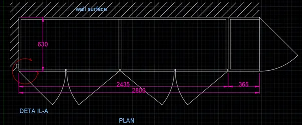
(b)FRONT ELEVATION
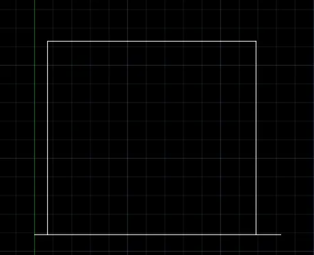
STEP 1:
- Enter L in command box
- Click the line at the height of 400 from plan
- Enter @2800,0 in command box
- Enter @0,2600 in command box
- Enter @-2800,0 in command box
- Enter @0, -2600 in command box
- Enter EXTEND in command box
- Select the lower line to extend beyond.
STEP 2:
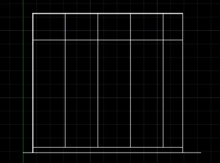
- Enter O in command box
- Enter 12 as offset distance
- Create offset on left side and upper side
- Enter O in command box
- Enter 100 as offset distance
- Enter O in command box
- Enter 488 as offset distance
- Enter O in command box
- Enter 597 as offset distance
- Create offset for 3 more times
STEP 3:
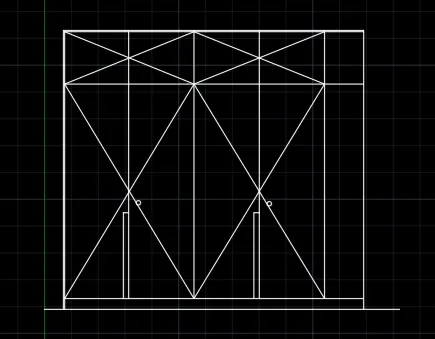
- Enter L in command box
- Click at 597 bottom line
- Enter 800 in command box
- Enter 50 in command box
- Enter CO in command box
- Copy the rectangle at other side
- Switch off ORTHOMODE
- Create diagonal lines at both side
- Enter C in command box
- Enter 20 as radius
- Enter M in command box
- Move the circle on the diagonal line
- Enter CO in command box
- Place it on other diagonal line
STEP 4:
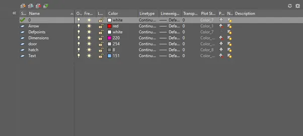
- Click LAYER PROPERTIES
- Click NEW LAYER option
- Enter DOOR and HATCH in NEW LAYER
- Select 254 for DOOR and 8 for HATCH in COLOUR
STEP 5:
- Enter H in command box
- Select ANSI34 pattern
- Click it on the object to be hatched
- Increase the scale to 20
- Enter DIML in command box and drag the dimensions.
- Enter TEXT.
- Enter CO in command box. Copy the text and place it in another location.
- Enter TEXTEDIT in command box. Using this, editing in text can be done.
- Click the layers to give their properties in diagrams
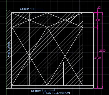
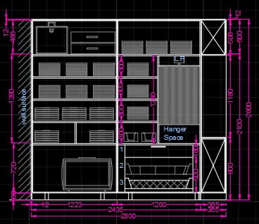
(c)CARCASE ELEVATION
STEP 1:
- Enter L in command box
- Click the line at the height of 400 from plan
- Enter @2800,0 in command box
- Enter @0,2600 in command box
- Enter @-2800,0 in command box
- Enter @0, -2600 in command box
- Enter EXTEND in command box
- Select the lower line to extend beyond.
- Enter O in command box
- Enter 12 as offset distance
- Create offset for left and upper sides
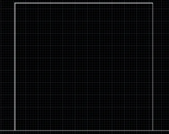
STEP 2:
- Enter O in command box
- Enter 1223 as offset distance
- Enter O in command box
- Enter 1200 as offset distance
- Enter O in command box
- Enter 365 as offset distance
- Enter O in command box
- Enter 12 as offset distance
- Create offset for 1223 and 1200 lines
- Enter O in command box
- Enter 100 as offset distance
- Enter O in command box
- Enter 720 as offset distance
- Enter O in command box
- Enter 1260 as offset distance
- Enter O in command box
- Enter 20 as offset distance
- Create 4 offsets for 1260
- Enter O in command box
- Enter 188 as offset distance
- Enter O in command box
- Enter 800 as offset distance
- Enter O in command box
- Enter 400 as offset distance
- Enter O in command box
- Enter 955 as offset distance
- Enter O in command box
- Enter 68 as offset distance
- Enter O in command box
- Enter 50 as offset distance
- Create three 50 offset
- Enter O in command box
- Enter 12 as offset distance
- Enter TR in command box
- Delete the unwanted lines
- Switch off ORTHOMODE
- Create diagonal lines
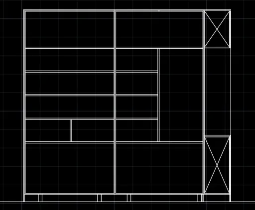
STEP 3:
- Enter O in command box
- Enter 50 as offset distance
- Enter O in command box
- Enter 150as offset distance
- Enter O in command box
- Enter 57 as offset distance
- Switch off ORTHOMDE
- Enter L in command box
- Enter 50 in command box
- Enter 100 and connect it to 50
- Enter MI in command box
- Create mirrored object
- Enter M and move it to opposite side
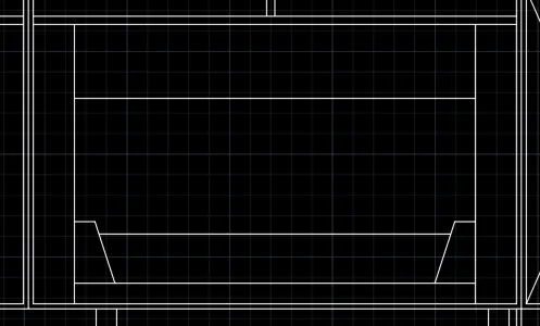
- Enter L in command box
- Enter 120 in command box
- Enter CO and copy it at 57 distance
- Enter L in command box
- Enter 120 in command box
- Enter 220 in command box
- Enter 280 in command box
- Enter L in command box
- Enter 12 in command box
- Enter 200 in command box
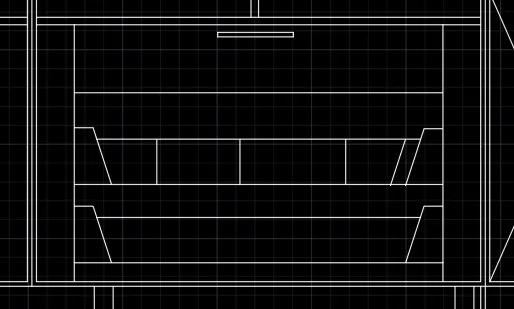
STEP 4:
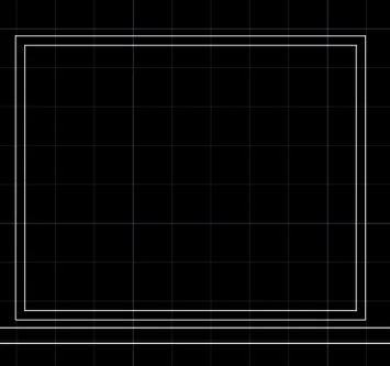
- Enter L in command box
- Enter 50 in command box
- Enter @450,0 in command box
- Enter @0,395 in command box
- Enter @-450,0 in command box
- Enter @0, -395 in command box
- Enter O in command box
- Enter 12 as offset distance
- Create offset at 4 sides
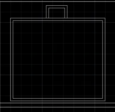
- Enter L in command box
- Enter 170 in command box
- Enter 100 in command box
- Enter 60 in command box
- Enter 100 in command box
- Enter 60 in command box
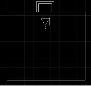
- Enter L in command box
- Enter 50 in command box
- Enter 40 in command box
- Enter 12 in command box
- Enter 5 in command box
- Switch off ORTHOMODE
- Create diagonal lines
STEP 5:
- Enter REC in command box
- Enter 230 as length in command box
- Enter 150 as width in command box
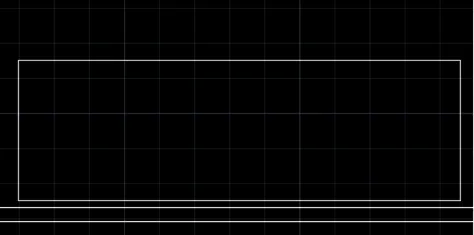
- Enter REC in command box
- Enter 230 as first corner point
- Enter 150 as length in command box
- Enter 20 as width in command box
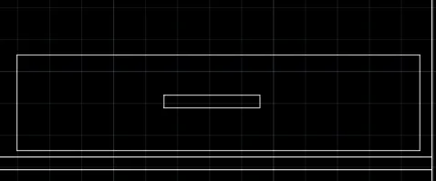
- Enter CO in command box
- Select the object and enter 15
- Place the rectangle at 15 distance
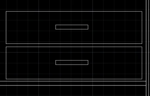
STEP 6:
- Enter REC in command box
- Enter 57 as first corner point
- Enter 300 as length
- Enter 15 as width
- Enter M and move it at 10 distance
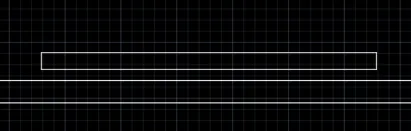
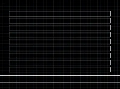
- Enter CO in command box
- Select the object
- Click ARRAY and enter 8
- Click FIT and enter 6
- Enter CO in command box
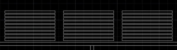
- Select the object
- Click ARRAY and enter 2
- Click FIT and enter 50
- Enter CO in command box
- Select the object
- Click ARRAY and enter 2
- Click FIT and enter 90
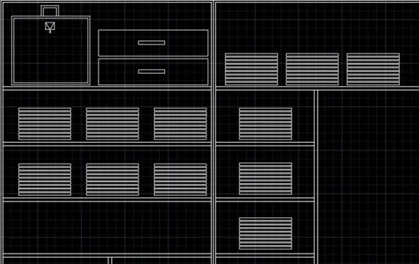
- Enter CO in command box
- Select the object
- Click ARRAY and enter 2
STEP 7:
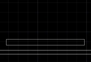
- Enter REC in command box
- Enter 320 as length in command box
- Enter 24 as width in command box
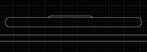
- Enter ARC in command box
- Create arcs on both sides
- Enter REC in command box
- Enter 112 as length in command box
- Enter 100 as width in command box
- Switch off ORTHOMODE
- Connect it to 100 distance
- Delete the unwanted lines
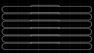
- Enter CO in command box
- Select the object
- Click ARRAY and enter 5
- Click FIT and enter 5
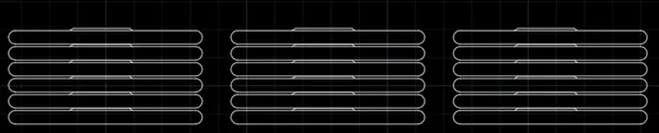
- Enter CO in command box
- Select the object
- Click ARRAY and enter 2
- Click FIT and enter 75
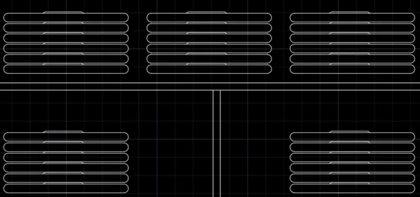
- Enter CO in command box
- Select the object
- Copy it at 164 distance
STEP 8:
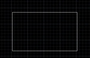
- Enter REC in command box
- Enter 200 as length in command box
- Enter 120 as width in command box
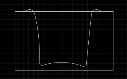
- Enter ARC in command box
- Create arcs
- Enter TR in command box
- Delete the unwanted lines
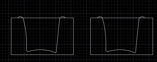
- Enter CO in command box
- Copy the object at 55 distance
STEP 9:
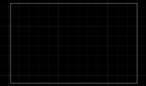
- Enter REC in command box
- Enter 440 as first corner point
- Enter 680 as length in command box
- Enter 445 as width in command box
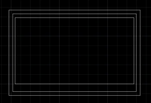
- Enter O in command box
- Enter 20 as offset distance
- Enter O in command box
- Enter 40 as offset distance
- Enter O in command box
- Enter 20 as offset distance
- Enter O in command box
- Enter 12 as offset distance
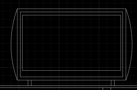
- Enter ARC in command box
- Create arcs on both sides
- Enter L in command box
- Enter 68 in command box
- Enter 520 in command box
- Enter O in command box
- Enter 20 as offset distance
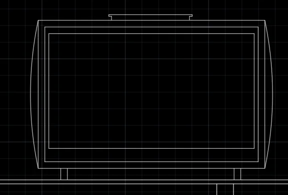
- Enter L in command box
- Enter 220 as first point
- Enter 12 as next point
- Enter 8 as next point
- Enter 5 as next point
- Enter 250 as next point
- Enter 5 as next point
- Enter 8 as next point
- Enter 12 as next point
STEP 10:
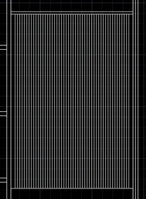
- Enter L in command box
- Enter 138 as first point
- Enter 588 as next point
- Enter O in command box
- Enter 12 as offset distance
- Enter O in command box
- Enter 840 as offset distance
- Enter L in command box
- Enter 12 and 840
- Enter CO in command box
- Select the object
- Click ARRAY and enter 50
- Click FIT and enter 10
STEP 11:
- Enter DIML in command box
- Click the points to get dimensions
- Enter DT in command box
- Enter 70 as text height
- Enter the text
- Use TEXTEDIT AND CO for editing and copying the text
- Click the layers and place it on the dimensions, objects and text
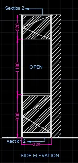
(d)SIDE ELEVATION
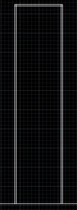
STEP 1:
- Enter L in command box
- Enter @530,0 as first point
- Enter @630,0 as next point
- Enter @0,2600 as next point
- Enter @-630,0 as next point
- Enter @0, -2600 as next point
- Enter O in command box
- Enter 12 as offset distance
- Create offset on 3 sides
STEP 2:
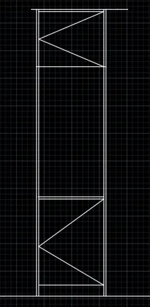
- Enter O in command box
- Enter 100 as offset distance
- Enter O in command box
- Enter 800 as offset distance
- Enter O in command box
- Enter 1180 as offset distance
- Enter O in command box
- Enter 20 as offset distance
- Switch off ORTHOMODE
- Create diagonal lines
STEP 3:
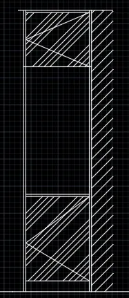
- Enter H in command box
- Create ANSI31 hatch pattern
- Increase scale to 20
- Create ANSI34 hatch pattern
- Pick points and click the hatch
- Increase scale to 20
STEP 4:
- Enter DIML in command box
- Click the points to get dimensions
- Enter DT in command box
- Enter 70 as text height
- Enter the text
- Use TEXTEDIT AND CO for editing and copying the text
- Click the layers and place it on the dimensions, objects and text
(e)SECTION-1
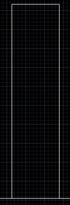
STEP 1:
- Enter L in command box
- Enter @530,0 as first point
- Enter @630,0 as next point
- Enter @0,2600 as next point
- Enter @-630,0 as next point
- Enter @0, -2600 as next point
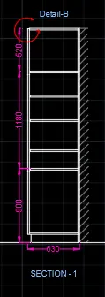
STEP 2:
- Enter O in command box
- Enter 12 as offset distance
- Enter O in command box
- Enter 100 as offset distance
- Enter O in command box
- Enter 800 as offset distance
- Enter O in command box
- Enter 225 as offset distance
- Enter O in command box
- Enter 365 as offset distance
- Enter O in command box
- Enter 295 as offset distance
- Enter O in command box
- Enter 295 as offset distance
- Create ANSI34 hatch
- Enter CO in command box
- Copy the direction circle and place.
- Enter DIML in command box
- Click the points to get dimensions
- Enter DT in command box
- Enter 70 as text height
- Enter the text
- Use TEXTEDIT AND CO for editing and copying the text
- Click the layers and place it on the dimensions, objects and text
(f)SECTION-2
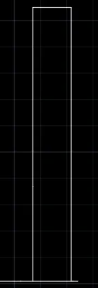
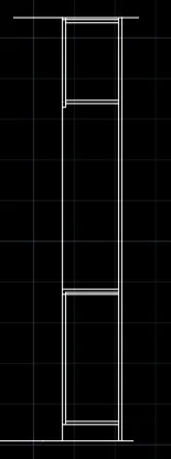
STEP 1:
- Enter L in command box
- Enter @365,0 as first point
- Enter @0,2600 as next point
- Enter @-365,0 as next point
- Enter @0, -2600 as next point
STEP 2:
- Enter O in command box
- Enter 100 as offset distance
- Enter O in command box
- Enter 800 as offset distance
- Enter O in command box
- Enter 1180 as offset distance
- Enter O in command box
- Enter 12 as offset distance
STEP 3:
- Enter CO in command box
- Copy the direction circle and place.
- Enter DIML in command box
- Click the points to get dimensions
- Enter DT in command box
- Enter 70 as text height
- Enter the text
- Use TEXTEDIT AND CO for editing and copying the text
- Click the layers and place it on the dimensions, objects and text
- Save the drawing and rename it as AUTOCAD CHALLENGE 6.
RESULT:
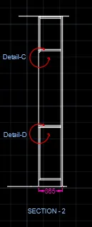
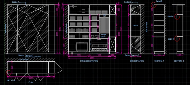
The elevation and details of a wardrobe is created by lines using AutoCAD. The step-by-step procedure for creating elevation and details of a wardrobe is also explained. The Dimension is also entered in the diagram.
2)FLOOR PLAN
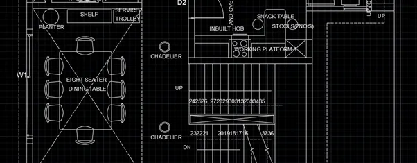
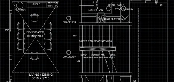
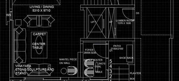
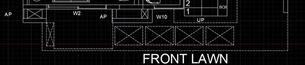
AIM: To create the floor plan using AutoCAD.
INTRODUCTION: The floor plan using AutoCAD is created by Lines and Circles. The procedure and result should be written after creating the floor plan.
PROCEDURE:
STEP 1:
- Open the AutoCAD software and click start Drawing tab.
- Enter UNITS in command box.
- Select DECIMAL in TYPE, 0 in PRECISION and MILLIMETERS in UNITS TO SCALE INSERTED CONTENT. Press OK.
- Switch on ORTHOMODE.
- Enter XL in command box
- Enter H and draw horizontal line
- Enter XL in command box
- Enter V and draw vertical line
- Enter L in command box
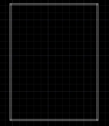
- Enter @14244,0 as first point
- Enter @0,21800 as next point
- Enter @-14244,0 as next point
- Enter @0, -21800 as next point
- Enter O in command box
- Enter 230 as offset distance
- Create offset at four sides
STEP 2:
- Enter L in command box
- Enter @1260,0 as first point
- Enter @0, -730 as next point
- Enter @-1260,0 as first point
- Enter @0,730 as next point
- Enter O in command box
- Enter 230 as offset distance
- Create offset at three sides
- Enter O in command box
- Enter 80 as offset distance
- Enter O in command box
- Enter 3150 as offset distance
- Enter O in command box
- Enter 700 as offset distance
- Enter O in command box
- Enter 1260 as offset distance
- Enter L in command box
- Enter @730,0 as first point
- Enter @0, -2165 as next point
- Enter @-730,0 as first point
- Enter @0,2165 as next point
- Enter O in command box
- Enter 230 as offset distance
- Create offset at three sides
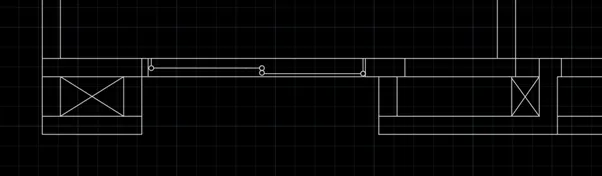
- Switch off ORTHOMODE
- Create diagonal lines
- Enter C in command box
- Enter 30 as radius
- Place it at appropriate place
- Enter CO and copy 3 more circles
- Connect those with lines
STEP 3:
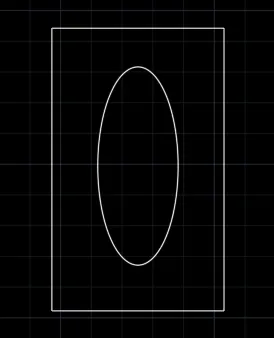
- Enter REC in command box
- Enter 1400 as length
- Enter 2300 as width
- Enter ELLIPSE in command box
- Create ellipse at the centre of the rectangle
STEP 4:
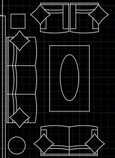
- Enter L in command box
- Enter @1000,0 as first point
- Enter @0, -3000 as next point
- Enter @-1000,0 as first point
- Enter @0,3000 as next point
- Enter ARC in command box
- Create arcs for 3 rectangles
- Copy the arcs and place it at 800 distance
- Enter O and create offset at 200
- Enter REC in command box
- Enter 500 as length
- Enter 500 as width
- Enter ARC and create arc at four sides of square
- Enter CO and copy the square at either sides
- Enter L in command box
- Enter @2000,0 as first point
- Enter @0, -1000 as next point
- Enter @-2000,0 as first point
- Enter @0,1000 as next point
- Enter ARC in command box
- Create arcs for 3 rectangles
- Copy the arcs and place it at 800 distance
- Enter O and create offset at 200
- Copy and place the squares
- Copy the sofa and rotate it to 180
- Enter L in command box
- Enter @200 as first point
- Enter @0,600 as next point
- Copy the square and place it
- Enter C in command box
- Enter 300 as radius
- Place it at corner
- Enter C in command box
- Enter 200 as radius
- Place it at right side
STEP 5:
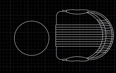
- Enter REC in command box
- Enter 600 as length
- Enter 400 as width
- Enter ARC in command box
- Create 3 arcs
- Enter REC in command box
- Enter 300 as length
- Enter 50 as width
- Create arc at both sides
- Copy the object and place it at both sides of sofa
- Create arcs at left side
- Create offsets at sofa
STEP 6:
- Enter REC in command box
- Enter 2000 as length
- Enter 3000 as width
- Enter L in command box
- Enter 500 as first point
- Switch off ORTHOMODE
- Enter 50 as next point
- Create diagonal lines
- Create arc in the rectangle of 700 length and 50 width
- Enter 20 as fillet
- Copy the chair and place at appropriate places
- Create diagonal lines
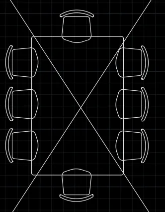
STEP 7:
- Enter L in command box
- Enter 900 as first point
- Enter 310 as next point
- Enter 900 as next point
- Enter C in command box
- Enter 180 as radius
- Enter C in command box
- Enter 170 as radius
- Enter L in command box
- Enter 30 as first point
- Enter O in command box
- Enter 10 as offset distance
- Enter L in command box
- Enter 350 as first point
- Enter 350 as next point
- Enter O and type 50 as offset distance
- Create arc
- Enter 50 as offset and join it
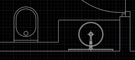
STEP 8:
- Enter L in command box
- Enter 988 as first point
- Enter 1000 as next point
- Enter C in command box
- Create circle and place it
- Enter TR in command box
- Delete the unwanted lines
- Enter L in command box
- Switch off ORTHOMODE
- Create offset of 5
- Copy the object and place it
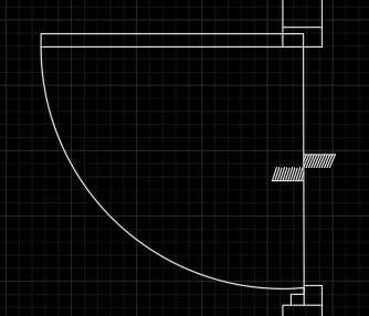
STEP 9:
- Enter L in command box
- Enter 500 as first point
- Enter 900 as next point
- Enter 230 as next point
- Enter 800 as offset distance
- Copy the square and place it
- Connect it with other squares through line
- Switch off ORTHOMODE
- Create diagonal lines
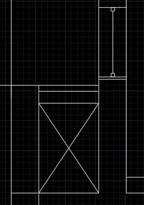
STEP 10:
- Enter L in command box
- Enter 1000 as first point
- Enter 5000 as next point
- Enter 2000 as next point
- Enter 1000 as next point
- Enter 2000 as next point
- Connect it to 1000 distance line
- Enter ARC in command box
- Create ARC and copy it
- Enter 200 as offset
- Copy the squares and place
- Create ELLIPSE and place
- Copy the square and place it
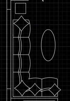
STEP 11:
- Enter L in command box
- Copy the squares and place
- Connect it with squares
- Enter L in command box
- Enter 1900 as first point
- Enter 800 as next point
- Enter 1900 as next point
- Enter O in command box
- Enter 300 as offset distance
- Create 3 offsets
- Enter L in command box
- Enter 50 as first point
- Enter O in command box
- Enter 10 as offset distance
- Copy it and place it another side
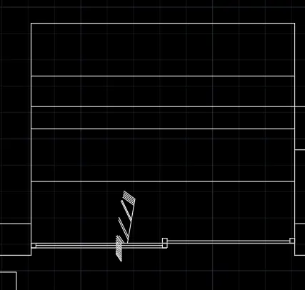
STEP 12:
- Enter L in command box
- Enter 200 as first point
- Enter 300 as next point
- Enter 200 as next point
- Enter 230 as offset distance
- Create it 3 sides
- Create diagonal lines
- Enter L in command box
- Enter 200 as first point
- Enter 250 as next point
- Enter 200 as next point
- Enter 230 as offset distance
- Create it 3 sides
- Create diagonal lines
- Create offset of 100 and 500
- Copy the squares
- Connect it with lines
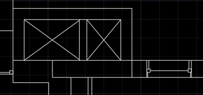
STEP 13:
- Enter L in command box
- Enter 200 as first point
- Enter 350 as next point
- Enter 200 as next point
- Enter 150 as offset distance
- Create it 3 sides
- Copy the squares
- Place it at 4 locations
- Connect with lines
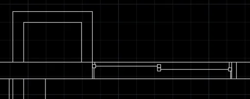
Step 14:
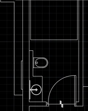
- Copy the toilet, clock and door
- Place it at appropriate distance
- Enter L in command box
- Enter 1000 as first point
- Enter 2000 as next point
- Enter 1000 as next point
- Enter 2000 as next point
STEP 15:
- Enter L in command box
- Enter 500 as first point
- Enter 800 as next point
- Enter 500 as next point
- Enter 800 as next point
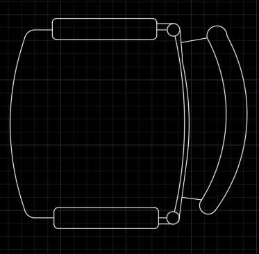
- Enter ARC in command box
- Create arcs and connect
- Enter 50 as fillet
- Enter REC in command box
- Enter 150 as length
- Enter 20 as width
- Copy it and place it on another side
- Enter 20 as fillet radius
- Enter C with radius 50 in command box
- Copy the circle
- Connect it with lines
STEP 16:
- Enter L in command box
- Enter 1800 as first point
- Enter 2500 as next point
- Enter 1800 as next point
- Enter 2500 as next point
- Enter 300 as offset distance
- Enter 50 as offset distance
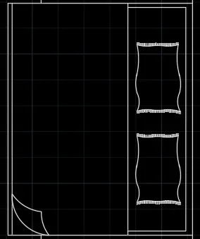
- Enter ARC in command box
- Create arc and connect it with line
- Enter REC in command box
- Enter 100 as length
- Enter 150 as width
- Create arc at four sides
- Create offset of 10 distance
- Copy the object
- Place it at 100
STEP 17:
- Enter L in command box
- Enter 1000 as first point
- Enter 3500 as next point
- Enter 1000 as next point
- Enter 3500 as next point
- Create 100 distance as offset
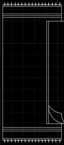
- Create arc and place
- Copy the arc and place at 50
STEP 18:
- Enter L in command box
- Enter 3500 as first point
- Enter 800 as next point
- Enter 3500 as next point
- Enter 50 as offset
- Enter 1000 as offset
- Enter 50 as offset
- Create offset and place it
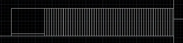
STEP 19:
- Enter REC
- Enter 500 as length
- Enter 500 as width
- Enter REC
- Enter 500 as length
- Enter 1500 as width
- Place at appropriate place
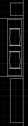
STEP 20:
- Enter O in command box
- Enter 50 as offset distance
- Place at 300 offset
- Copy square and place it connecting with line
- Enter 50 as offset distance at 3
STEP 21:
- Enter L in command box
- Enter 150 as offset distance
- Place at 3 sides
- Create diagonal lines
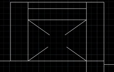
STEP 22:
- Enter L in command box
- Enter 500 as first point
- Enter 100 as next point
- Enter 500 as next point
- Enter 300 as next point
- Enter 300 as offset distance
- Enter 600 as next point
- Create 100 as offset
- Connect with arcs
- Create circle with radius of 50
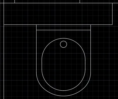
STEP 23:
- Enter L in command box
- Enter 100 as first point
- Enter 300 as next point
- Enter 100 as first point
- Enter 50 as first point
- Switch off ORTHOMODE
- Create inclined lines
- Create 100 as fillet radius
- Create 100 as offset distance
- Create circle with radius 50 and 30
- Copy and place connecting with lines
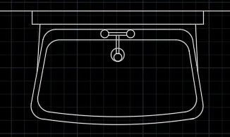
STEP 24:
- Copy the door
- Place the objects in the appropriate place

STEP 25:
- Copy the door and place
- Enter L and type 200
- Type 50 as next point
- Copy the circles
- Place it with lines
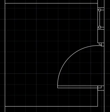
STEP 26:
- Enter L in command box
- Enter 500 as first point
- Enter 2000 as next point
- Enter 500 as next point
- Enter 2000 as next point
- Create diagonal lines
- Enter 300 as length
- Enter 400 as width
- Create wash basin
- Enter 50 as fillet radius
- Enter 100 as length
- Enter 20 as width
- Copy and place
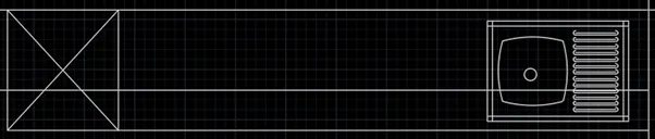
STEP 27:
- Enter L in command box
- Enter 600 as first point
- Enter 400 as next point
- Enter 600 as next point
- Enter 400 as next point
- Enter 200 as next point
- Enter 400 as next point
- Enter 200 as next point
- Enter 20 as fillet radius
- Enter L in command box
- Connect it at both sides
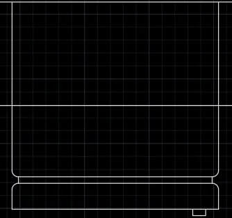
STEP 28:
- Enter L in command box
- Enter 300 as first point
- Enter 800 as next point
- Enter 300 as next point
- Enter 300 as next point
- Enter 500 as next point
- Enter 300 as next point
- Enter 800 as next point
- Enter C in command box
- Create circle with radius of 300 and 150
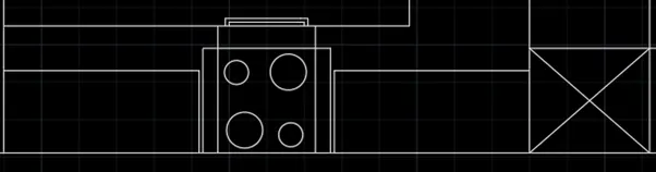
STEP 29:
- Copy the door
- Enter L in command box
- Enter 500 as first point
- Enter 1000 as next point
- Enter 900 as next point
- Enter 600 as next point
- Enter 900 as next point
- Enter 500 as next point
- Enter fillet radius as 50
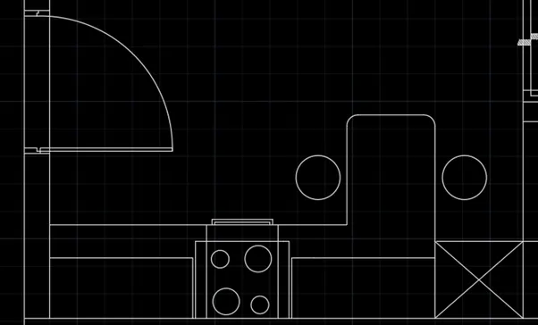
STEP 30:
- Enter L in command box
- Enter 1000 as first point
- Enter 500 as next point
- Enter 150 as offset
- Create offset and place it at appropriate place
- Enter 100 as next point
- Create offset at 100
- Connect it at 50
- Create diagonal lines
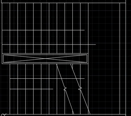
STEP 31:
- Enter L in command box
- Enter 500 as first point
- Enter 800 as next point
- Create diagonal lines
- Enter 200 as next point
- Enter 800 as next point
- Create diagonal lines
- Copy the door and place
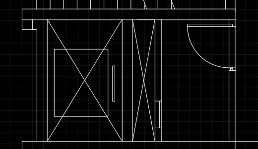
STEP 32:
- Copy the sofa and place at 2 places
- Create ELLIPSE and place it
- Copy the door and place
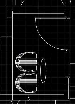
STEP 33:
- Enter REC in command box
- Enter 100 as length
- Enter 250 as width
- Enter 200 as offset distance
- Place 3 offsets
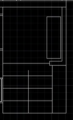
STEP 34:
- Copy the door
- Enter L in command box
- Enter 400 as first point
- Enter 500 as next point
- Enter REC in command box
- Enter 200 as next point
- Enter 500 as next point
- Enter 250 as next point
- Enter 500 as next point
- Enter 250 as next point
- Create offset distance at 50
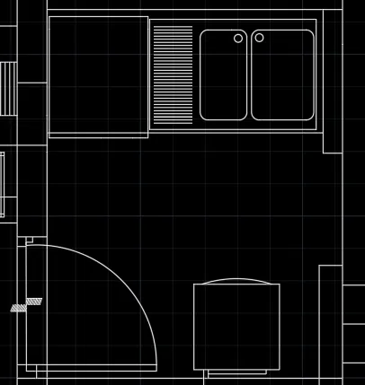
STEP 35:
- Create radius as 500 as circle
- Create radius as 150 as circle
- Enter L in command box
- Enter 100 as first point
- Enter 75 as next point
- Enter ARC in command box
- Create arcs in rectangle
- Copy the arc and offset of 50
- Enter 50 as first point
- Enter 100 as next point
- Enter 50 as next point
- Enter 100 as next point
- Copy the object and place at appropriate places
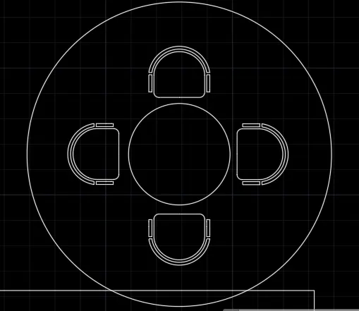
STEP 36:
- Click LAYER PROPERTIES
- Click NEW LAYER
- Enter LAYER in NAME and ACADS in LINETYPE
- Place the layer with objects
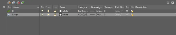
STEP 37:
- Enter DIMS in command box
- Click MODIFY. In SYMBOLS and ARROWS, Enter ARROW SIZE as 70.
- In TEXT, Enter TEXT HEIGHT as 70.
- In PRIMARY UNITS, Click DECIMAL in UNIT FORMAT, 0 in PRECISION.
- In LINES, Enter 10 as EXTEND BEYOND LINES and 20 as OFFSET FROM ORIGIN. Click OK.
- Click SET CURRENT. Click CLOSE.
- Click DIMENSIONS AND TEXT dropdown in LAYER.
- Enter DIML in command box and drag the dimensions.
- Enter DT in command box. Enter 70 as TEXT HEIGHT and 0 as TEXT ROTATION ANGE.
- Enter TEXT.
- Enter CO in command box. Copy the text and place it in another location.
- Enter TEXTEDIT in command box. Using this, editing in text can be done.
- Click the layers to give their properties in diagrams
RESULT:
The Floor plan is created by lines using AutoCAD. The step-by-step procedure for creating floor plan is also explained. The Dimension is also entered in the diagram.
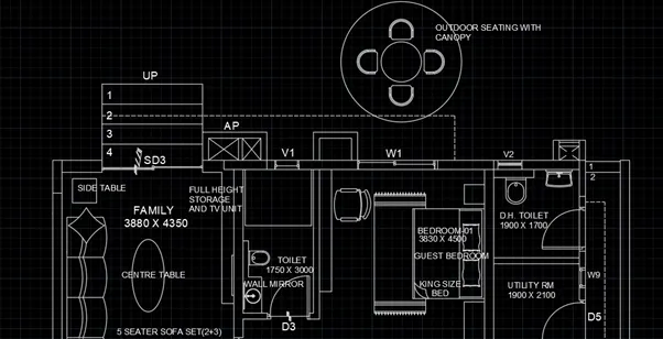
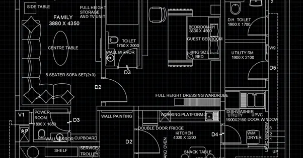
3)KITCHEN LAYOUT
AIM: To create the kitchen layout using AutoCAD.
INTRODUCTION: The kitchen layout using AutoCAD is created by Lines and Circles. The procedure and result should be written after creating the kitchen layout.
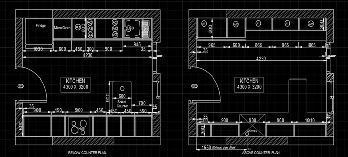
(a)BELOW COUNTER PLAN
PROCEDURE:
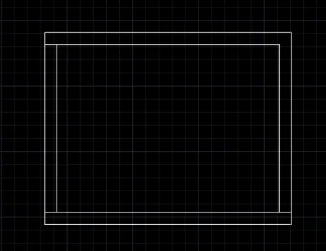
STEP 1:
- Open the AutoCAD software and click start Drawing tab.
- Enter UNITS in command box.
- Select DECIMAL in TYPE, 0 in PRECISION and MILLIMETERS in UNITS TO SCALE INSERTED CONTENT. Press OK.
- Switch on ORTHOMODE.
- Enter L and type 0,0 in command box.
- Type @4690,0 in command box.
- Type @ 0,3660 in command box.
- Type @-4690 in command box.
- Type @0, -3660 in command box.
- Enter O in command box
- Enter 230 as offset distance
- Place it at four sides
- Enter TR in command box
- Delete the unwanted lines
STEP 2:
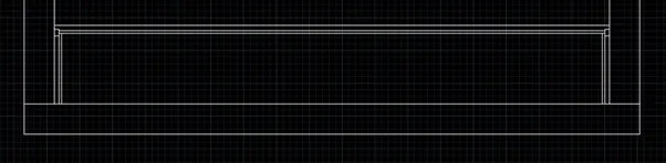
- Enter L in command box
- Enter 35 as first point
- Enter 50 as next point
- Enter 35 as next point
- Enter O in command box
- Enter 600 as offset distance
- Enter 4230 as next point
- Click it at midpoint of 35
- Connect it at other end
- Click the midpoint and connect it at bottom
- Create an offset of 20
- Create offset at 3 sides
STEP 3:
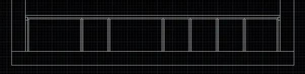
- Create offset as 900, 450, 900, 450, 450, 450 and 560
- Create offset at 20
- Select the line and create offsets
STEP 4:
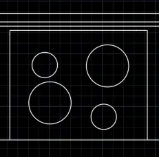
- Enter L in command box
- Enter 100 as first point
- Enter 550 as next point
- Enter 700 as next point
- Enter 550 as first point
- Enter C in command box
- Enter 200 as radius
- Enter 150 as radius
- Copy the circle and place
STEP 5:
- Enter L in command box
- Enter 35 as first point
- Enter 50 as next point
- Enter 35 as next point
- Enter O in command box
- Enter 600 as offset distance
- Enter 20 as offset distance
- Enter 900, 945,300,450 and 600 as offset distance
- Enter 20 as offset distance
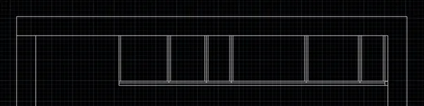
STEP 6:
- Enter L in command box
- Enter 50 as first point
- Enter 900 as next point
- Enter 700 as next point
- Enter 100 as next point
- Enter 900 as next point
- Enter 100 as next point
- Enter 20 as fillet radius
- Enter L in command box
- Connect it to both sides
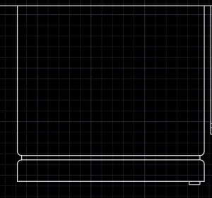
STEP 7:
- Enter 645 as offset distance
- Enter 20 as offset distance
- Enter 100 as first point
- Enter 20 as next point
- Copy the object and place
- Enter 50 as first point
- Enter 100 as next point
- Enter 100 as next point
- Enter 50 as next point
- Mirror the lines
- Enter C in command box
- Enter 50 as radius
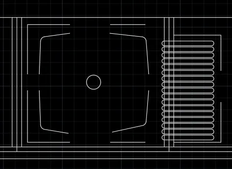
STEP 8:
- Enter L in command box
- Enter 100 as first point
- Enter 75 as next point
- Enter 50 as next point
- Enter 50 as next point
- Enter 25 as next point
- Enter MI in command box
- Copy the mirrored objects
- Place it at other side
- Enter C in command box
- Place the circle at the appropriate place
- Enter TR in command box
- Delete the unwanted lines
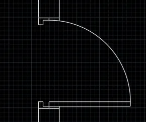
STEP 9:
- Enter L in command box
- Enter 100 as first point
- Enter 115 as next point
- Enter 50 as next point
- Enter 115 as next point
- Enter REC in command box
- Enter 30 as length
- Enter 30 as width
- Copy the squares connecting with lines
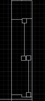
STEP 10:
- Enter L in command box
- Enter 75 as first point
- Enter 100 as next point
- Enter 50 as next point
- Enter 25 as next point
- Enter MI in command box
- Move the mirrored objects at opposite side
- Enter 200 as first point at mid point
- Switch off ORTHOMODE
- Enter 10 as offset distance
- Copy the object and place it
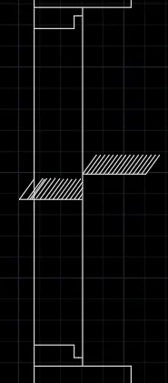
STEP 11:
- Enter L in command box
- Enter 50 as first point
- Enter 3735 as next point
- Enter 900 as next point
- Enter 600 as next point
- Enter 900 as next point
- Connect it with the end point
- Enter C in command box
- Enter 30 as radius
- Enter H in command box
- Click ANSI32 as hatch pattern with scale 20
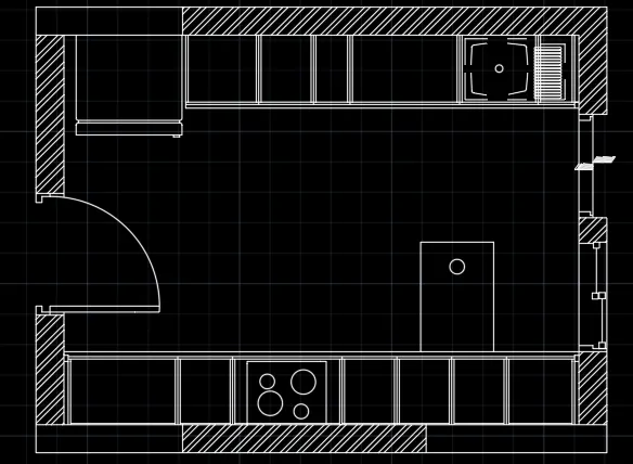
STEP 12:
- Click LAYER PROPERTIES
- Click NEW LAYER
- Enter SNACK COUNTER and LAYER in NAME
- Enter ACAD_ISO02W100 for LAYER and ACAD_ISO08W100 for SNACK COUNTER
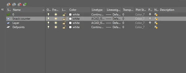
STEP 13:
- Enter DIMS in command box
- Click MODIFY. In SYMBOLS and ARROWS, Enter ARROW SIZE as 70.
- In TEXT, Enter TEXT HEIGHT as 70.
- In PRIMARY UNITS, Click DECIMAL in UNIT FORMAT, 0 in PRECISION.
- In LINES, Enter 10 as EXTEND BEYOND LINES and 20 as OFFSET FROM ORIGIN. Click OK.
- Click SET CURRENT. Click CLOSE.
- Click DIMENSIONS AND TEXT dropdown in LAYER.
- Enter DIML in command box and drag the dimensions.
- Enter DT in command box. Enter 70 as TEXT HEIGHT and 0 as TEXT ROTATION ANGE.
- Enter TEXT.
- Enter CO in command box. Copy the text and place it in another location.
- Enter TEXTEDIT in command box. Using this, editing in text can be done.
- Click the layers to give their properties in diagrams
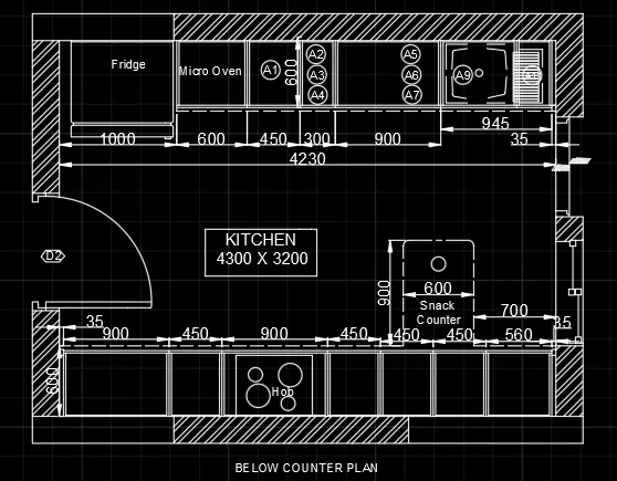
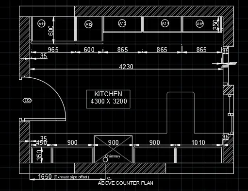
(b)ABOVE COUNTER PLAN
STEP 1:
- Copy the outer layer of the kitchen
- Enter L in command box
- Enter 35 as first point
- Enter 450 as offset distance
- Enter 900 as offset distance
- Enter 1010 as offset distance
- Enter 35 as offset distance
- Enter 20 as offset distance
- Create offset distance of 20

STEP 2:
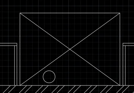
- Enter L in command box
- Enter 100 as first point
- Enter 600 as next point
- Enter 830 as next point
- Enter 600 as next point
- Switch off ORTHOMODE
- Create diagonal lines
- Enter C in command box
- Enter 200 as radius
STEP 3:
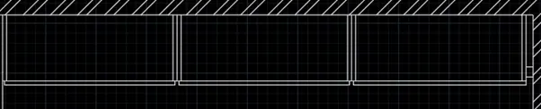
- Enter L in command box
- Enter 35 as first point
- Enter 350 as next point
- Enter 865 as offset distance
- Enter 20 as offset distance
- Create offsets of 20 at both sides
STEP 4:
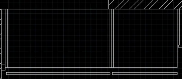
- Enter L in command box
- Enter 50 as first point
- Enter 600 as offset distance
- Enter 965 as offset distance
- Enter 35 as first point
- Enter 50 as next point
- Enter 35 as next point
- Enter 600 as offset distance
- Enter 20 as offset distance
- Create offsets and select the objects
STEP 5:
- Enter DIMS in command box
- Click MODIFY. In SYMBOLS and ARROWS, Enter ARROW SIZE as 70.
- In TEXT, Enter TEXT HEIGHT as 70.
- In PRIMARY UNITS, Click DECIMAL in UNIT FORMAT, 0 in PRECISION.
- In LINES, Enter 10 as EXTEND BEYOND LINES and 20 as OFFSET FROM ORIGIN. Click OK.
- Click SET CURRENT. Click CLOSE.
- Click DIMENSIONS AND TEXT dropdown in LAYER.
- Enter DIML in command box and drag the dimensions.
- Enter DT in command box. Enter 70 as TEXT HEIGHT and 0 as TEXT ROTATION ANGE.
- Enter TEXT.
- Enter CO in command box. Copy the text and place it in another location.
- Enter TEXTEDIT in command box. Using this, editing in text can be done.
- Click the layers to give their properties in diagrams
RESULT:
The Kitchen layout is created by lines using AutoCAD. The step-by-step procedure for creating kitchen layout is also explained. The Dimension is also entered in the diagram.
4)COLUMN DETAILS
AIM: To create the column details using AutoCAD.
INTRODUCTION: The column details using AutoCAD is created by Lines and Circles. The procedure and result should be written after creating the column details.
PROCEDURE:
(a)P1
STEP 1:
- Open the AutoCAD software and click start Drawing tab.
- Enter UNITS in command box.
- Select ENGINEERING in TYPE, 0’0” in PRECISION and INCHES in UNITS TO SCALE INSERTED CONTENT. Press OK.
- Switch on ORTHOMODE.
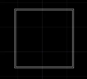
- Enter REC in command box
- Enter 24” as length
- Enter 24” as width
- Enter 0.5” as offset distance
- Select the rectangle and create offset
STEP 2:
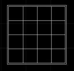
- Enter L in command box
- Enter 5.5 as first point
- Connect it to the end point
- Enter O in command box
- Enter 5.5 as offset distance
- Select the line and create 2 offsets
- Enter L in command box
- Enter 5.5 as first point
- Connect it to the end point
- Enter O in command box
- Enter 5.5 as offset distance
- Select the line and create 2 offsets
STEP 3:
- Enter C in command box
- Enter 0.62” as radius
- Enter CO in command box
- Copy the circle and place at appropriate position
- Enter 1” as fillet radius
- Select the circle and line to create curve shape
- Switch off ORTHOMODE
- Click on the circle and create lines
- Enter DO in command box
- Enter 0 as inner diameter
- Enter 1.24” as outer diameter
- Select MULTILINE TEXT in RIBBON.
- Click SYMBOL and select others.
- Click ARIAL as font and select Latin Small Letter Alpha (U+0251).
- Select it and press ENTER.
- Enter CO in command box and copy it in the required place.
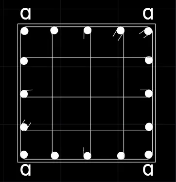
STEP 4:
- Enter REC in command box
- Enter 4’6” as length
- Enter 4’6” as width
- Enter L in command box
- Enter 6” as first point
- Enter L in command box
- Enter 6” as first point
- Enter 1’6” as next point
- Enter 1’ as next point
- Enter O in command box
- Enter 1’3” as offset distance
- Enter O in command box
- Enter 1’6” as offset distance
- Enter DIMS in command box
- Click MODIFY. In SYMBOLS and ARROWS, Enter ARROW SIZE as 1’.
- In TEXT, Enter TEXT HEIGHT as 1’.
- In PRIMARY UNITS, Click ENGINEERING in UNIT FORMAT, 0’0” in PRECISION.
- In LINES, Enter 1’ as EXTEND BEYOND LINES and 1’ as OFFSET FROM ORIGIN. Click OK.
- Click SET CURRENT. Click CLOSE.
- Enter DIML in command box
- Click the points to get dimensions
- Enter DT in command box
- Enter 1’ as text height
- Enter the text
- Use TEXTEDIT AND CO for editing and copying the text
- Click the layers and place it on the dimensions, objects and text
- Save the drawing and rename it as AUTOCAD CHALLENGE 6.
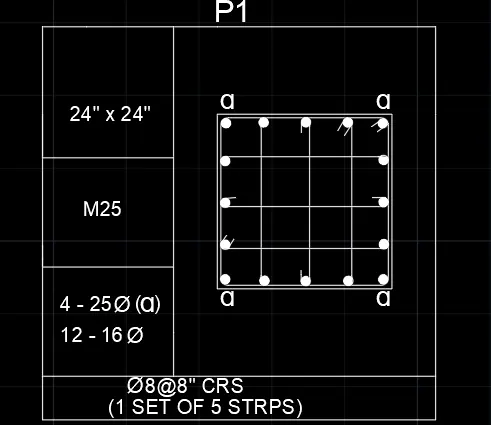
(b)P2
STEP 1:
- Open the AutoCAD software and click start Drawing tab.
- Enter UNITS in command box.
- Select ENGINEERING in TYPE, 0’0” in PRECISION and INCHES in UNITS TO SCALE INSERTED CONTENT. Press OK.
- Switch on ORTHOMODE.
- Enter REC in command box
- Enter 24” as length
- Enter 24” as width
- Enter 0.5” as offset distance
- Select the rectangle and create offset
- Enter L in command box
- Enter 5.5 as first point
- Connect it to the end point
- Enter O in command box
- Enter 5.5 as offset distance
- Select the line and create 2 offsets
- Enter L in command box
- Enter 5.5 as first point
- Connect it to the end point
- Enter O in command box
- Enter 5.5 as offset distance
- Select the line and create 2 offsets
- Enter C in command box
- Enter 0.62” as radius
- Enter CO in command box
- Copy the circle and place at appropriate position
- Enter 1” as fillet radius
- Select the circle and line to create curve shape
- Switch off ORTHOMODE
- Click on the circle and create lines
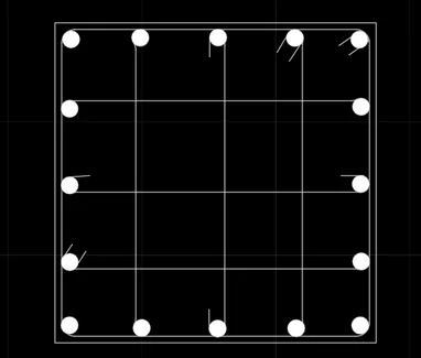
STEP 2:
- Enter REC in command box
- Enter 4’6” as length
- Enter 4’6” as width
- Enter L in command box
- Enter 6” as first point
- Enter L in command box
- Enter 6” as first point
- Enter 1’6” as next point
- Enter 1’ as next point
- Enter O in command box
- Enter 1’3” as offset distance
- Enter O in command box
- Enter 1’6” as offset distance
- Enter DIMS in command box
- Click MODIFY. In SYMBOLS and ARROWS, Enter ARROW SIZE as 1’.
- In TEXT, Enter TEXT HEIGHT as 1’.
- In PRIMARY UNITS, Click ENGINEERING in UNIT FORMAT, 0’0” in PRECISION.
- In LINES, Enter 1’ as EXTEND BEYOND LINES and 1’ as OFFSET FROM ORIGIN. Click OK.
- Click SET CURRENT. Click CLOSE.
- Enter DIML in command box
- Click the points to get dimensions
- Enter DT in command box
- Enter 1’ as text height
- Enter the text
- Use TEXTEDIT AND CO for editing and copying the text
- Click the layers and place it on the dimensions, objects and text
- Save the drawing and rename it as AUTOCAD CHALLENGE 6.
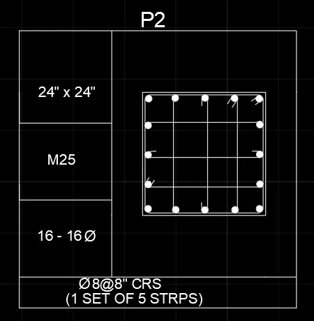
(c)P3
STEP 1:
- Open the AutoCAD software and click start Drawing tab.
- Enter UNITS in command box.
- Select ENGINEERING in TYPE, 0’0” in PRECISION and INCHES in UNITS TO SCALE INSERTED Press OK.
- Switch on ORTHOMODE.
- Enter REC in command box
- Enter 24” as length
- Enter 24” as width
- Enter 0.5” as offset distance
- Select the rectangle and create offset
- Enter L in command box
- Enter 5.5 as first point
- Connect it to the end point
- Enter O in command box
- Enter 5.5 as offset distance
- Select the line and create 2 offsets
- Enter L in command box
- Enter 5.5 as first point
- Connect it to the end point
- Enter O in command box
- Enter 5.5 as offset distance
- Select the line and create 2 offsets
- Enter C in command box
- Enter 0.62” as radius
- Enter CO in command box
- Copy the circle and place at appropriate position
- Enter 1” as fillet radius
- Select the circle and line to create curve shape
- Switch off ORTHOMODE
- Click on the circle and create lines
- Select MULTILINE TEXT in RIBBON.
- Click SYMBOL and select others.
- Click ARIAL as font and select Latin Small Letter Alpha (U+0251).
- Select it and press ENTER.
- Enter CO in command box and copy it in the required place.
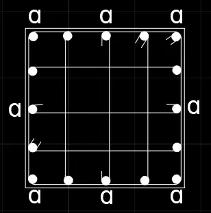
STEP 2:
- Enter REC in command box
- Enter 4’6” as length
- Enter 4’6” as width
- Enter L in command box
- Enter 6” as first point
- Enter L in command box
- Enter 6” as first point
- Enter 1’6” as next point
- Enter 1’ as next point
- Enter O in command box
- Enter 1’3” as offset distance
- Enter O in command box
- Enter 1’6” as offset distance
- Enter DIMS in command box
- Click MODIFY. In SYMBOLS and ARROWS, Enter ARROW SIZE as 1’.
- In TEXT, Enter TEXT HEIGHT as 1’.
- In PRIMARY UNITS, Click ENGINEERING in UNIT FORMAT, 0’0” in PRECISION.
- In LINES, Enter 1’ as EXTEND BEYOND LINES and 1’ as OFFSET FROM ORIGIN. Click OK.
- Click SET CURRENT. Click CLOSE.
- Enter DIML in command box
- Click the points to get dimensions
- Enter DT in command box
- Enter 1’ as text height
- Enter the text
- Use TEXTEDIT AND CO for editing and copying the text
- Click the layers and place it on the dimensions, objects and text
- Save the drawing and rename it as AUTOCAD CHALLENGE 6.
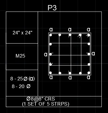
RESULT:
The Column details is created by lines using AutoCAD. The step-by-step procedure for creating column details is also explained. The Dimension is also entered in the diagram.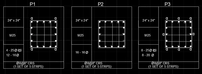
5)RAFT LAYOUT
AIM: To create the raft layout using AutoCAD.
INTRODUCTION: The raft layout using AutoCAD is created by Lines and Circles. The procedure and result should be written after creating the raft layout.
PROCEDURE:
STEP 1:
- Open the AutoCAD software and click start Drawing tab.
- Enter UNITS in command box.
- Select ENGINEERING in TYPE, 0’0” in PRECISION and INCHES in UNITS TO SCALE INSERTED CONTENT. Press OK.
- Switch on ORTHOMODE.
- Enter L in command box
- Enter 0,0 as first point
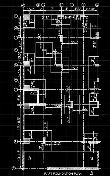
- Enter 10’-4 ½”, 13’-10 ½”, 5’9”, 3’9”, 5’-7 ½”, 5’-10 ½”, 4’9”, 3’-7 ½” and 5’-7 ½”
- Enter 5’9”, 2’, 7’, 4’, 4’6” and 5’-7 ½”
- Close the rectangle tracking the lines
STEP 2:
- Enter L in command box
- Enter 6’7.5” as first point
- Extend the line to other side
- Enter 9” as offset
- Enter 3’ as next point
- Enter 9” as next point
- Enter 24” as next point
- Enter 24” as next point
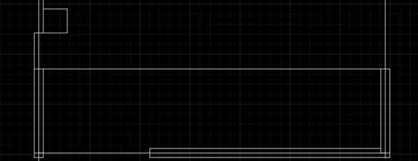
STEP 3:
- Enter O in command box
- Enter 10’-4 ½” as offset distance
- Extend the line
- Create the line tracking square
- Enter 9” as length
- Enter 28” as width
- Enter line at 2’6” after the rectangle
- Enter 2’6” above and close the line
- Create a rectangle
- Enter 18” as length
- Enter 9” as width
- Enter 3’ after rectangle
- Enter 6’9” above and close the line
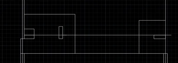
STEP 4:
- Enter O in command box
- Enter 13’-10 ½” as offset distance
- Enter L in command box
- Enter 4.5” above line
- Enter 23.5” below line
- Close the rectangle
- Enter 3.6” as next point
- Draw the line and enter 18” as length and 9” as width
- Enter 2’6” after the rectangle
- Enter 2’6” after the rectangle
- Enter 4.5” either side
- Enter 4.5” either side of 5’9”
- Again draw the square
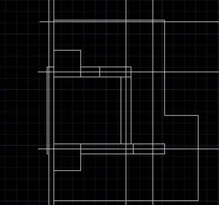
STEP 5:
- Enter L in command box
- Enter 4’ as offset distance
- Enter 4.5” on either side
- Enter 2’6” on upper side, down side, left side and right side
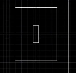
STEP 6:
- Enter O in command box
- Enter 5’-7 ½” as offset distance
- Enter 9” as length and 18” as width
- Enter 3’ on either sides
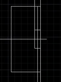
STEP 7:
- Enter O in command box
- Enter 5’-7 ½” as offset distance
- Enter 4.5” below line
- Enter 24” and connect it
- Enter 19.5” above
- Enter 3’ below it
- Enter 2’ at right side
- Enter 3’ above it
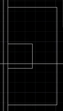
STEP 8:
- Enter O in command box
- Enter 7’ as offset distance
- Enter 4.5” at right side and 23.5” at left side
- Enter 2’6” at right side and upper side
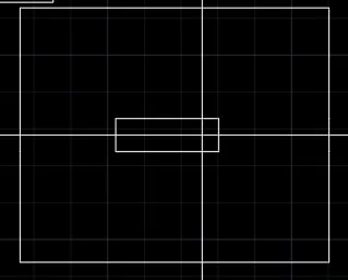
STEP 9:
- Enter L in command box
- Enter 4.5” on either side of 5’7 ½” line
- Enter 9” on either side of 3’9” line
- Enter 2’6” below it
- Enter 2’6” after the rectangle
- Enter 3’ above it
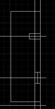
STEP 10:
- Enter L in command box
- Enter 4.5” at right side
- Enter 9” at top side
- Enter 23.5” at left side and close it
- Enter 2’6” at right side, left side, upper side and lower side
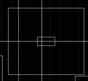
STEP 11:
- Enter L in command box
- Enter 4.5” on either side of 7’ line
- Enter 2’6” on all sides
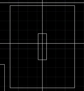
STEP 12:
- Enter L in command box
- Enter 4.5” above 5’ 7 ½” above it
- Enter 19.5” below
- Enter 3’ below rectangle
- Enter 2’ after square
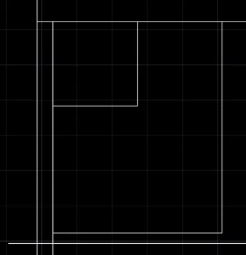
STEP 13:
- Enter L in command box
- Enter 28” as length and 9” as width
- Place it tracking previous rectangle
- Enter 2’6” on either side
- Enter 3’ at lower side
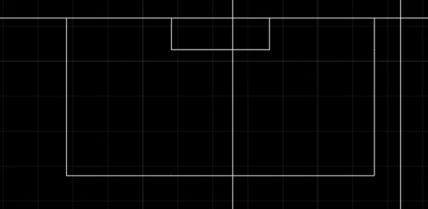
STEP 14:
- Enter L in command box
- Enter 4.5” at right side and 13.5” at left side
- Enter 2’6” at left side and lower side
- Enter 2’6” after 5’7 ½” line
- Enter 4.5” above 3’7 ½” line
- Enter 19.5” below it
- Enter 2’6” below it
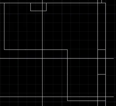
STEP 15:
- Enter H in command box
- Click ANSI37 with 1” spacing
- Click AR-CONCRETE with 0.05” spacing
- Click ANSI32 with 1” spacing
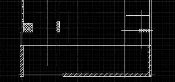
STEP 16:
- Click LAYER PROPERTIES
- Click NEW LAYER
- Enter RAFT in NAME
- Select ACAD_ISO08W100 as LINETYPE
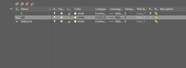
STEP 17:
- Enter DIMS in command box
- Click MODIFY. In SYMBOLS and ARROWS, Enter ARROW SIZE as 11”.
- In TEXT, Enter TEXT HEIGHT as 11”.
- In PRIMARY UNITS, Click DECIMAL in UNIT FORMAT, 0 in PRECISION.
- In LINES, Enter 1” as EXTEND BEYOND LINES and 1” as OFFSET FROM ORIGIN. Click OK.
- Click SET CURRENT. Click CLOSE.
- Click DIMENSIONS AND TEXT dropdown in LAYER.
- Enter DIML in command box and drag the dimensions.
- Enter DT in command box. Enter 11” as TEXT HEIGHT and 0 as TEXT ROTATION ANGE.
- Enter TEXT.
- Enter CO in command box. Copy the text and place it in another location.
- Enter TEXTEDIT in command box. Using this, editing in text can be done.
- Click the layers to give their properties in diagrams
RESULT:
The Raft layout is created by lines using AutoCAD. The step-by-step procedure for creating Raft layout is also explained. The Dimension is also entered in the diagram.