Creating a Wardrobe detailed drawing, Floor Plan, Kitchen Layout and Column Detail using AutoCad
Q1
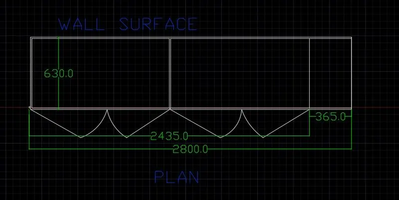
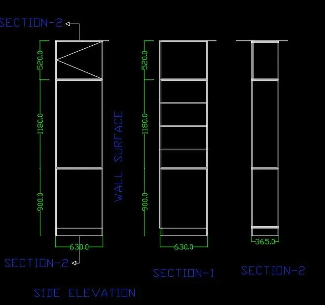
Step1: The plan of the wardrobe is drawn with the help of horizontal and vertical construction lines. The doors of these cabinets are drawn with the help of arc and line command as shown in the figure.
Step2: The front elevation of the same is drawn of the same size and with the help of line command it is achieved.
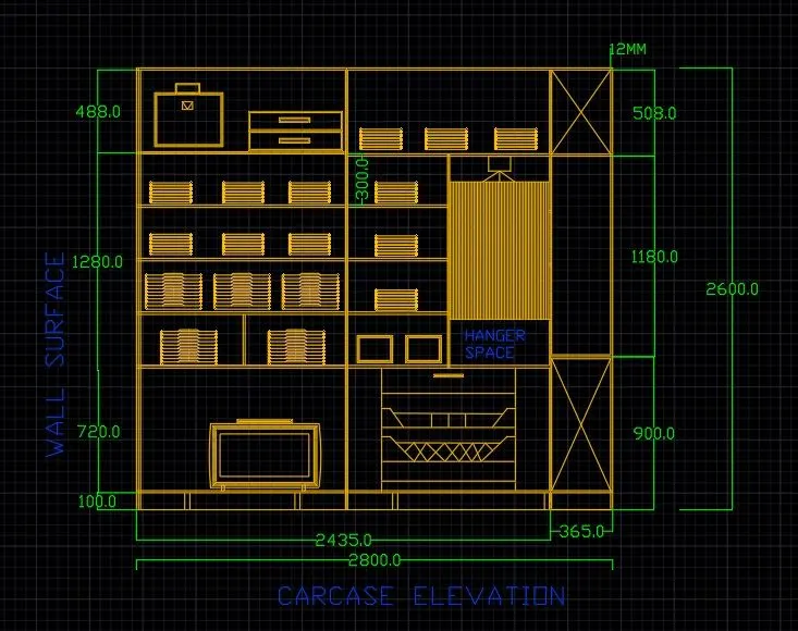
Step3: The elevation of the carcase is drawn with the help of various tools such as line to draw the outer casing. And copy tool in order to replicate the item repetition in the wardrobe.
Step4: The side elevations and the sections are dawn with the help of line and offset tolls similarly.
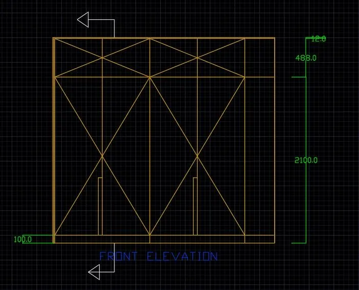
Step5: The dimension and the text are mentioned in different layers for easy identification.
Step6: The unwanted lines are trimmed and deleted later.
RESULT
Q2
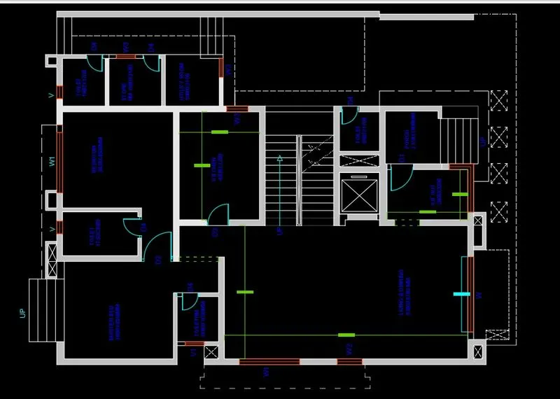
Step1: The outer line of the plan is first marked with the help of horozontal and vertical construction lines.
Step2: An offset of 230mm for external walls and 150mm for internal walls are drawn.
Step3: Based on the dimensions of the rom mentioned another offset is drawn for which a wall offset of either 150 or 230mm is drawn to create a room of the requiured dimension.
Step4: The doors are drawn witht the help of arc tool.
Step5: The dotted lines are drawn by selection the line type and adjusting the scale of the line as well.
Step6: The outer sitting table is drawn with the help of circle, line and arc tools.
Step7: The unwanted lines and trimmed and deleted later.
RESULT
Q3
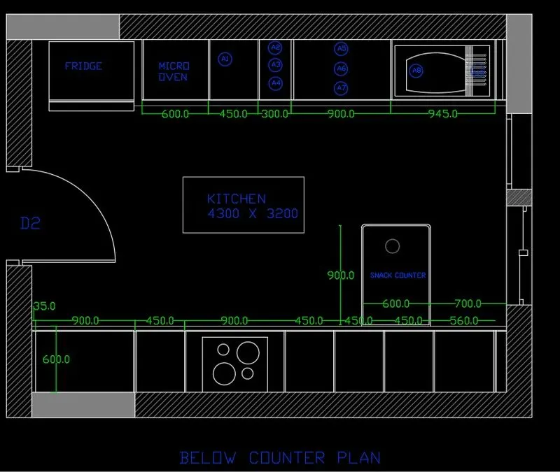
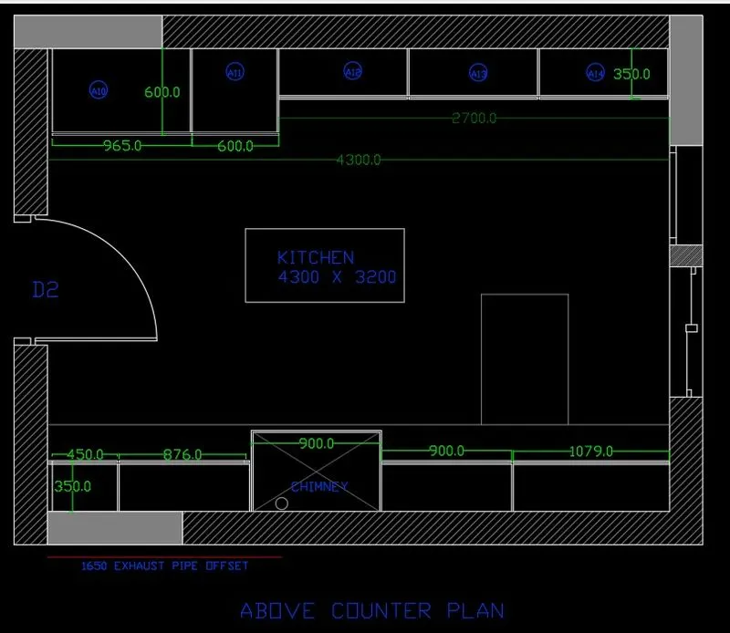
Step1: The outer edges of the kitchen pland are marked with the help of horizontal and vertical construction lines.
Step2: An offset of 230mm is drawn to mark the walls of the kitchen.
Step3: The counters in the kitchen is drawn with offset again and the required segments are created as per the dimensions.
Step4: This is then copied to create the top part of the kitchen area and the couter regions are edited as the dimesions.
Step5: The hatching is provided with the help of hatch command to mark the wall region.
Step6: The extra and unwanted lines are trimmed and deleted later.
RESULT
Q4
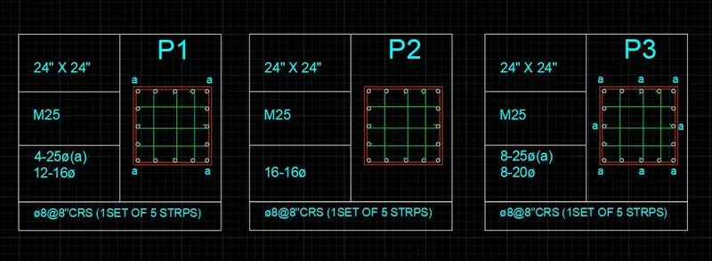
The column schedule shown here is drawn with the help of the following tools:
Step 1: The Columns are drawn of the mentioned size 24"x24" and an offset is provided for the tie to be provided.
Step 2: The rebars provided are drawn with the help of circle tool and is copied and mirrored around the tie equally to provide the required number of bars.
Step 3: A table is created as shown to mention the size, grade of concrete and also the rebar provided.
Step 4: The same is copied for P2 and P3 and required changes are made.
RESULT
Q5
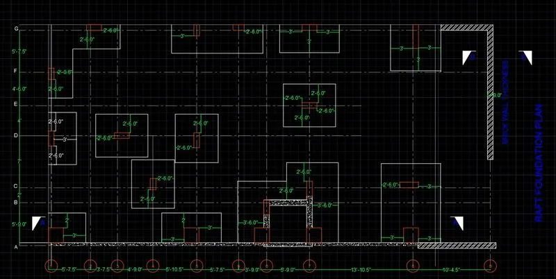
The Raft foundation is drawn as follows:
Step 1: Grid lines as per the measorements are drawn in order to locate the columns exactly
Step 2: The columns are drawn as per the specifications measuring from the grid lines.
Step 3: The footing for the columns are drawn by drawing rectangulars or the measured sizes and placing them over the columns at the reuired locations.
Step4: The catilever distances from the column edges are adjusted wherever required.
Step 5: The extra grid lines and footing lines are trimmed and deleted.
Step 6: Hatching is provided to mention the wall and retaining wallforthe raft.
RESULT-