Creating a Wardrobe detailed drawing, Floor Plan, Kitchen Layout and Column Detail using AutoCad
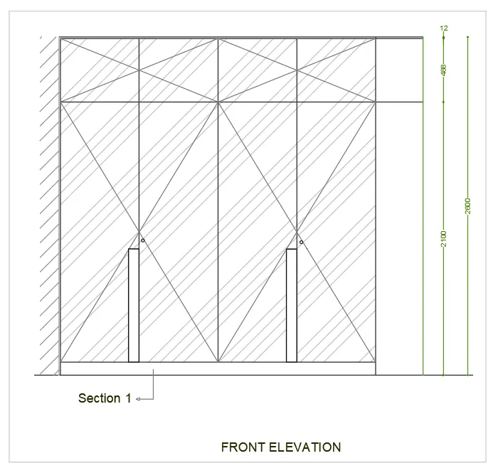
1. AIM : To Draw the elevation and details of a wardrobe as shown in the Figure below. After sketching,
you need to provide the dimensions and text with the use of layers. Use proper text styles and
dimension methods to document it. Also, assume dimensions, wherever needed.
- Open the Autocad
- Type unit and selet the decimal unit and precission as 0.0
- Type limits ans specify the lower and upper limits
- Type Z (Zoom) enter and A enter.
- Start for drafting
- All Dimensions are in mm
COMMAND USED :
- Limits
- Zoom
- Xline
- Line
- Circle (C) command
- X (Explode) Command
- Dimlinear
- Dimcont
- DT command
- ED command
- MT Command
- Unit command
- LW command
- H (Hatch)
- HE (Hatch Edit)
- Offset
- Arc
- Extend command
- Trim command
STEP WISE PROCEDURE :
Step - 1 (FRONT ELEVATION)
- Start with line command (L)
- Unit and Grid set 1 and 1
- Enter the xline command : 1,1
- Draw the line in both X and Y axis
- Type L enter and specify the point with ortho on draw in X direction-2800 and in Y direction 2600
- Run command offset (O)
- Offset (O) in X direction 12 enter
- Offset in X direction 1223 enter
- Offset in X direction 1200 enter
- Offset in X direction 365 enter
- Offset from bottom line 100 enter
- Offset 611.5 enter
- Offset 600 enter
- Inter Hatch (H) command from ribbon bar and do the hatching
- Hatch Edit and change hatching as per required drawing
- Trimmed all extra line as as fig. with command (TRIM)
- Front Elevation is obtained
- All works done with different layers shown in different colours
RESULT - Step - 1 (FRONT ELEVATION)
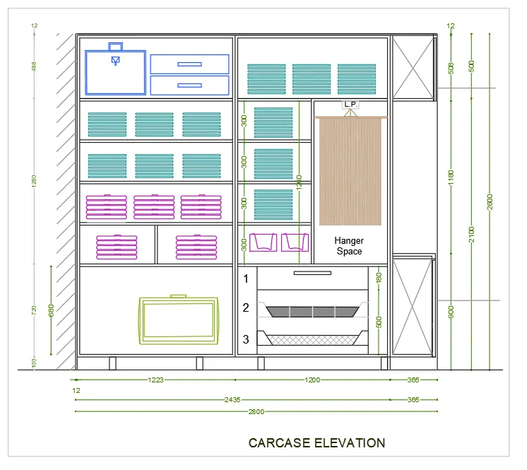
Step - 2 (CARCASE ELEVATION)
- Start with line command (L)
- Unit and Grid set 1 and 1
- Enter the xline command : 1,1
- Draw the line in both X and Y axis
- Type L enter and specify the point with ortho on draw in X direction-2800 and in Y direction 2600
- Run command offset (O)
- Offset (O) in X direction 12 enter
- Offset in X direction 1223 enter
- Offset in X direction 1200 enter
- Offset in X direction 365 enter
- Offset from bottom line 100 enter
- Offset 20 enter
- Offset 680 enter
- Offset 20 enter
- Offset 300 enter
- Offset 20 enter
- Offset 300 enter
- Offset 20 enter
- Offset 300 enter
- Offset 20 enter
- Offset 300 enter
- Offset 20 enter
- Offset 488 enter
- Offset 12 enter
- Trim all extra line as per drawing
- Draw a line at the mid point of the cabinet space second right of the cabinet from bottom
- Select the layer option and insert new layer as cloths
- with the help of line, circle and polyline command and draw the folded cloths as shown in the fig.
- Command LA and insert new layer as bags
- Type dimstyle in the command prompt and go to symbols and arrow and select arrow heads as dot small and enter
- Give the desired dimention with help of dimension command (DIMLIN)
- Command DT and single line and type hange space
- Carcase elevation is obtained from the following
- All works done with different layers shown in different colours
RESULT - Step - 2 (CARCASE ELEVATION)
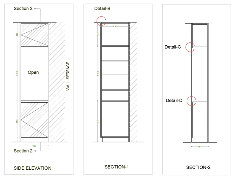
Step - 3 (Side Elevation, Section 1 and Section 2)
- Draw a side elevation draw a line of 630 in X axis and 2600 in Y axis
- Type offset (O) enter and type 900
- Offset 1180 enter
- Offset 520 enter
- Select the hatching properly with H command and do the hatching
- Use the text command and right the wall surface
- For Section 1
- Draw a side elevation draw a line of 630 in X axis and 2600 in Y axis
- Use Offset command (O) and type 900 enter
- Offset 300 enter
- Offset 520 enter
- For Section 2
- Draw a side elevation draw a line of 365 in X axis and 2600 in Y axis
- Type offset (O) command and type 900 enter
- Offset 1180 enter
- Do the finish the drawing and shown final result
RESULT - Step - 3 (Side Elevation, Section 1 and Section 2)
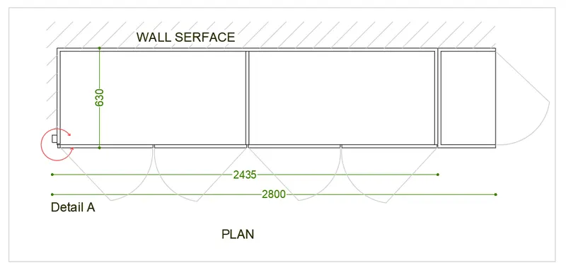
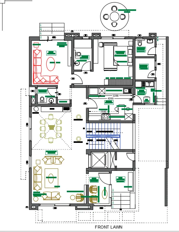
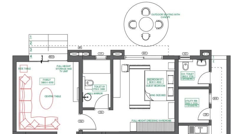
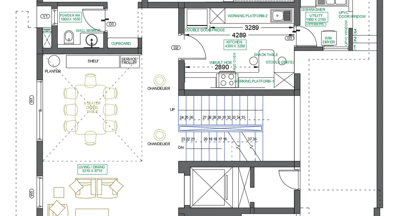
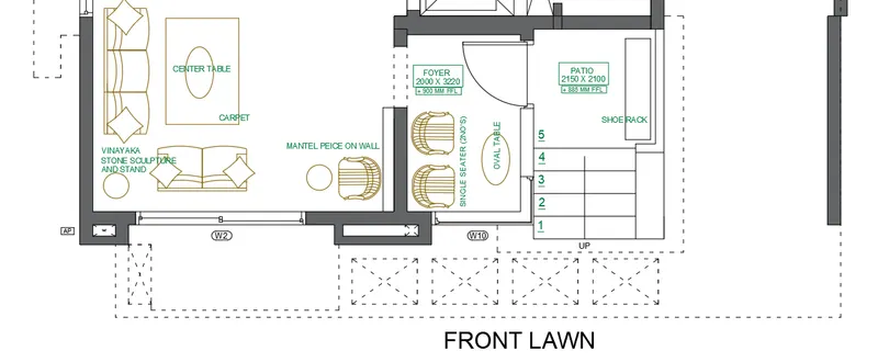
2. AIM : To Draw the floor plan as shown in the Figure. Use the proper drafting tools to sketch the plan. Do not hatch
or draw the furniture. You need to draw the floor plan with the following:
Note: You can also import the Floor_Plan.pdf into your current drawing and start working on the project.
You need to scale the imported pdf file using reference option. All dimensions are in mm.
- Walls (Exterior and Interior)
Wall Thickness: Exterior Wall- 230mm, Interior Wall: 150 mm (Wherever Required)
- Doors and Windows: Assume the size of the doors and window.
2.1 Stairs: Tread-300mm, Riser-150mm
- Insert Text wherever required
- Insert the dimensions using proper dimension techniques
- Open the Autocad
- Type unit and selet the Decimal unit and precission as 0.0
- Type limits ans specify the lower and upper limits
- Type Z (Zoom) enter and A enter.
- Start for drafting
- All Dimensions are in mm
COMMAND USED :
- Limits
- Zoom
- Xline
- Line
- Circle (C) command
- X (Explode) Command
- Dimlinear
- Dimcont
- DT command
- ED command
- MT Command
- Unit command
- LW command
- H (Hatch)
- HE (Hatch Edit)
- Offset
- Arc
- Extend command
- Trim command
STEP WISE PROCEDURE :
Step - 1 (FRONT ELEVATION)
- Start with line command (L)
- Unit and Grid set 1 and 1
- Enter the xline command : 1,1
- Draw the line in both X and Y axis
- Type L enter and specify the point with ortho on draw in X direction-13000 and in Y direction 16470
- Run command offset (O)
- Offset (O) in X direction 230 enter
- Offset 3880 enter
- Offset 150 enter
- Offset 1750 enter
- Offset 150 enter
- Offset 3830 enter
- Offset 150 enter
- Offset 1900 enter
- Offset 4350 enter
- Offset 1650 enter
- Offset 3200 enter
- Offset 3220 enter
- Offset 1600 enter
- All the Inner wall make 150mm offset and draw the offset
- With the line type select dotted line and make the front lown portion with the help of line command
- Draw the stair with 300 tread with offset command
- Draw the door with the help of ine command and circle
- Trim and excess circle and line
- Draw the window with the help of line command with ortho on. where ever mentioned in the drawing
- Draw the toilet with the help of polyline and line commanbd
- Select the text (MT) command and write down the details such as bedroom, toilet and its dimension
- Trim all the intersecting line in the all corners of the line and join the lines where ever necessary
- Draw the kitchen counter slab to the length of 2890 in X direction and 500 in Y direction
- Use fillet command to join the corner of the two lines for curved finish
- Draw the cut outs with the help of line command
- Draw the ventilators where ever required
- Draw the planter box with help of the line command of width 1075mm
- Draw a line at the midpoint
- Desired drawing is obtained
- All works done with different layers shown in different colours
RESULT
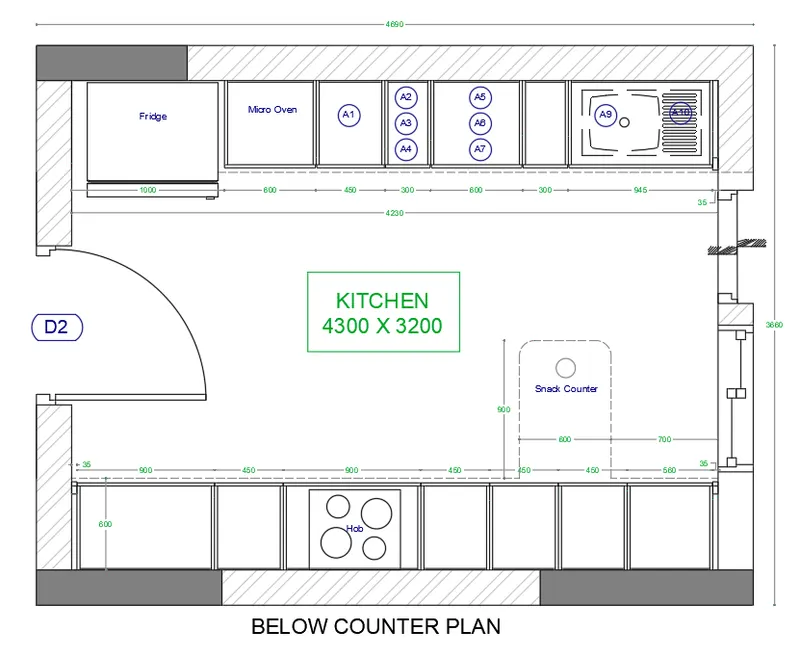
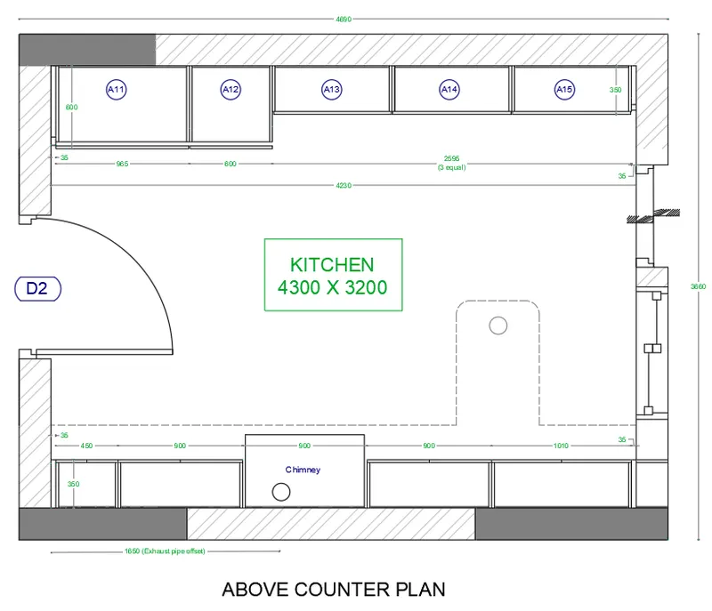
3. AIM : To Create the Kitchen Layout as shown in the Figure below. Also, use proper dimension techniques to
dimension the kitchen layout. Also, insert text wherever required. All dimensions are in mm.
- Open the Autocad
- Type unit and selet the Decimal unit and precission as 0.0
- Type limits ans specify the lower and upper limits
- Type Z (Zoom) enter and A enter.
- Start for drafting
- All Dimensions are in mm
COMMAND USED :
- Limits
- Zoom
- Xline
- Line
- Circle (C) command
- X (Explode) Command
- Dimlinear
- Dimcont
- DT command
- ED command
- MT Command
- Unit command
- LW command
- H (Hatch)
- HE (Hatch Edit)
- Offset
- Arc
- Extend command
- Trim command
STEP WISE PROCEDURE :
Step
- Start with line command (L)
- Unit and Grid set 1 and 1
- Enter the xline command : 1,1
- Draw the line in both X and Y axis
- Type (L) enter and specify the point draw in X direction 4300 and in Y direction 3200
- Offset 230 enter in X direction
- Draw a line 4230 in X direction and 600 in Y direction for Slab
- Type offset (O) 35 enter in X direction
- Offset 900 enter in X direction
- Offset 450 enter in X direction
- Offset 900 enter in X direction
- Offset 450 enter in X direction three times
- Offset 560 enter in X direction
- Draw the snack counter of 900 in Y direction and 600 in X direction with help of dashed line
- Draw a circle in the snack counter (middle of left and right)
- Draw the offset on the other side also with the offset
- Type (O) command and type 1000 in X direction (Space for Fridge)
- Offset 600 in X direction (Micro Oven)
- Offset 450 in X direction
- Offset 300 in X direction
- Offset 600 in X direction
- Offset 300 in X direction
- Offset 945 in X direction
- Offset 35 in X direction the help of dimension command dimlin and dimcont
- Do the hatching with (H) com the millor command and select the object and do the mirror of the same drawing and keep the original
- Do the offset as per the drawing
- Insert the text command and do the detailing
- Draw circle in each cabinet and type the details as mentioned in fig.
- All works done with different layers shown in different colours
RESULT
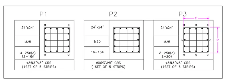
4. AIM : To Sketch the column details as shown in Figure. Insert dimensions and text in the figure. Refer to the bar
sizes from the schedule.
8mm ---- 0.31 Inches
25mm--- 1 inches
16mm—0.62 inches
- Open the Autocad
- Type unit and selet the Architectural unit and precission as 0.0
- Type limits ans specify the lower and upper limits
- Type Z (Zoom) enter and A enter.
- Start for drafting
- All Dimensions are in inch Architectural
COMMAND USED :
- Limits
- Zoom
- Xline
- Line
- Circle (C) command
- X (Explode) Command
- Dimlinear
- DT command
- ED command
- MT Command
- Unit command
- Offset
- Extend command
- Trim command
STEP WISE PROCEDURE :
Step
- Start with line command (L)
- Unit and Grid set 1" and 1"
- Enter the xline command : 1,1
- Draw the line in both X and Y axis
- Draw a square using REC command of 24' x 24"
- Offset inner side 0.5" of box
- Explode (X) command for box
- Make a circle with tan tan radius 1 on the corner
- divide command for do the 4 part of column size
- Copy the circle and paste as per drawing
- Type DO command and fill the circle the reinforcement rod
- Join the circle with line as per drawing
- make the hook and per drawing
- F (Fillet) command for corner rounded 0.5"
- Using text command for write the details as given
- Copy the entire object and paste and edit the details such as 16-16 dia and so on
- All three required columns schedule is obtained as per drawing
- All works done with different layers shown in different colours
RESULT
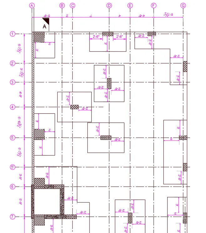
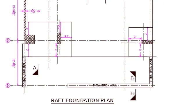
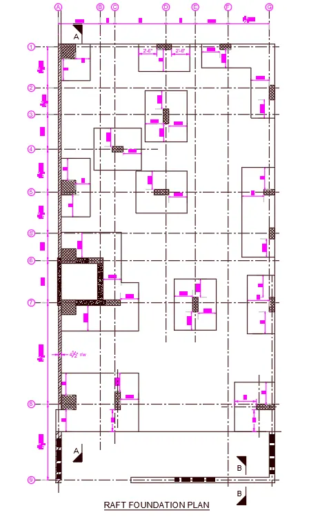
5. AIM : To Draw the Raft Layout as shown in the Figure. Assume the column size as per your knowledge.
You can take the sizes as: 24”x24”, 9” x 24”, 9” x 18”, and 9’ x 24”. You can import the raft_foundation.pdf
to ensure the missing dimensions.
- Open the Autocad
- Type unit and selet the Architectural unit and precission as 0.0
- Type limits ans specify the lower and upper limits
- Type Z (Zoom) enter and A enter.
- Start for drafting
- All Dimensions are in inch Architectural
COMMAND USED :
- Limits
- Zoom
- Xline
- Line
- Circle (C) command
- X (Explode) Command
- Dimlinear
- Dimcont
- Hatch (H)
- Hatch Edit (HE)
- DT command
- ED command
- MT Command
- Unit command
- Offset
- Extend command
- Trim command
STEP WISE PROCEDURE :
Step
- Start with line command (L)
- Unit and Grid set 1" and 1"
- Enter the xline command : 1,1
- Draw the line in both X and Y axis
- Offseet in X Direction 5'-9", 2', 7', 4', 4'-6", 5'-7.5"
- Offset in Y Direction from the same point draw a horizontal line and start offset command
- Offset 5'-7.5", 3'-7.5", 4'-9", 5'-10.5", 5'-7.5", 3'-9", 5'-9", 13'-10.5" and 10'-4.5"
- Dimensions of the columns are not given so, their dimensions can be assumed 24"x24", 9"x30", 9"x18", 9"x24"
- In the first column provided at the middle top, take an offset of 2'-6" from the left side and right side and 3' at the bottom.
- Repeat same procedure to mark the footing of columns throughout the fig.
- Draw line of 9" thick and hatch it with brickwork hatch
- On the grid by right clicking on the grid and then given the spacing between the grids
- All works done with different layers shown in different colours
RESULT