Creating a Wardrobe detailed drawing, Floor Plan, Kitchen Layout and Column Detail using AutoCad
ANSWERS FOR CHALLENGE
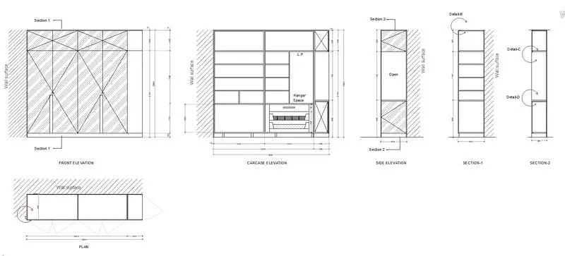
1. Draw the elevation and details of a wardrobe as shown in the Figure below. After sketching, you need to provide the dimensions and text with the use of layers. Use proper text styles and dimension methods to document it. Also, assume dimensions, wherever needed.
Note: All dimensions are in mm.
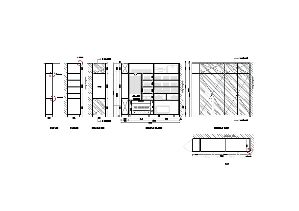
1.Ans:-AIM:
To draw the elevation and details of wardrobe.
COMMANDS USED:
- Limits command
- Line command
- Offset command
- Hatch command
- Dimlinear command
- Dimstyle command
- Units command
PROCEDURE:
STEP-1
FRONT ELEVATION:
- First we have to draw the line with line command of length 2800mm and draw a line.
- Next divide the vertically 5 times.
- Next take the offset command and offset the horizontal line from the top with the length of 500mm.
- Again offset line to 12mm, and again offset the line from bottom of length 20mm.
- Next draw the line crossly from 1 vertical line top to the third line bottom.
- Do this step continuously when the figure completes the drawing.
- Next we have to hatch and put the dimensions for every part in the figure. . And we have to enter the text for required part in the figure.
SECTION 1
Step:-1
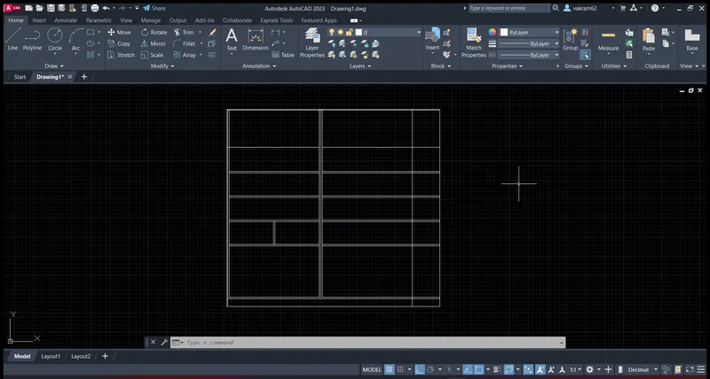
Carcase elevation:
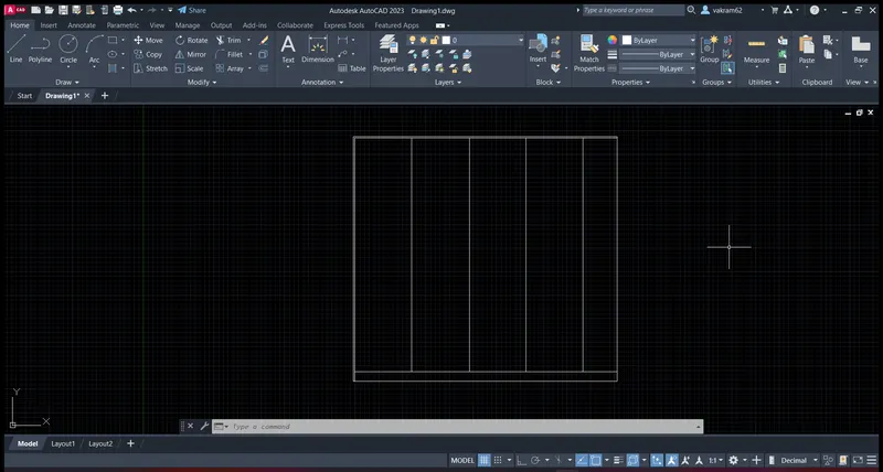
- First we have to draw the line with line command of length 2800mm and draw a line again upwards with the length of 2600mm . And next we have to draw the line backwards from the right corner of top with the length of 2800mm.
- Then next join first line and the last line
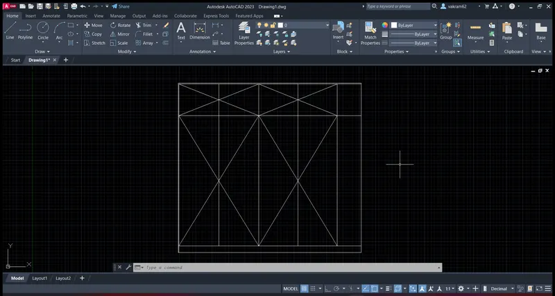
- Next we have to divide the selves in the wardrobe into 6 parts vertically, and divide three parts horizontally.
- Now hatch the all parts in the carcase elevation
- Now we have to use the trim command to trim the unwanted lines and objects.
- Now the different selves are created as shown in the figure below.
- Using the line command and offset command we draw the different parts in the wardrobe as shown in the figure below.
- Finally we put the dimensions for every part in the diagram as we drawn below.
Step: 2
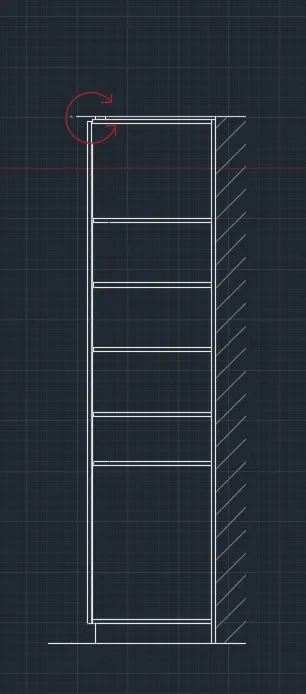
Side elevation:
- Next we have to draw the side elevation in detail.
- First we have to draw the line using line command with the length of 630mm horizontally forwards. . And again draw the line vertically upwards with the length of 2600mm from the previous line drawn.
- Next again draw the horizontal line backwards from the top with the length of 630mm.
- And join the first line and the last line which have drawn previously.
- After the offset the bottom line with the length of 20mm. Similarly make the offset to all the sides in the figure.
- Next use the hatch command to hatch, and put the dimensions where requires. And we have to put the dimensions for every part in the figure
Step:-3
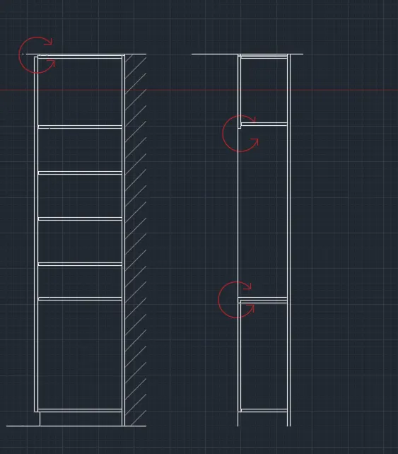
Section-1
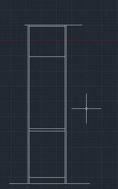
- Next we have to draw the section-1 in detail.
- First we have to draw the line using line command with the length of 630mm horizontally forwards
- And again draw the line vertically upwards with the length of 2600mm from the previous line drawn.
- Next again draw the horizontal line backwards from the top with the length of 630mm.
- And join the first line and the last line which have drawn previously. Next divide the six parts from bottom to top with different dimensions.
- After the offset the bottom line with the length of 20mm. . Similarly make the offset to all the sides in the figure.
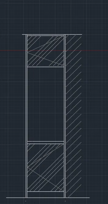
- Next use the hatch command to hatch, and put the dimensions where requires
- And we have to put the dimensions for every part in the figure.
- And we draw the detail B at the top of the left corner shown in figure
- Next divide the three parts from bottom to top with different dimensions. After the offset the bottom line with the length of 20mm.
- Similarly make the offset to all the sides in the figure. And we have to put the dimensions for every part in the figure.
- And we draw the detail-C and detail-D at middle part of the both left corners shown in figure. Now we draw the cross lines in the first part and third part of the figure.
Step: 4
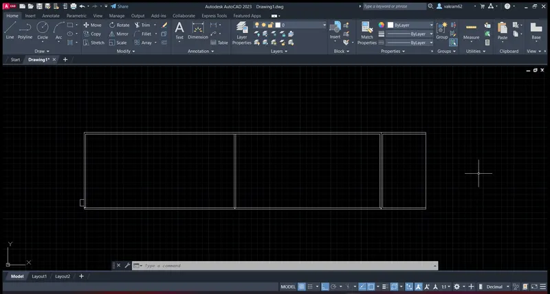
Plan:
- First we have to draw the length of 2800mm. And next we have to draw the length of 630mm upwards vertically.
- Then again draw the length of 2800mm backward horizontally. Next join the first line and the last line which we drawn previously.
- Next use the offset command to offset the all sides of the figure to inside, and the offset of length 20mm.
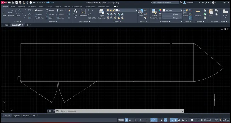
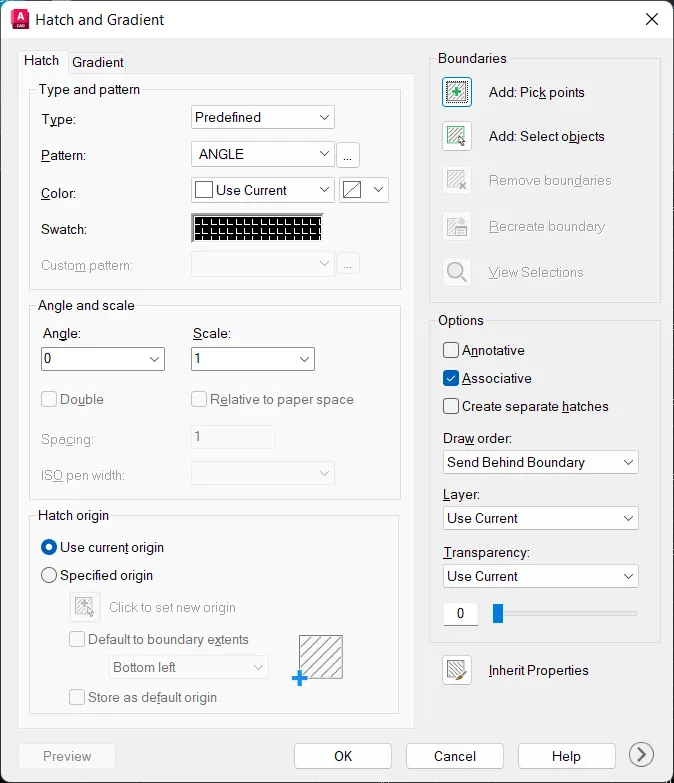
- Next use the hatch command to hatch the outer side of a figure, that outer side is a wall surface.
- And we draw the Detail-A at the left side comer of the figure at the bottom as shown in figure.
- Finally we have to put the dimensions for every part in the figure.
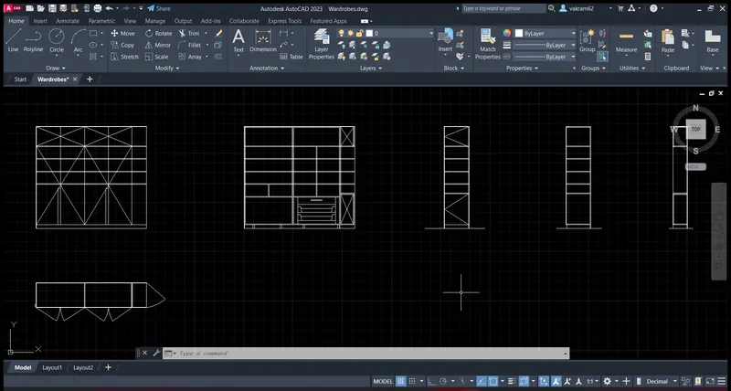
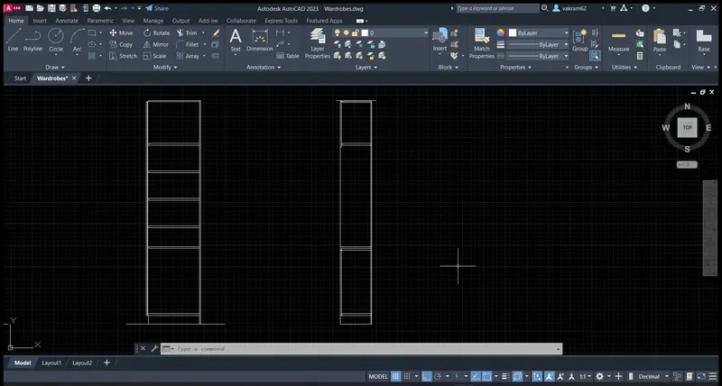
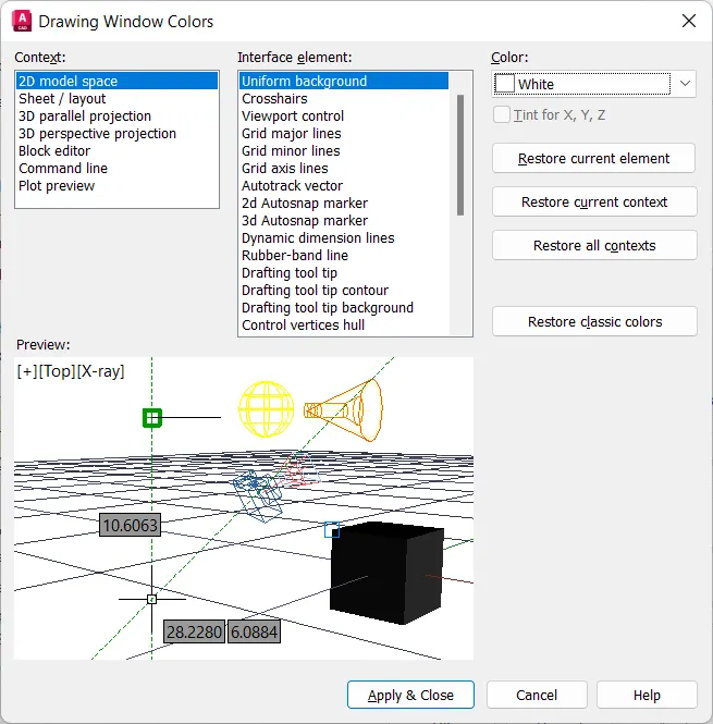
Changing background colour
RESULT:
The elevation, plan and details are created successfully using autocad.
Q2. Draw the floor plan as shown in the Figure. Use the proper drafting tools to sketch the plan. Do not hatch or draw the furniture. You need to draw the floor plan with the following:
Note: You can also import the Floor_Plan.pdf into your current drawing and start working on the project. You need to scale the imported pdf file using reference option. All dimensions are in mm.
- Walls (Exterior and Interior)
Wall Thickness: Exterior Wall- 230mm, Interior Wall: 150 mm (Wherever Required)
- Doors and Windows: Assume the size of the doors and window.
2.1 Stairs: Tread-300mm, Riser-150mm
- Insert Text wherever required
- Insert the dimensions using proper dimension techniques
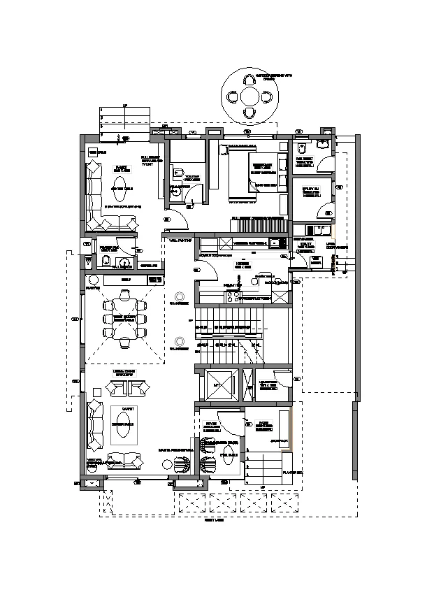
2.Ans: To draw floor plan layout with the use of AutoCad tools.
Note: Hatch and furniture not drawn as per mentioned in quetion
Used commonds:
1.Xref : for importing the pdf file.
2.Dimension style
3.Scale: for scale the pdf to actual dimensions
4.Layers
Procedure:
Step-1
- Open new file drawing,and set the primary unirts as metric
- Enter the XREF command
- Scale it to actual daimentions
- Enable the snap
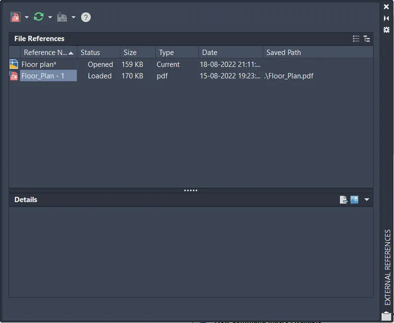
Step-2
- Enter the line commond
- Start the tracking the points
- Requered point to be drawn
Step-3
- Enter the layers command
- Specify the all text and dimensions
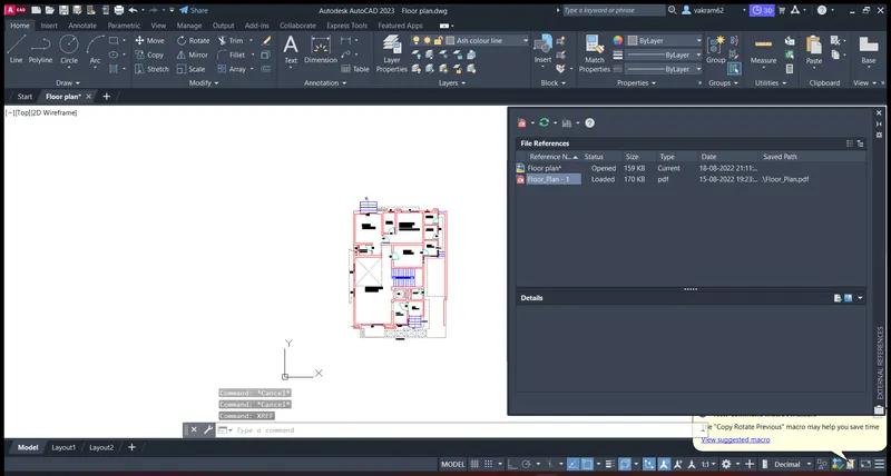
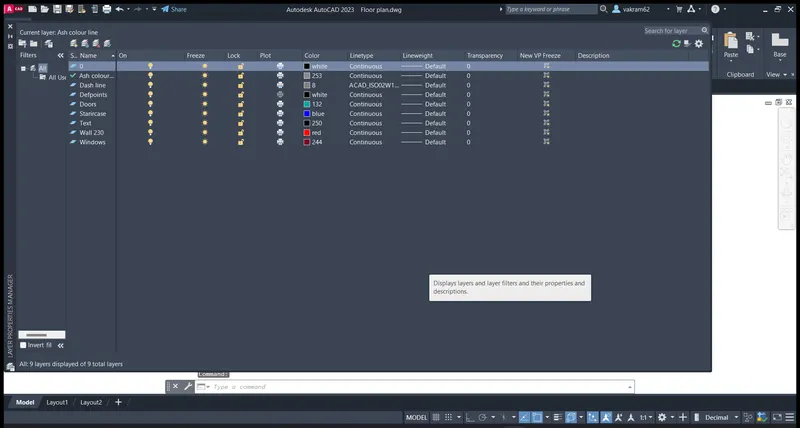
Result: Floor plan drawn successfully as per given layout
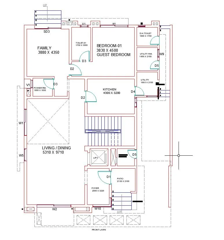
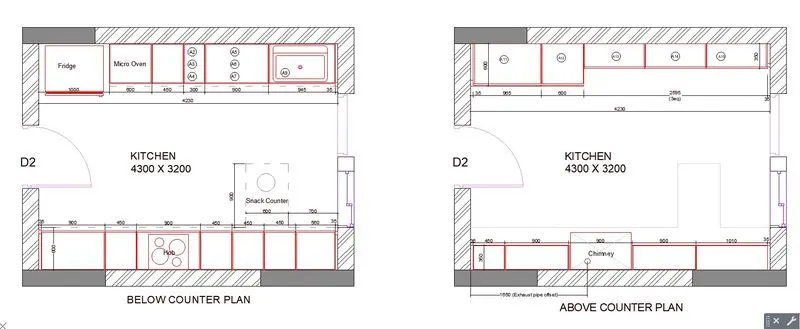
Q3. Create the Kitchen Layout as shown in the Figure below. Also, use proper dimension techniques to dimension the kitchen layout. Also, insert text wherever required. All dimensions are in mm.
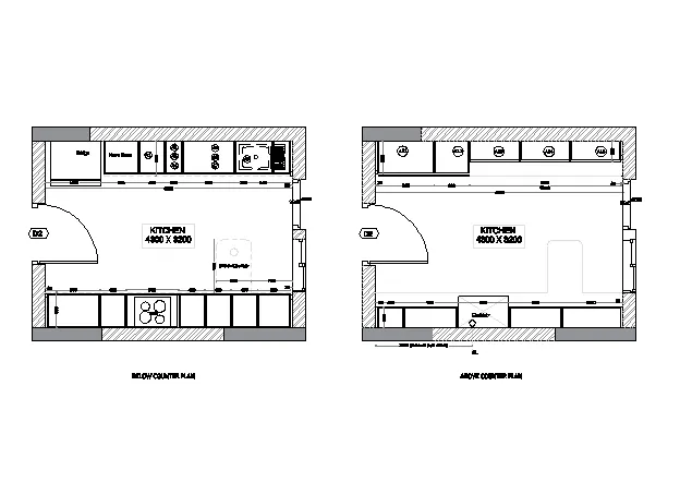
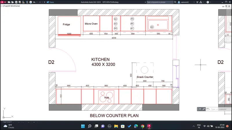
3)ans: KITCHEN LAYOUT
AIM: To create the kitchen layout using AutoCAD.
INTRODUCTION: The kitchen layout using AutoCAD is created by Lines and Circles. The procedure and result should be written after creating the kitchen layout.
(a)BELOW COUNTER PLAN
PROCEDURE:
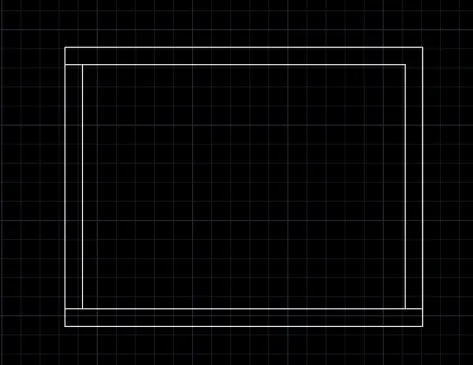
STEP 1:
- Open the AutoCAD software and click start Drawing tab.
- Enter UNITS in command box.
- Select DECIMAL in TYPE, 0 in PRECISION and MILLIMETERS in UNITS TO SCALE INSERTED CONTENT. Press OK.
- Switch on ORTHOMODE.
- Enter L and type 0,0 in command box.
- Type @4690,0 in command box.
- Type @ 0,3660 in command box.
- Type @-4690 in command box.
- Type @0, -3660 in command box.
- Enter O in command box
- Enter 230 as offset distance
- Place it at four sides
- Enter TR in command box
- Delete the unwanted lines
STEP 2:
- Enter L in command box
- Enter 35 as first point
- Enter 50 as next point
- Enter 35 as next point
- Enter O in command box
- Enter 600 as offset distance
- Enter 4230 as next point
- Click it at midpoint of 35
- Connect it at other end
- Click the midpoint and connect it at bottom
- Create an offset of 20
- Create offset at 3 sides
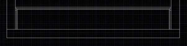
STEP 3:
- Create offset as 900, 450, 900, 450, 450, 450 and 560
- Create offset at 20
- Select the line and create offsets
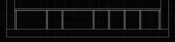
STEP 4:
- Enter L in command box
- Enter 100 as first point
- Enter 550 as next point
- Enter 700 as next point
- Enter 550 as first point
- Enter C in command box
- Enter 200 as radius
- Enter 150 as radius
- Copy the circle and place
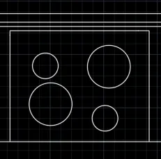
STEP 5:
- Enter L in command box
- Enter 35 as first point
- Enter 50 as next point
- Enter 35 as next point
- Enter O in command box
- Enter 600 as offset distance
- Enter 20 as offset distance
- Enter 900, 945,300,450 and 600 as offset distance
- Enter 20 as offset distance

STEP 6:
- Enter L in command box
- Enter 50 as first point
- Enter 900 as next point
- Enter 700 as next point
- Enter 100 as next point
- Enter 900 as next point
- Enter 100 as next point
- Enter 20 as fillet radius
- Enter L in command box
- Connect it to both sides
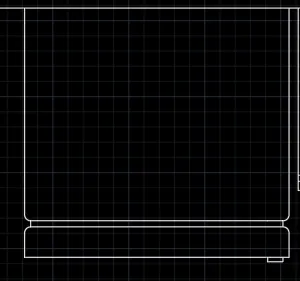
STEP 7:
- Enter L in command box
- Enter 100 as first point
- Enter 75 as next point
- Enter 50 as next point
- Enter 50 as next point
- Enter 25 as next point
- Enter MI in command box
- Copy the mirrored objects
- Place it at other side
- Enter C in command box
- Place the circle at the appropriate place
- Enter TR in command box
- Delete the unwanted lines
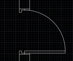
STEP 8:
- Enter L in command box
- Enter 100 as first point
- Enter 115 as next point
- Enter 50 as next point
- Enter 115 as next point
- Enter REC in command box
- Enter 30 as length
- Enter 30 as width
- Copy the squares connecting with lines
STEP 9:
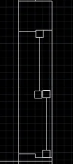
- Enter L in command box
- Enter 50 as first point
- Enter 3735 as next point
- Enter 900 as next point
- Enter 600 as next point
- Enter 900 as next point
- Connect it with the end point
- Enter C in command box
- Enter 30 as radius
- Enter H in command box
- Click ANSI32 as hatch pattern with scale 20
STEP 10:
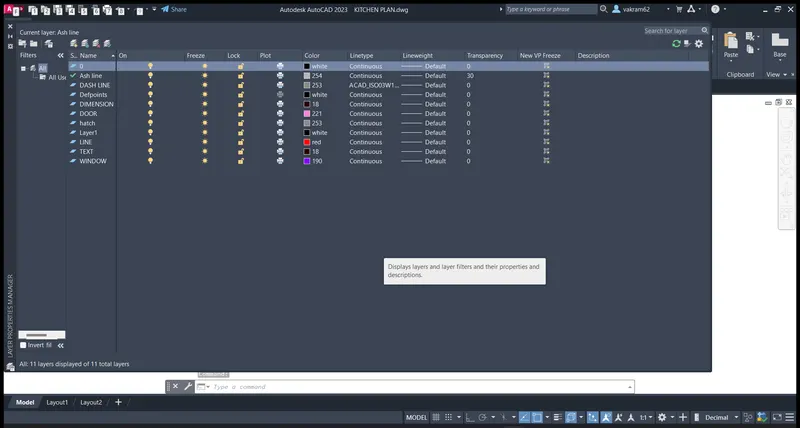
- Click LAYER PROPERTIES
- Click NEW LAYER
- Enter SNACK COUNTER and LAYER in NAME
- Enter ACAD_ISO02W100 for LAYER and ACAD_ISO08W100 for SNACK COUNTER
STEP 11:
- Enter DIMS in command box
- Click MODIFY. In SYMBOLS and ARROWS, Enter ARROW SIZE as 70.
- In TEXT, Enter TEXT HEIGHT as 70.
- In PRIMARY UNITS, Click DECIMAL in UNIT FORMAT, 0 in PRECISION.
- In LINES, Enter 10 as EXTEND BEYOND LINES and 20 as OFFSET FROM ORIGIN. Click OK.
- Click SET CURRENT. Click CLOSE.
- Click DIMENSIONS AND TEXT dropdown in LAYER.
- Enter DIML in command box and drag the dimensions.
- Enter DT in command box. Enter 70 as TEXT HEIGHT and 0 as TEXT ROTATION ANGE.
- Enter TEXT.
- Enter CO in command box. Copy the text and place it in another location.
- Enter TEXTEDIT in command box. Using this, editing in text can be done.
- Click the layers to give their properties in diagrams
(b)ABOVE COUNTER PLAN
STEP 1:
- Copy the outer layer of the kitchen
- Enter L in command box
- Enter 35 as first point
- Enter 450 as offset distance
- Enter 900 as offset distance
- Enter 1010 as offset distance
- Enter 35 as offset distance
- Enter 20 as offset distance
- Create offset distance of 20

STEP 2:
- Enter L in command box
- Enter 100 as first point
- Enter 600 as next point
- Enter 830 as next point
- Enter 600 as next point
- Switch off ORTHOMODE
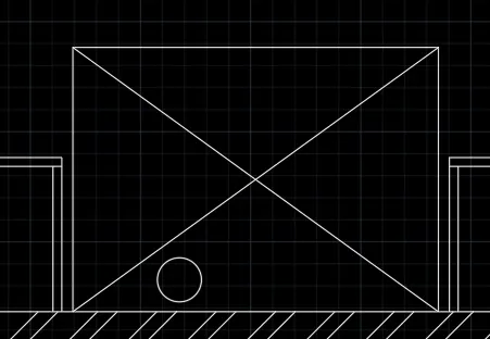
- Create diagonal lines
- Enter C in command box
- Enter 200 as radius
STEP 3:
- Enter L in command box
- Enter 35 as first point
- Enter 350 as next point
- Enter 865 as offset distance
- Enter 20 as offset distance
- Create offsets of 20 at both sides
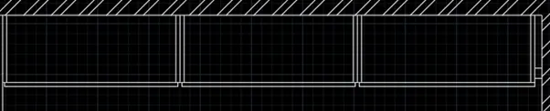
STEP 4:
- Enter L in command box
- Enter 50 as first point
- Enter 600 as offset distance
- Enter 965 as offset distance
- Enter 35 as first point
- Enter 50 as next point
- Enter 35 as next point
- Enter 600 as offset distance
- Enter 20 as offset distance
- Create offsets and select the objects
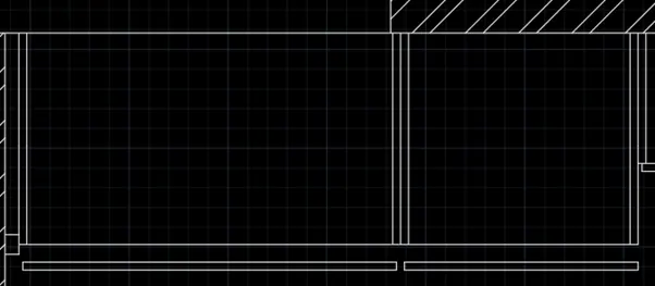
STEP 5:
- Enter DIMS in command box
- Click MODIFY. In SYMBOLS and ARROWS, Enter ARROW SIZE as 70.
- In TEXT, Enter TEXT HEIGHT as 70.
- In PRIMARY UNITS, Click DECIMAL in UNIT FORMAT, 0 in PRECISION.
- In LINES, Enter 10 as EXTEND BEYOND LINES and 20 as OFFSET FROM ORIGIN. Click OK.
- Click SET CURRENT. Click CLOSE.
- Click DIMENSIONS AND TEXT dropdown in LAYER.
- Enter DIML in command box and drag the dimensions.
- Enter DT in command box. Enter 70 as TEXT HEIGHT and 0 as TEXT ROTATION ANGE.
- Enter TEXT.
- Enter CO in command box. Copy the text and place it in another location.
- Enter TEXTEDIT in command box. Using this, editing in text can be done.
- Click the layers to give their properties in diagrams
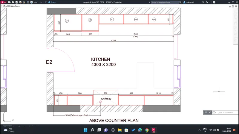
Changing the colour of background
RESULT:
The Kitchen layout is created by lines using AutoCAD. The step-by-step procedure for creating kitchen layout is also explained. The Dimension is also entered in the diagram.
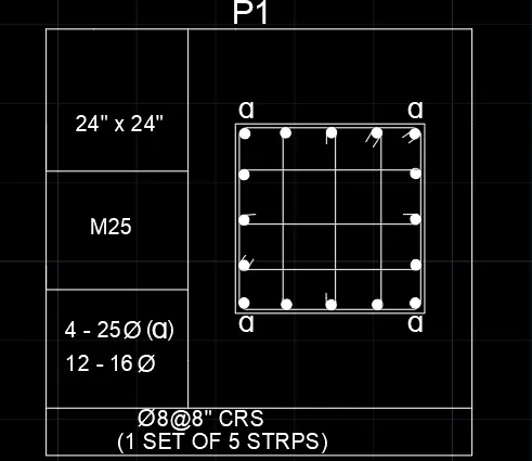
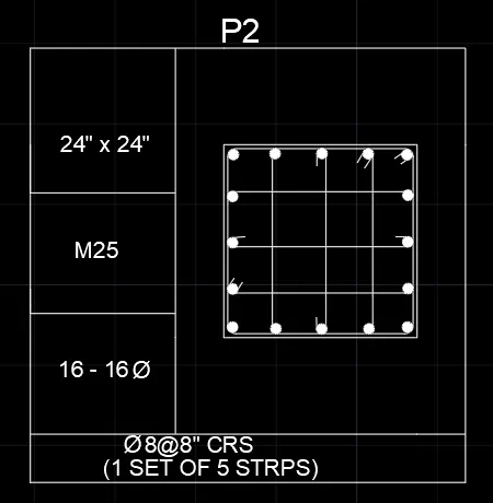
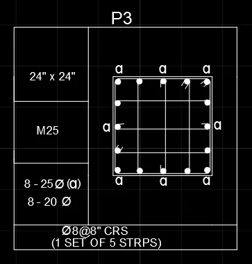
Q4. Sketch the column details as shown in Figure. Insert dimensions and text in the figure. Refer to the bar sizes from the schedule.
8mm ---- 0.31 Inches
25mm--- 1 inches
16mm—0.62 inches
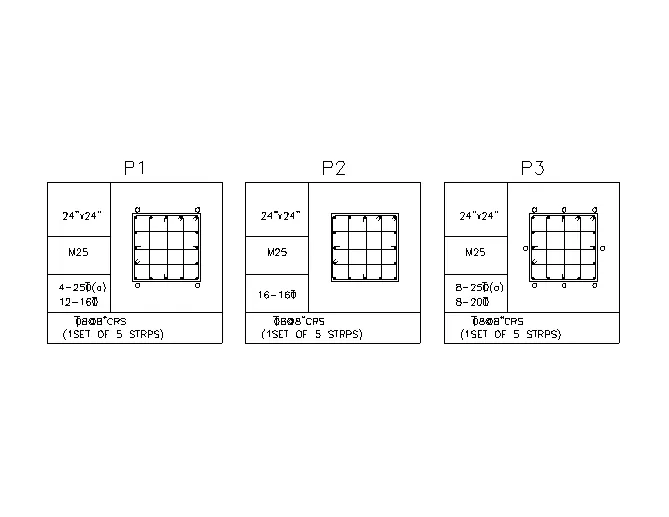
4)ans: COLUMN DETAILS
AIM: To create the column details using AutoCAD.
INTRODUCTION: The column details using AutoCAD is created by Lines and Circles. The procedure and result should be written after creating the column details.
PROCEDURE:
(a)P1
STEP 1:
- Open the AutoCAD software and click start Drawing tab.
- Enter UNITS in command box.
- Select ENGINEERING in TYPE, 0’0” in PRECISION and INCHES in UNITS TO SCALE INSERTED CONTENT. Press OK.
- Switch on ORTHOMODE.
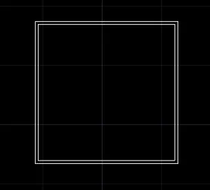
- Enter REC in command box
- Enter 24” as length
- Enter 24” as width
- Enter 0.5” as offset distance
- Select the rectangle and create offset
STEP 2:
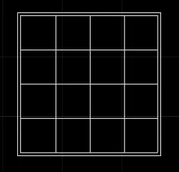
- Enter L in command box
- Enter 5.5 as first point
- Connect it to the end point
- Enter O in command box
- Enter 5.5 as offset distance
- Select the line and create 2 offsets
- Enter L in command box
- Enter 5.5 as first point
- Connect it to the end point
- Enter O in command box
- Enter 5.5 as offset distance
- Select the line and create 2 offsets
STEP 3:
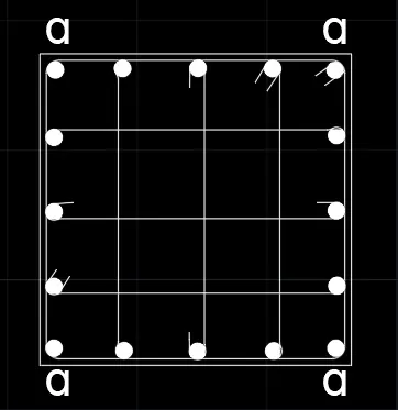
- Enter C in command box
- Enter 0.62” as radius
- Enter CO in command box
- Copy the circle and place at appropriate position
- Enter 1” as fillet radius
- Select the circle and line to create curve shape
- Switch off ORTHOMODE
- Click on the circle and create lines
- Enter DO in command box
- Enter 0 as inner diameter
- Enter 1.24” as outer diameter
- Select MULTILINE TEXT in RIBBON.
- Click SYMBOL and select others.
- Click ARIAL as font and select Latin Small Letter Alpha (U+0251).
- Select it and press ENTER.
- Enter CO in command box and copy it in the required place.
STEP 4:
- Enter REC in command box
- Enter 4’6” as length
- Enter 4’6” as width
- Enter L in command box
- Enter 6” as first point
- Enter L in command box
- Enter 6” as first point
- Enter 1’6” as next point
- Enter 1’ as next point
- Enter O in command box
- Enter 1’3” as offset distance
- Enter O in command box
- Enter 1’6” as offset distance
- Enter DIMS in command box
- Click MODIFY. In SYMBOLS and ARROWS, Enter ARROW SIZE as 1’.
- In TEXT, Enter TEXT HEIGHT as 1’.
- In PRIMARY UNITS, Click ENGINEERING in UNIT FORMAT, 0’0” in PRECISION.
- In LINES, Enter 1’ as EXTEND BEYOND LINES and 1’ as OFFSET FROM ORIGIN. Click OK.
- Click SET CURRENT. Click CLOSE.
- Enter DIML in command box
- Click the points to get dimensions
- Enter DT in command box
- Enter 1’ as text height
- Enter the text
- Use TEXTEDIT AND CO for editing and copying the text
- Click the layers and place it on the dimensions, objects and text
- Save the drawing and rename it as AUTOCAD CHALLENGE 6.
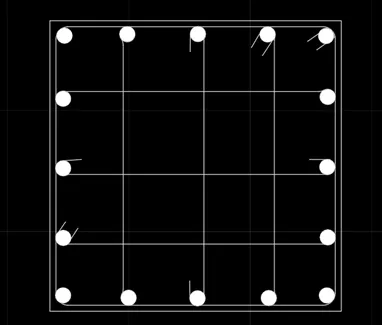
(b)P2
STEP 1:
- Open the AutoCAD software and click start Drawing tab.
- Enter UNITS in command box.
- Select ENGINEERING in TYPE, 0’0” in PRECISION and INCHES in UNITS TO SCALE INSERTED CONTENT. Press OK.
- Switch on ORTHOMODE.
- Enter REC in command box
- Enter 24” as length
- Enter 24” as width
- Enter 0.5” as offset distance
- Select the rectangle and create offset
- Enter L in command box
- Enter 5.5 as first point
- Connect it to the end point
- Enter O in command box
- Enter 5.5 as offset distance
- Select the line and create 2 offsets
- Enter L in command box
- Enter 5.5 as first point
- Connect it to the end point
- Enter O in command box
- Enter 5.5 as offset distance
- Select the line and create 2 offsets
- Enter C in command box
- Enter 0.62” as radius
- Enter CO in command box
- Copy the circle and place at appropriate position
- Enter 1” as fillet radius
- Select the circle and line to create curve shape
- Switch off ORTHOMODE
- Click on the circle and create lines
STEP 2:
- Enter REC in command box
- Enter 4’6” as length
- Enter 4’6” as width
- Enter L in command box
- Enter 6” as first point
- Enter L in command box
- Enter 6” as first point
- Enter 1’6” as next point
- Enter 1’ as next point
- Enter O in command box
- Enter 1’3” as offset distance
- Enter O in command box
- Enter 1’6” as offset distance
- Enter DIMS in command box
- Click MODIFY. In SYMBOLS and ARROWS, Enter ARROW SIZE as 1’.
- In TEXT, Enter TEXT HEIGHT as 1’.
- In PRIMARY UNITS, Click ENGINEERING in UNIT FORMAT, 0’0” in PRECISION.
- In LINES, Enter 1’ as EXTEND BEYOND LINES and 1’ as OFFSET FROM ORIGIN. Click OK.
- Click SET CURRENT. Click CLOSE.
- Enter DIML in command box
- Click the points to get dimensions
- Enter DT in command box
- Enter 1’ as text height
- Enter the text
- Use TEXTEDIT AND CO for editing and copying the text
- Click the layers and place it on the dimensions, objects and text
- Save the drawing and rename it as AUTOCAD CHALLENGE 6.
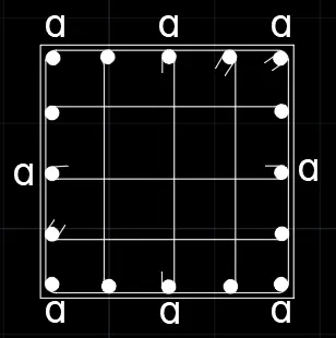
(c)P3
STEP 1:
- Open the AutoCAD software and click start Drawing tab.
- Enter UNITS in command box.
- Select ENGINEERING in TYPE, 0’0” in PRECISION and INCHES in UNITS TO SCALE INSERTED Press OK.
- Switch on ORTHOMODE.
- Enter REC in command box
- Enter 24” as length
- Enter 24” as width
- Enter 0.5” as offset distance
- Select the rectangle and create offset
- Enter L in command box
- Enter 5.5 as first point
- Connect it to the end point
- Enter O in command box
- Enter 5.5 as offset distance
- Select the line and create 2 offsets
- Enter L in command box
- Enter 5.5 as first point
- Connect it to the end point
- Enter O in command box
- Enter 5.5 as offset distance
- Select the line and create 2 offsets
- Enter C in command box
- Enter 0.62” as radius
- Enter CO in command box
- Copy the circle and place at appropriate position
- Enter 1” as fillet radius
- Select the circle and line to create curve shape
- Switch off ORTHOMODE
- Click on the circle and create lines
- Select MULTILINE TEXT in RIBBON.
- Click SYMBOL and select others.
- Click ARIAL as font and select Latin Small Letter Alpha (U+0251).
- Select it and press ENTER.
- Enter CO in command box and copy it in the required place.
STEP 2:
- Enter REC in command box
- Enter 4’6” as length
- Enter 4’6” as width
- Enter L in command box
- Enter 6” as first point
- Enter L in command box
- Enter 6” as first point
- Enter 1’6” as next point
- Enter 1’ as next point
- Enter O in command box
- Enter 1’3” as offset distance
- Enter O in command box
- Enter 1’6” as offset distance
- Enter DIMS in command box
- Click MODIFY. In SYMBOLS and ARROWS, Enter ARROW SIZE as 1’.
- In TEXT, Enter TEXT HEIGHT as 1’.
- In PRIMARY UNITS, Click ENGINEERING in UNIT FORMAT, 0’0” in PRECISION.
- In LINES, Enter 1’ as EXTEND BEYOND LINES and 1’ as OFFSET FROM ORIGIN. Click OK.
- Click SET CURRENT. Click CLOSE.
- Enter DIML in command box
- Click the points to get dimensions
- Enter DT in command box
- Enter 1’ as text height
- Enter the text
- Use TEXTEDIT AND CO for editing and copying the text
- Click the layers and place it on the dimensions, objects and text
- Save the drawing and rename it as AUTOCAD CHALLENGE 6.
RESULT:
The Column details is created by lines using AutoCAD. The step-by-step procedure for creating column details is also explained. The Dimension is also entered in the diagram.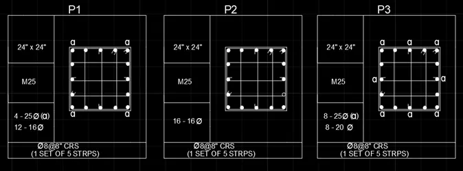
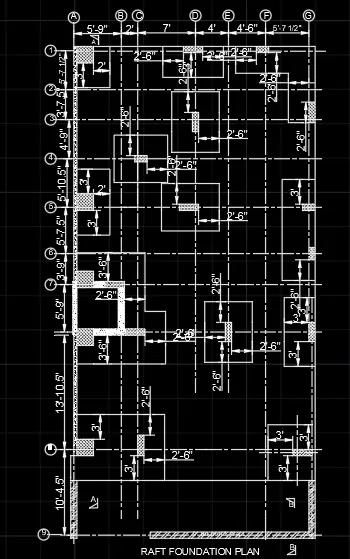
Q 5. Draw the Raft Layout as shown in the Figure. Assume the column size as per your knowledge. You can take the sizes as: 24”x24”, 9” x 24”, 9” x 18”, and 9’ x 24”. You can import the raft_foundation.pdf to ensure the missing dimensions.
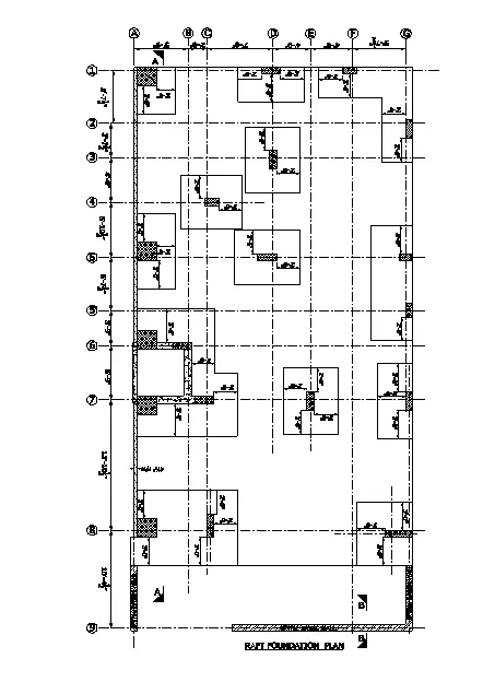
5)ans: RAFT LAYOUT
AIM: To create the raft layout using AutoCAD.
INTRODUCTION: The raft layout using AutoCAD is created by Lines and Circles. The procedure and result should be written after creating the raft layout.
PROCEDURE:
STEP 1:
- Open the AutoCAD software and click start Drawing tab.
- Enter UNITS in command box.
- Select ENGINEERING in TYPE, 0’0” in PRECISION and INCHES in UNITS TO SCALE INSERTED CONTENT. Press OK.
- Switch on ORTHOMODE.
- Enter L in command box
- Enter 0,0 as first point
- Enter 10’-4 ½”, 13’-10 ½”, 5’9”, 3’9”, 5’-7 ½”, 5’-10 ½”, 4’9”, 3’-7 ½” and 5’-7 ½”
- Enter 5’9”, 2’, 7’, 4’, 4’6” and 5’-7 ½”
- Close the rectangle tracking the lines
STEP 2:
- Enter L in command box
- Enter 6’7.5” as first point
- Extend the line to other side
- Enter 9” as offset
- Enter 3’ as next point
- Enter 9” as next point
- Enter 24” as next point
- Enter 24” as next point
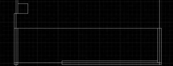
STEP 3:
- Enter O in command box
- Enter 10’-4 ½” as offset distance
- Extend the line
- Create the line tracking square
- Enter 9” as length
- Enter 28” as width
- Enter line at 2’6” after the rectangle
- Enter 2’6” above and close the line
- Create a rectangle
- Enter 18” as length
- Enter 9” as width
- Enter 3’ after rectangle
- Enter 6’9” above and close the line
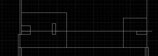
STEP 4:
- Enter O in command box
- Enter 13’-10 ½” as offset distance
- Enter L in command box
- Enter 4.5” above line
- Enter 23.5” below line
- Close the rectangle
- Enter 3.6” as next point
- Draw the line and enter 18” as length and 9” as width
- Enter 2’6” after the rectangle
- Enter 2’6” after the rectangle
- Enter 4.5” either side
- Enter 4.5” either side of 5’9”
- Again draw the square
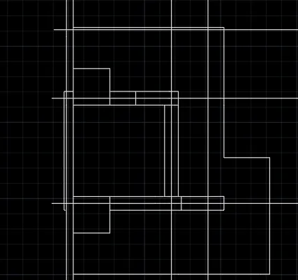
STEP 5:
- Enter L in command box
- Enter 4’ as offset distance
- Enter 4.5” on either side
- Enter 2’6” on upper side, down side, left side and right side
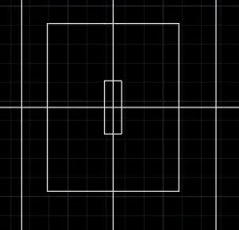
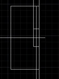
STEP 6:
- Enter O in command box
- Enter 5’-7 ½” as offset distance
- Enter 9” as length and 18” as width
- Enter 3’ on either sides
STEP 7:
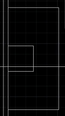
- Enter O in command box
- Enter 5’-7 ½” as offset distance
- Enter 4.5” below line
- Enter 24” and connect it
- Enter 19.5” above
- Enter 3’ below it
- Enter 2’ at right side
- Enter 3’ above it
STEP 8:
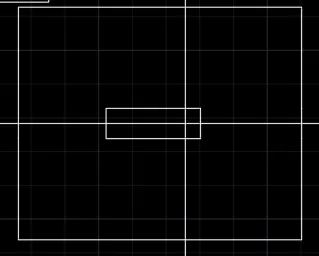
- Enter O in command box
- Enter 7’ as offset distance
- Enter 4.5” at right side and 23.5” at left side
- Enter 2’6” at right side and upper side
STEP 9:
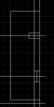
- Enter L in command box
- Enter 4.5” on either side of 5’7 ½” line
- Enter 9” on either side of 3’9” line
- Enter 2’6” below it
- Enter 2’6” after the rectangle
- Enter 3’ above it
STEP 10:
- Enter L in command box
- Enter 4.5” at right side
- Enter 9” at top side
- Enter 23.5” at left side and close it
- Enter 2’6” at right side, left side, upper side and lower side
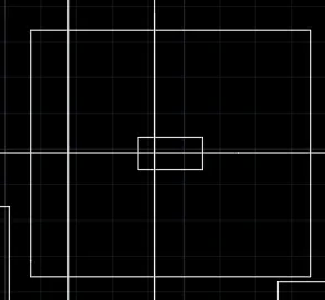
STEP 11:
- Enter L in command box
- Enter 4.5” on either side of 7’ line
- Enter 2’6” on all sides
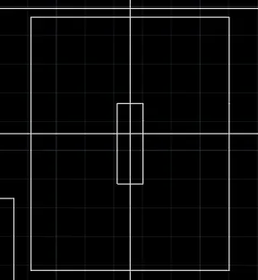
STEP 12:
- Enter L in command box
- Enter 4.5” above 5’ 7 ½” above it
- Enter 19.5” below
- Enter 3’ below rectangle
- Enter 2’ after square
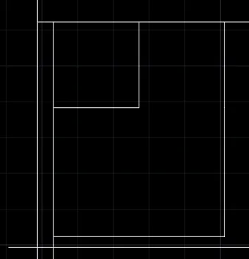
STEP 13:
- Enter L in command box
- Enter 28” as length and 9” as width
- Place it tracking previous rectangle
- Enter 2’6” on either side
- Enter 3’ at lower side
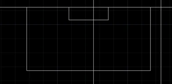
STEP 14:
- Enter L in command box
- Enter 4.5” at right side and 13.5” at left side
- Enter 2’6” at left side and lower side
- Enter 2’6” after 5’7 ½” line
- Enter 4.5” above 3’7 ½” line
- Enter 19.5” below it
- Enter 2’6” below it
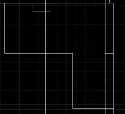
STEP 15:
- Enter H in command box
- Click ANSI37 with 1” spacing
- Click AR-CONCRETE with 0.05” spacing
- Click ANSI32 with 1” spacing
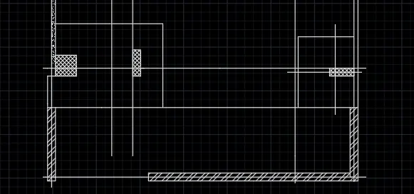
STEP 16:
- Click LAYER PROPERTIES
- Click NEW LAYER
- Enter RAFT in NAME
- Select ACAD_ISO08W100 as LINETYPE
STEP 17:
- Enter DIMS in command box
- Click MODIFY. In SYMBOLS and ARROWS, Enter ARROW SIZE as 11”.
- In TEXT, Enter TEXT HEIGHT as 11”.
- In PRIMARY UNITS, Click DECIMAL in UNIT FORMAT, 0 in PRECISION.
- In LINES, Enter 1” as EXTEND BEYOND LINES and 1” as OFFSET FROM ORIGIN. Click OK.
- Click SET CURRENT. Click CLOSE.
- Click DIMENSIONS AND TEXT dropdown in LAYER.
- Enter DIML in command box and drag the dimensions.
- Enter DT in command box. Enter 11” as TEXT HEIGHT and 0 as TEXT ROTATION ANGE.
- Enter TEXT.
- Enter CO in command box. Copy the text and place it in another location.
- Enter TEXTEDIT in command box. Using this, editing in text can be done.
- Click the layers to give their properties in diagrams
RESULT:
The Raft layout is created by lines using AutoCAD. The step-by-step procedure for creating Raft layout is also explained. The Dimension is also entered in the diagram.