Creating a Wardrobe detailed drawing, Floor Plan, Kitchen Layout and Column Detail using AutoCad
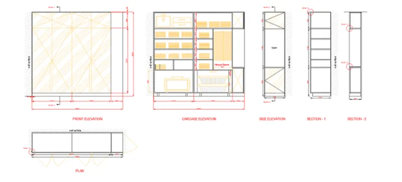
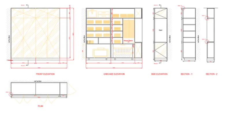
- Sketch the elevation and details of a wardrobe as given in the picture below. After drawing, you require to give the dimensions and text with the utilize of layers. Utilize correct text styles and dimension procedures to document it. Also, suppose dimensions, wherever required.
Note: All dimensions are in mm.
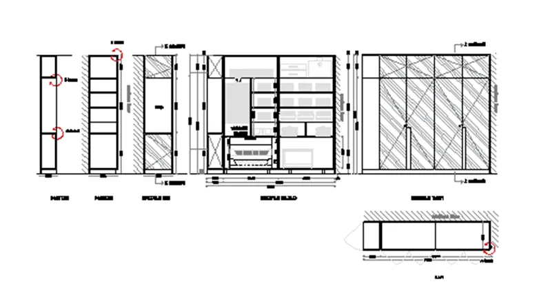
AIM- To sketch the elevation and details of a wardrobe and to give the dimensions and text with the utilize of layers.
INTRODUCTION- A wardrobe or armoire or admiral is a standing closet utilized for storing clothes. The earliest wardrobe was a chest, and it was not until some degree of luxury was attained in regal palaces and the castles of powerful nobles that separate accommodation was given for the apparel of the great.
PROCEDURE-
Step-1 Setting up units
- Give the command units then choose the decimal unit , precision > 0, insertion scale > MM
Step-2 Making the front elevation
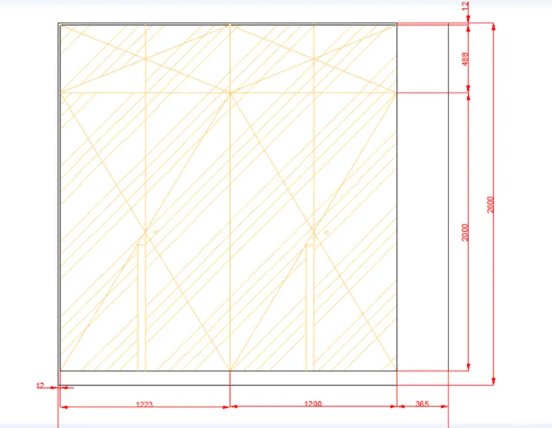
- By utilizing line command generate the horizontal line of 2800mm and vertical line of 2600 then horizontal 2800 then close the line at initial point the rectangle will generated.
- Now provide the offset command then provide the distance of 12mm then do offset at left side and upper line.
- Now once more from offset command do offset of bottom line at distance 100 and again do offset of that line distance 2000.
- Once more provide the offset command and do offset of vertical line of 1200distance from the right hand side.
- Provide the line command and meet the edges as given in pic.
- Generate the handle by utilizing the circle command.
- Provide the hatch command and hatch the elevation.
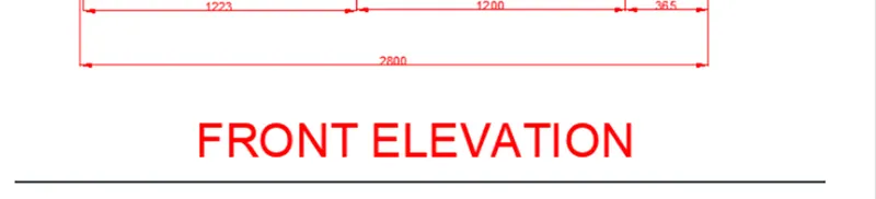
- Dimensions also inserted by utilizing the DIM command.
- The elevation will be generated.
Step-3 Making the plan
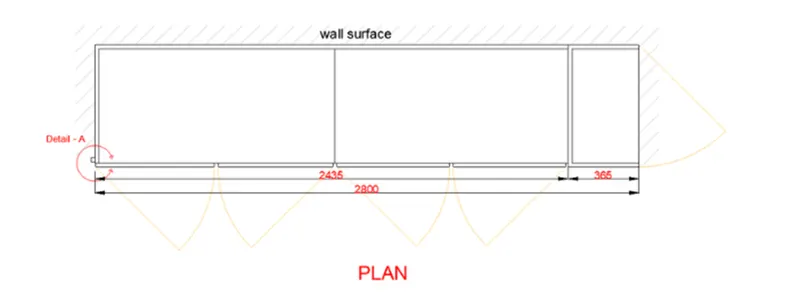
In the command prompt type rectangle> 630 x2800 In the command prompt type leader to provide the annotations
Step-4 Making the carcase elevation
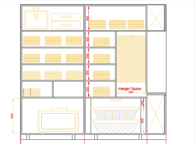
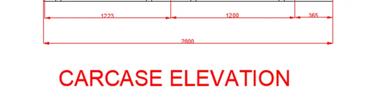
- Copy the earlier shown pic and paste beside and ears the hatch and extra not needed lines.
- Now by utilizing the offset command do offsets to make cabinetries and by utilizing line command the cabinets are generated.
Step-5 Making the side elevation and the sections
- By utilizing line command project the lines from the carcase elevation then generate the side elevation with provided width of 630 the do offsets we needed.
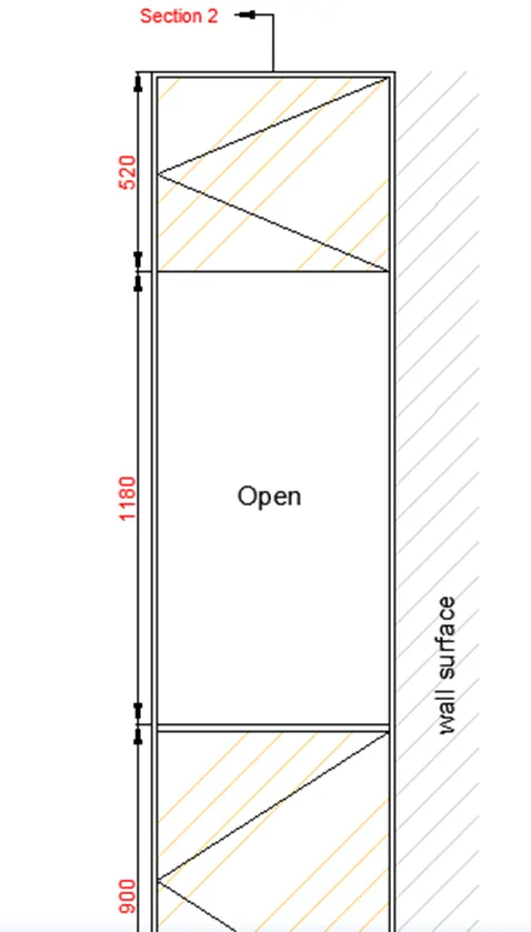
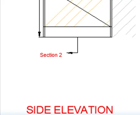
- And copy the side elevation paste beside then delete not needed carbonated then generated the carbonated at the section.
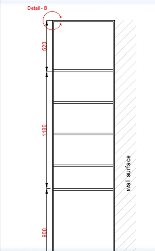
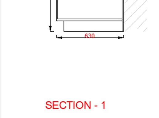
- Now the same length and interchange the width and generate the section 2 and utilized offset command and generated the cabinets.
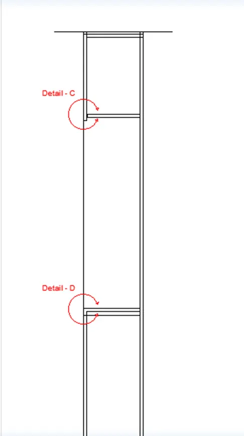
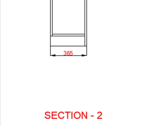
RESULT- The elevation, plan, carcase elevation, side elevation and sections are generated by utilizing the AutoCAD.
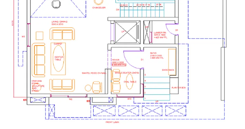
Q2. Sketch the floor plan as given in the picture. Utilize the correct drafting tools to draw the plan. Do not hatch or sketch the furniture. You require sketching the floor plan with the following: Note: You can also import the Floor_Plan.pdf into your current sketching and start working on the project. You require to scale the imported pdf file utilizing reference option. All dimensions are in mm.
- Walls (Exterior and Interior)
Wall Thickness: Exterior Wall- 230mm, Interior Wall: 150 mm (Wherever needed)
- Doors and Windows: A assume the size of the doors and window.
- Stairs: Tread-300mm, Riser-150mm
- Insert Text wherever required
- Insert the dimensions utilizing accurate dimension methods
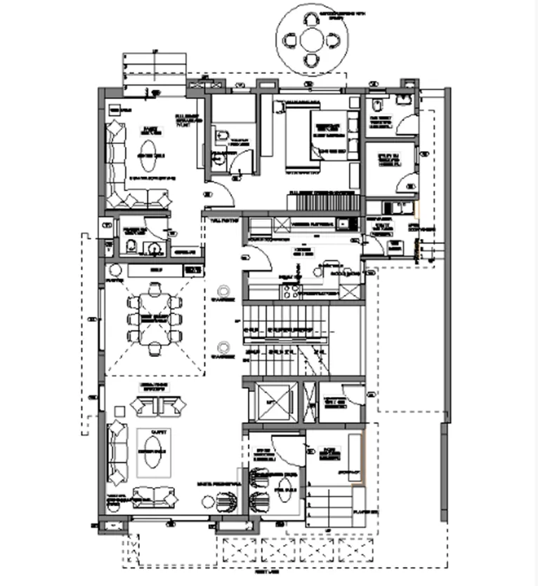
AIM: To sketch the floor plan as given in the picture. Utilizing the accurate drafting tools to sketch the plan. Do not hatch or draw the furniture.
INTRODUCTION: In architecture and building engineering, a floor plan is a technical drawing to scale, showing a view from above, of the relationships between rooms, spaces, traffic patterns, and other physical features at one level of a structure.
PROCEDURE:
Step-1 Setting up units
- Provide the command units then choose the decimal unit , precision > 0.0, insertion scale > MM
Step-2
- In command line provide the x line and make horizontal and vertical line.
- From the bottom left corner stared the sketching.
- Now provide the offset do offset from vertical line of distance 230mm and once more do offset from earlier line of distance 5310(Living & Dining room length) and offset wall thickness once more offset of foyer width of 2000 than offset wall thickness and offset the patio 2150 than offset the wall thickness.
- Provide the trim command and trim the not needed lines.
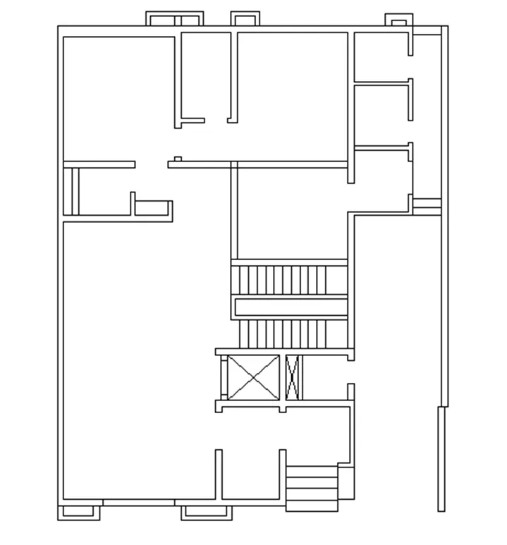
- In command prompt provide the offset command do offset of horizontal line at 230mm (wall thickness) and offset the earlier line at distance of 3220mm and offset the wall thickness and once more do offset the width of foyer at 1600 and offset the wall thickness.
- Now once more provide the command of offset and do offset of distance 9710 from the internal line of the living room.
- Do offset of earlier line at distance of 1650 vertical and 1800 horizontal offset and do offset wall thickness also.
- By utilizing trim command trim the not needed lines.
- Then the pic will seem.
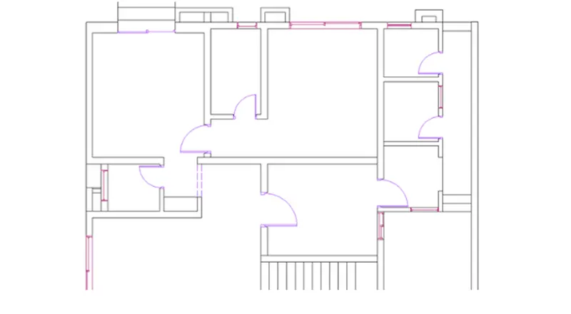
Step-3 Making the doors and windows
- By using offset command, line command and arc command we will sketch the door and windows.
- By command prompt provide line command sketch the line of the length as the door width then make door frame and draw the arc as give in pic.
- Now come to windows provide the command offset sketch the windows and trim the not needed line.
- And also as we drawn windows sketch the ventilators at needed position.
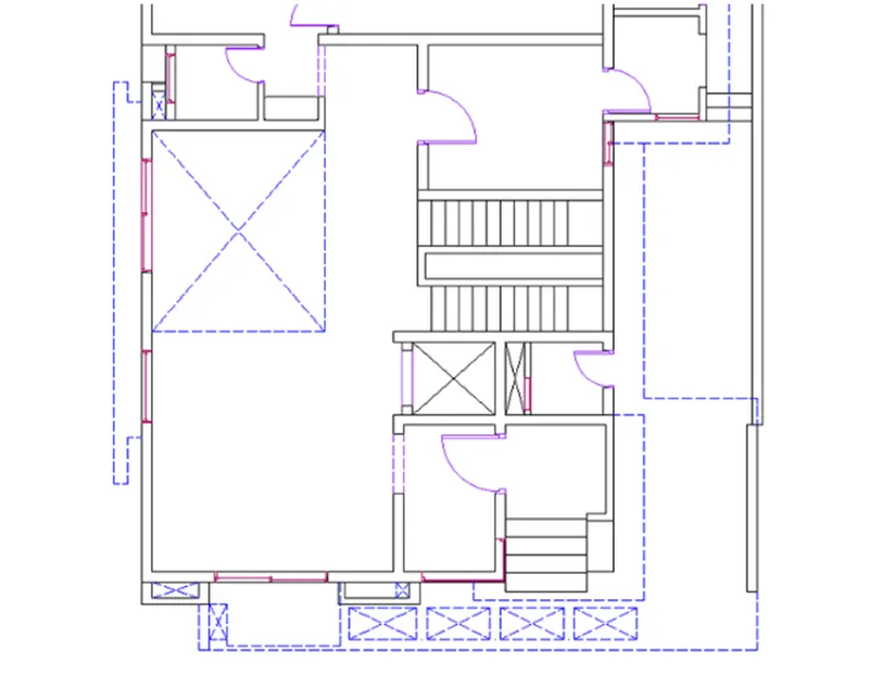
Step-4 Making the shaded lines or dash lines
- Go to the layers panel then choose the Linotype manager then load the line types then choose the dash lines click on load.
- Then choose the dash line type then click on ok.
- The dash line will be generate lines generated and then if need choose the line and go to the properties interchange the scale then the line visuals.
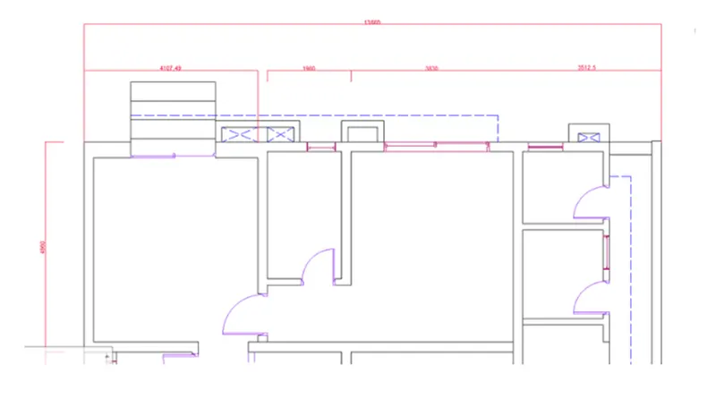
Step-5 Making the dimensioning or showing the dimension
- In the command prompt provide the DIMS command then interchange the settings as we need then provide command DIS the give dementing.
- If we want to interchange the dimensions from linear to angular we have to go to the annotation panel the interchange the type.
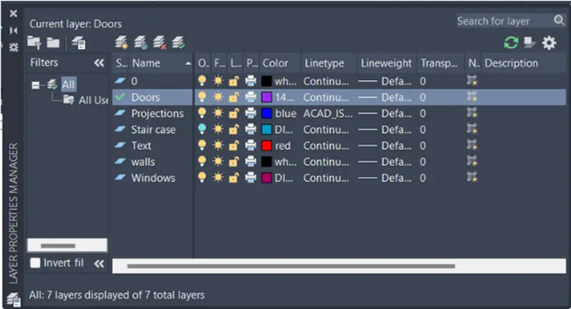
Step-6 Generating the layers
- In the command prompt provide the command layers.
- Then generated the no.of a layer does need.
- Specify layers remain the layers.
- Try to the objects.
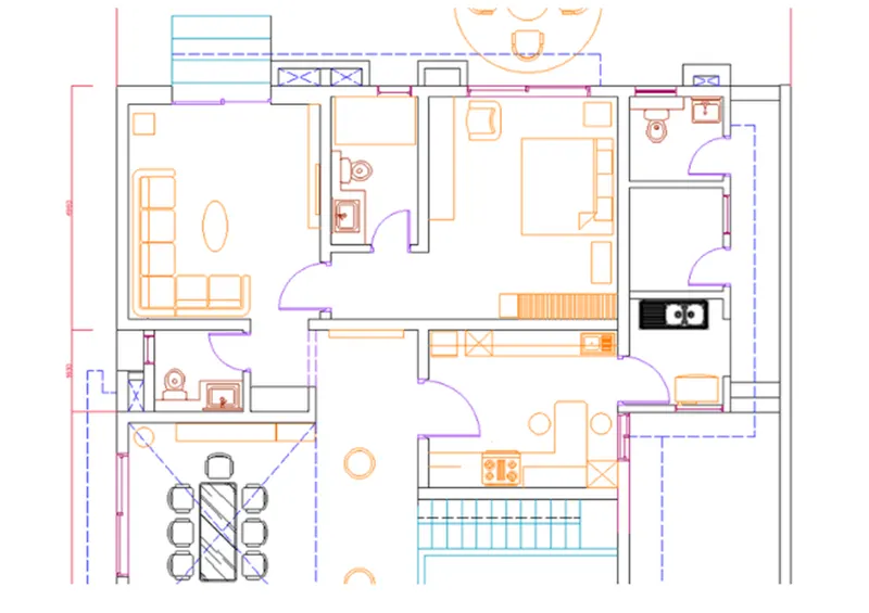
Step-7 Generating the furniture
- In the command prompt provide the command design center.
- Insert the furniture as needed.
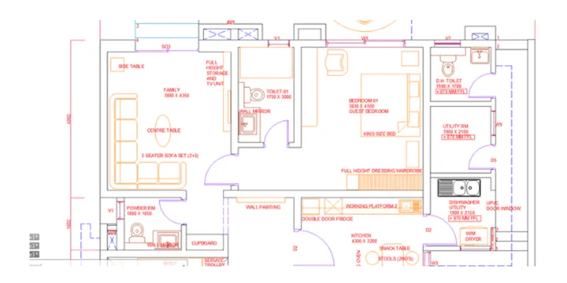
Step-8 Generating the text
- In the command prompt provide the multi text command.
- Specify the text and also dimensions by text.
Step-9 Generating the OUTDOOR SEATING WITH CANOPY
- Incoming prompt provide the command circle and generate the circle.
- And by utilizing the offset command generate the OUTDOOR SEATING WITH CANOPY.
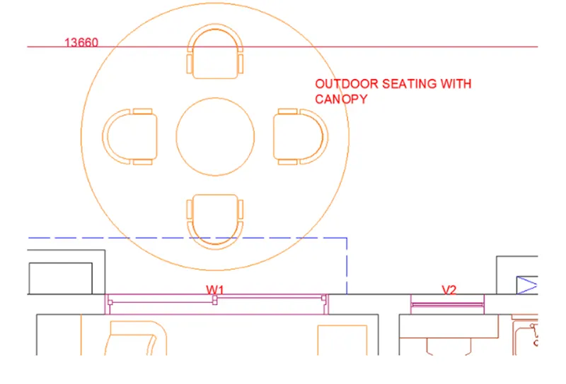
RESULT:
The floor plan is successfully sketched by utilizing AUTOCAD SOFTWARE
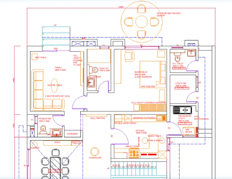
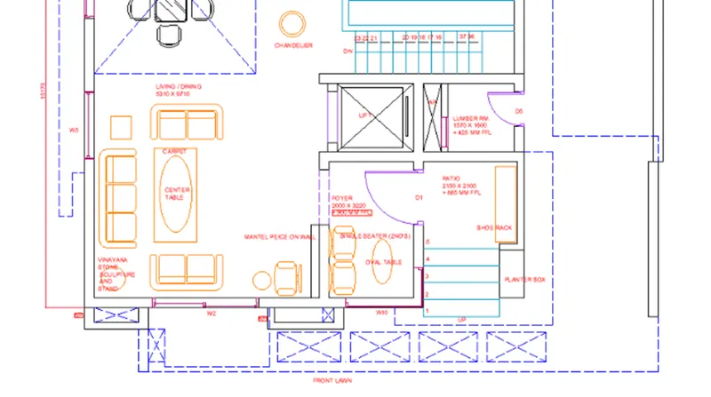
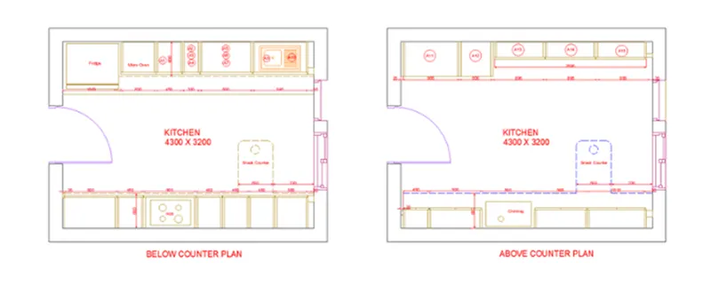
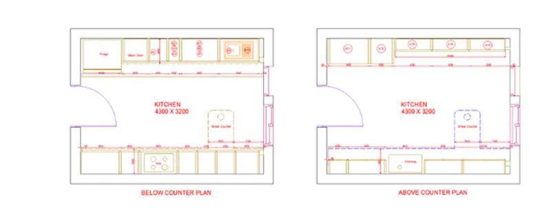
Q3. Generate the Kitchen Layout as given in the picture below. Also, utilize accurate dimension methods to dimension the kitchen layout. Also, insert text wherever needed. All dimensions are in mm.
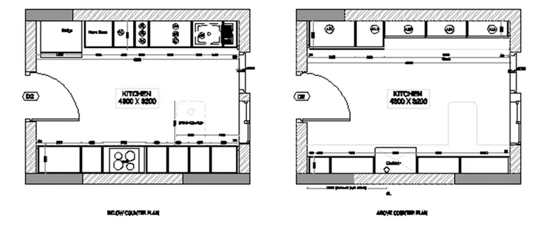
AIM: To sketch the kitchen layout with accurate dimension methods in the AutoCAD in detail.
INTRODUCTION:
- Kitchen layout is the most prime part of designing your perfect kitchen. It's the layout that will decide how you cook, how you eat and how you socialize.
- So whether you're totally remodeling the kitchen, buying new appliances or easily interchanging the cabinets, we've included the top five prime common kitchen layouts to help admires you.
Command utilized:
- Limits command
- Line command
- Offset command
- Hatch command
- Dim linear command
- Dim style command
- Units command Extend command
- Fillet command
- Trim command
- Join command
- Line weight command
- Line type command
- Object snap command
PROCEDURE:
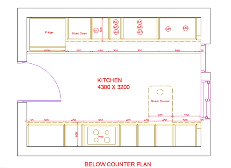
Step-1 Below counter plan
- First we have to sketch the line horizontally with the length of 4300mm.
- Next sketch another line from the earlier line with the length of 3200mm vertically upwards. Next once more we sketch the line from earlier line with the length of 4300 mm horizontally backwards at the top.
- Next we have to meet the first line and the last line which we have sketched earlier.
- Next offset the four sides with the offset of 20mm outside.
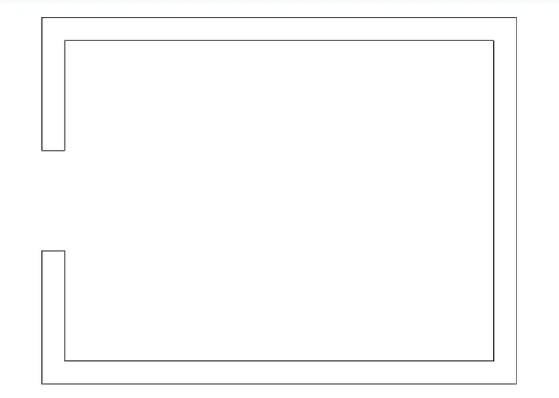
- Next we have to offset the line inside with the offset command with the length of 600mm, including the fridge.
- Afterwards we sketch the fridge individually with other dimensions in the kitchen layout.
- Next we require drawing the line opposite side to make the parts of kitchen.
- Next divide the seven parts downside with different dimensions compared to the upper side portion.
- Next leave the space left and right corners with the length of 35mm at the top and bottom.
- Next put the dimensions for the each part in the picture.
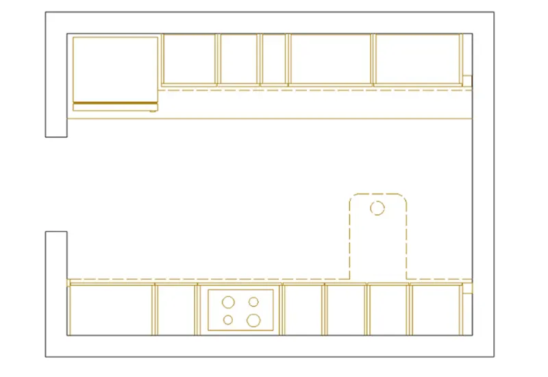
- Next specify the door as D2.
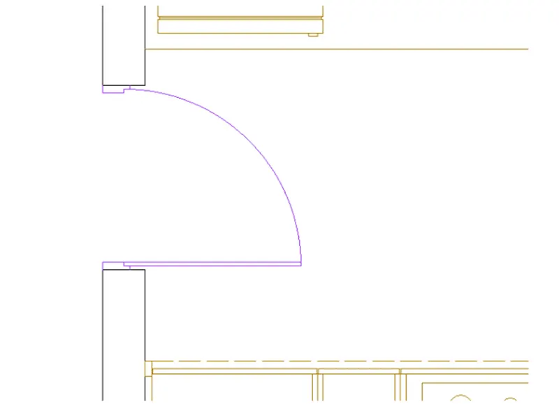
- Next we have utilized the single text command and specify the parts where ever it needs with single text command.
- And put the dimensions for the each part in the picture.
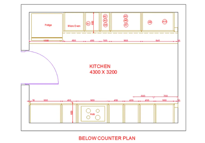
- Next sketch the snack counter with the length of 600mm and width of 900mm, and sketch the circles to make the hub in the mid at the bottom of the kitchen.
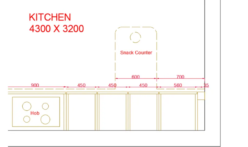
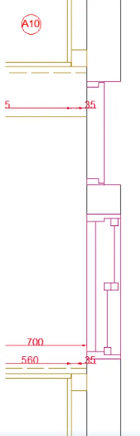
- And make the windows utilizing the line command and trim command, which is given in the below picture.
Step-2 Above counter plan
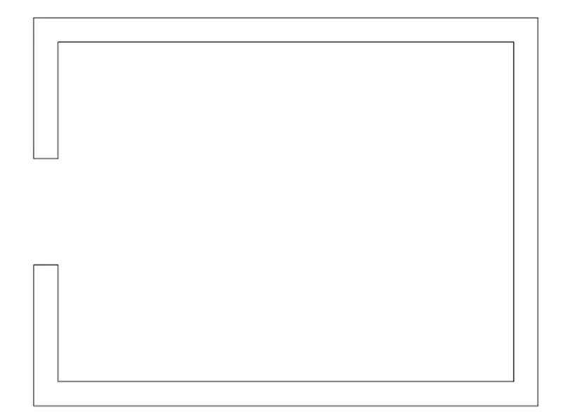
- First we have to sketch the line horizontally with the length of 4300mm.
- Next sketch another line from the earlier line with the length of 3200mm vertically upwards.
- Next once more we sketch the line from earlier line with the length of 4300 mm horizontally backwards at the top.
- Next we have to meet the first line and the last line which we have sketched earlier.
- Next offset the four sides with the offset of 20mm outside.
- Next we have to offset the line inside with the offset command with the length of 350mm, and once more we do offset of 600mm in the same side.
- And leave the space for both side corners with the length of 35mm.
- And do offset for the inside parts with the length of 10mm for all sides of the all parts in the kitchen layout.
- Next we have to do the offset of 350mm at the bottom portion of the kitchen.
- And the bottom portion into five parts, and once more offset them with the length of 10mm.
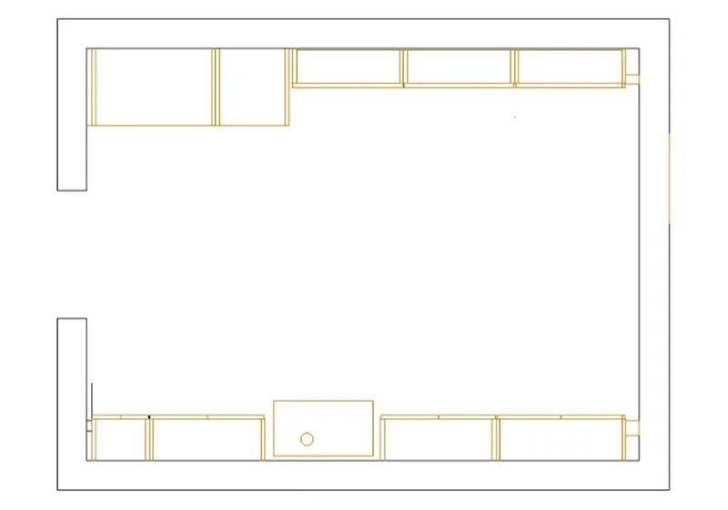
- Next we have to utilize the different hatch styles to hatch the walls in the kitchen layout.
- Next we have to sketch the doors utilizing the line command, circle command and trim command.
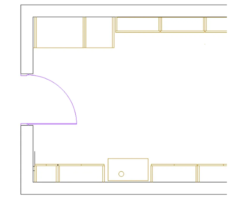
- Next we have to sketch the windows utilizing the line command and trim command.
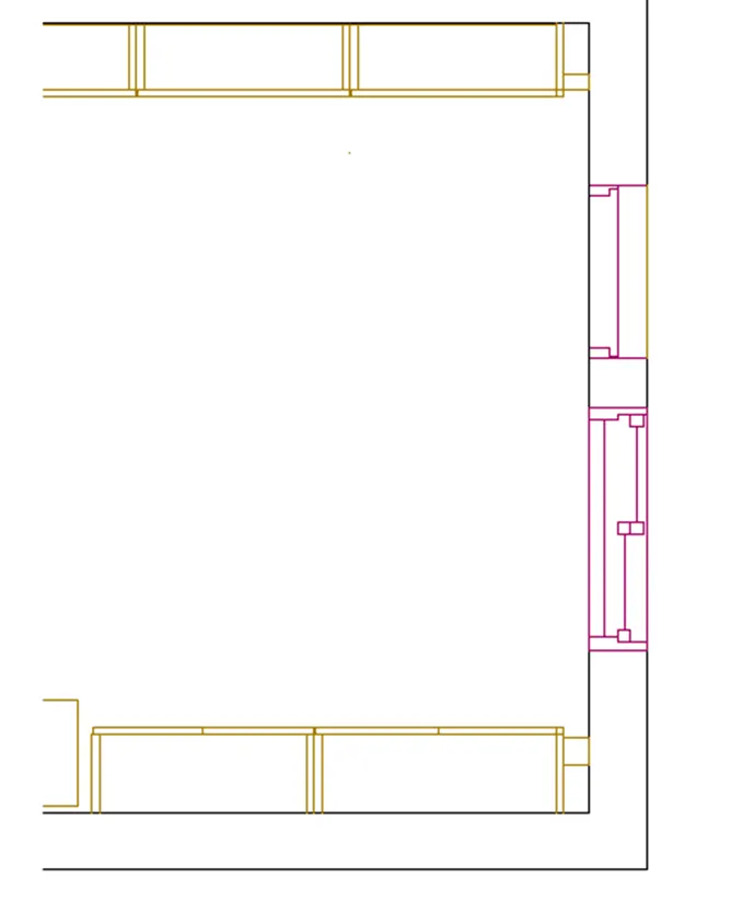
- And next we have to utilize the dim linear command to put the dimensions where ever they are needed.
- Next utilize the single text command to specify the kitchen parts in the kitchen layout which we have sketched in the below picture.
- Ultimately we sketch the snack counter with the length of 600mm and width of 900mm.
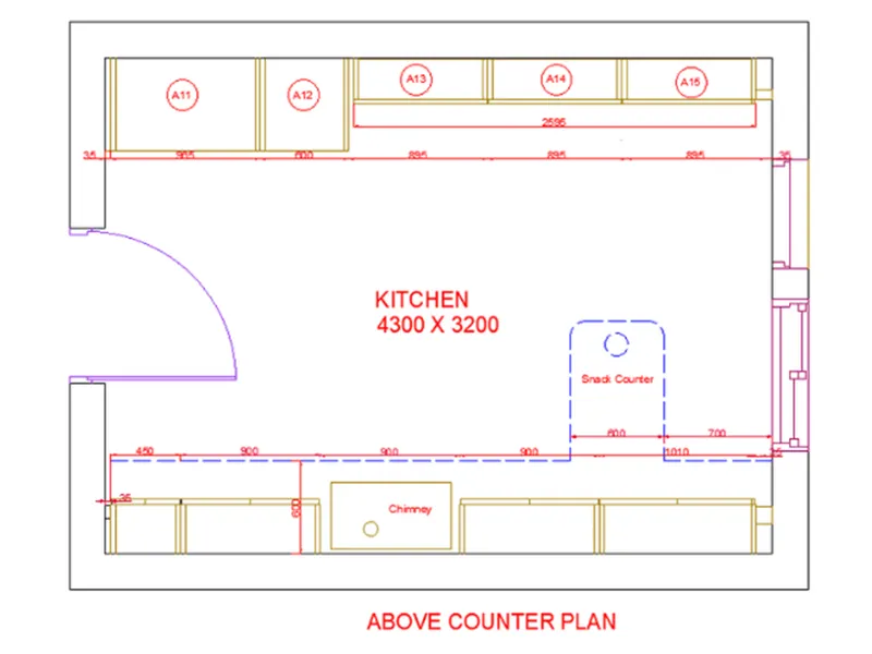
RESULT: The kitchen layout is sketched successfully in the AutoCAD with accurate dimension methods in detail.
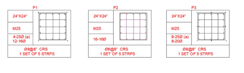
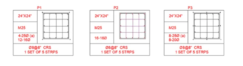
Q4. Draw the column details as shown in Picture. Insert dimensions and text in the picture. Refer to the bar sizes from the schedule. 8mm ---- 0.31 Inches 25mm--- 1 inch 16mm—0.62 inches
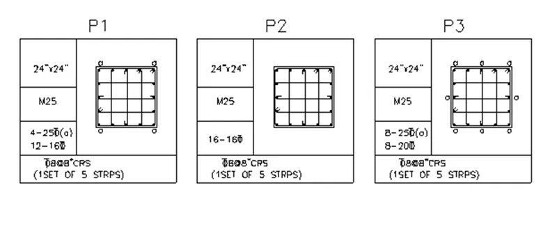
AIM: To sketch the column detailed with accurate dimensions in the AutoCAD in detail.
INTRODUCTION:
- Columns are the vertical members of a building structure that utilize to help the slabs and beams
- It serves as a backbone of the structures so we can gain the height that we need in a provided project.
- A column comes with different types that ranges in shapes and sizes depending on the loads and conditions of a structure.
- Design of columns had a different approach according to each type, whether it is a plain concrete column, a reinforced concrete column, a steel column and a composite one. Although the design differs similarly. Columns are differentiated and designed similar to its length, the short and the long column.
Command utilized:
- Limits command
- Single text command Line command
- Dim linear command
- Trim command
- Circle command
- Object snap command
- DONUT command
- Divide command
- Offset command
- Units command
- Dim style command
- Extend command
- Mirror command
PROCEDURE:
Step-1 P1
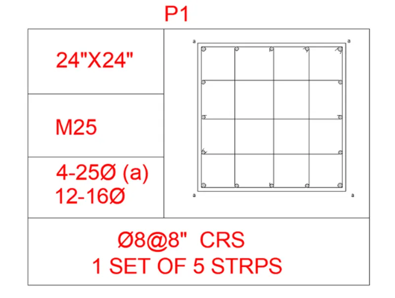
- First we sketch the column with provided details as given in below picture.
- First we sketch the line with the length of 24" horizontally.
- Next we sketch the 24" line vertically, and then once more sketch the line with the length of 24".
- Ultimately we meet the first line and last line.
- Then after we do offset of 0.6", and do the offset to inside of rectangle we sketched earlier.

- Now we take the circle diameter as 16mm and 20mm individually.
- Now utilize the divide command and provide the 4 segments inside the rectangle.
- Now put the circle in the each segment.
- After placing the 20mm dia circles at the 4 corners in the column.
- Mirror the one side fixed circles to other side.
- Next put the 16mm rods in the remaining places.
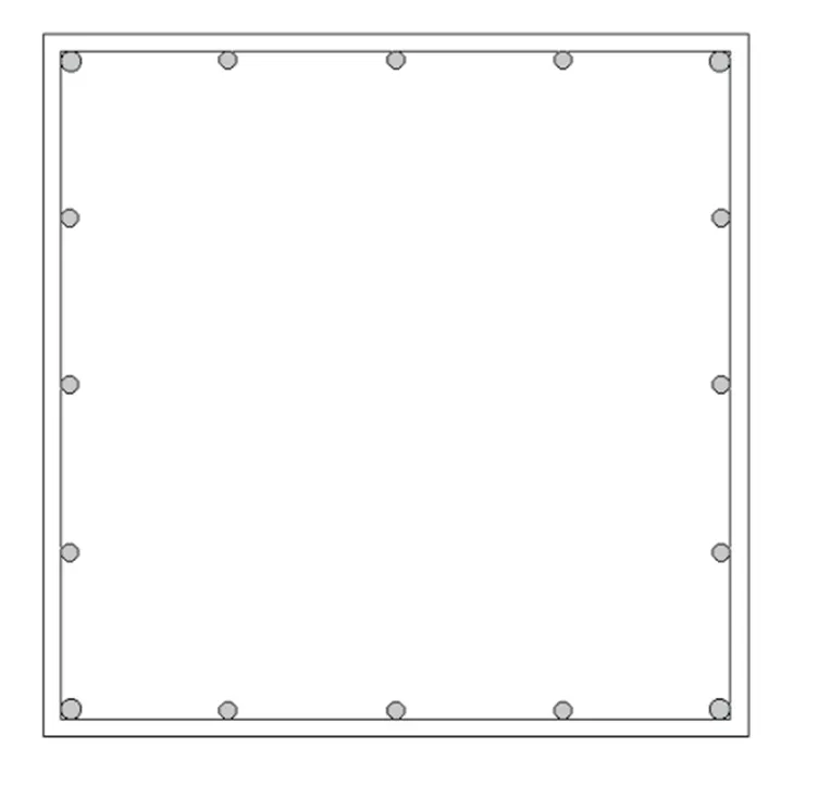
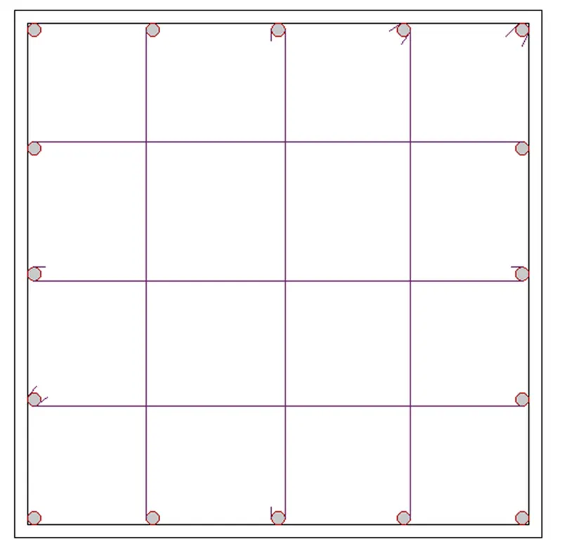
- And put the 5 stirrups in the column where they are needed to put in fix position.
- And Bend the corner of stirrups to the 45 degrees, as given in below picture.
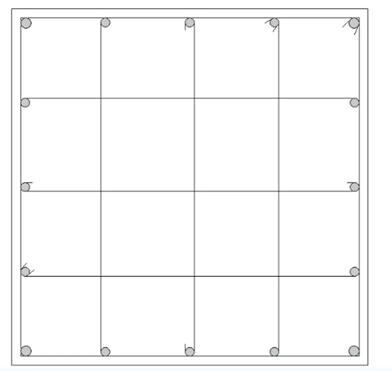
- Ultimately we have to sketch the table utilizing the line command as given in below table.
- Next we require entering the details of columns with Single text.
- And next put the column picture in the table we generated, as given below.
Step-2 P2
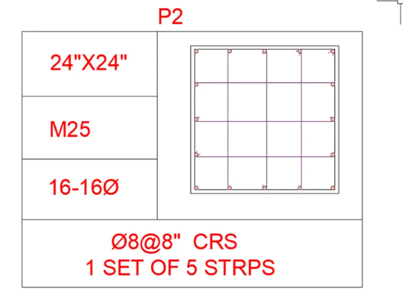
- We sketch the column with provided details as given in below picture.
- First we sketch the line with the length of 24" horizontally.
- Next we sketch the 24" line vertically, and then once more sketch the line with the length of 24".
- Ultimately we meet the first line and last line.
- Then after we do offset of 0.6", and do the offset to inside of rectangle we sketched earlier.

- Next sketch a circle beside of the earlier picture; we take the circle diameter as 16mm for 16 bars.
- Now utilize the divide command and provide the 4 segments inside the column.
- Now put the circle in the each segment.
- After putting the circles on one side, we utilize the mirror command.
- Mirror the one side fixed circles to other side.
- And put the 5 stirrups in the column where they are needed to put in certain position.
- And bend the corner of stirrups to the 45 degrees, as given in below picture.
- Ultimately we have to sketch the table utilizing the line command as given in below table.
- Next we require entering the details of columns with Single text.
- And next place the column picture in the table we made, as given below.
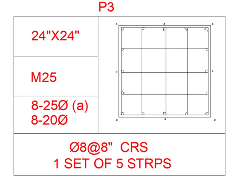
Step-3 P3
- We sketch the column with given details as given in below picture. • First we sketch the line with the length of 24" horizontally.
- Next we sketch the 24" line vertically, and then once more sketch the line with the length of 24".
- Ultimately we meet the first line and last line.
- Then after we do offset of 0.6", and do the offset to inside of rectangle we sketched earlier.
- Now we put the circle diameter as 25mm and 20mm individually.
- Now utilize the divide command and provide the 4 segments inside the column.
- Now put the circle in the each segment.
- After placing the 20mm dia circles at the 4 corners in the column.
- And we require to put the 25mm bars in the mid of the four sides in the column.
- Next put the 20mm rods in the remaining places.
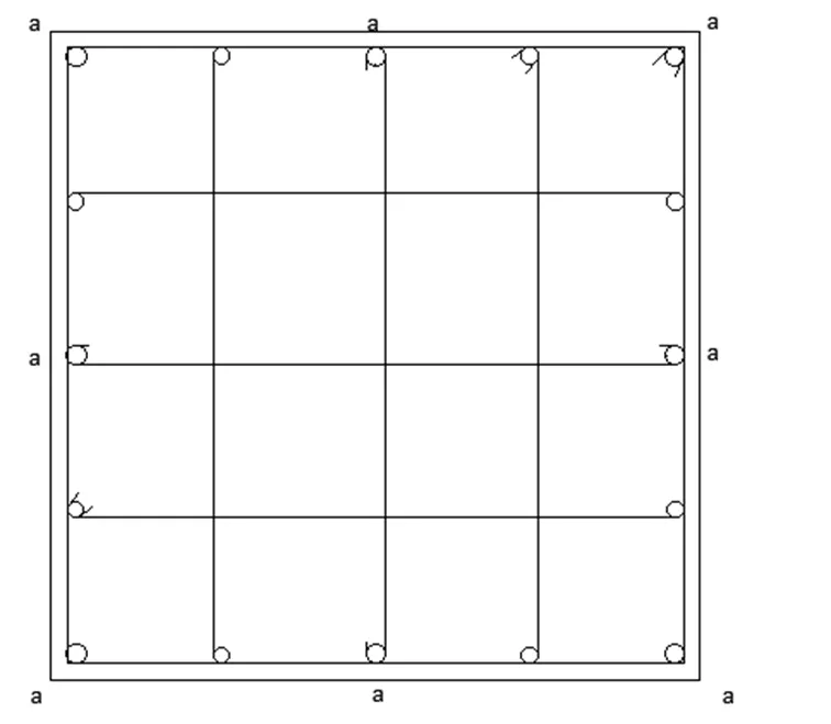
- And put the 5 stirrups in the column where they are needed to put in fix position.
- And bend the corner of stirrups to the 45 degrees, as given in below picture.
- Finally we have to sketch the table utilizing the line command as given in below table.
- Next we require entering the details of columns with Single text.
- And next put the column picture in the table we generated, as given below.
RESULT: The column details with accurate dimensions are sketched successfully in the AutoCAD.
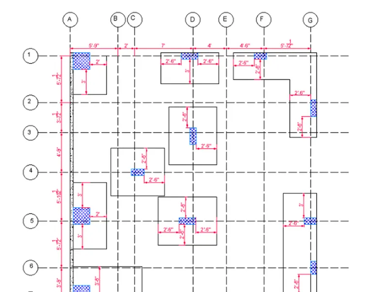
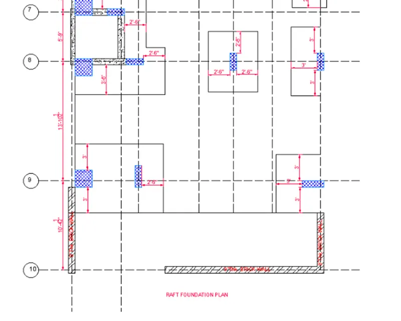
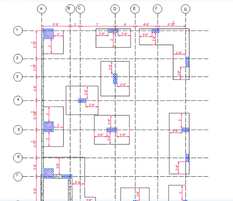
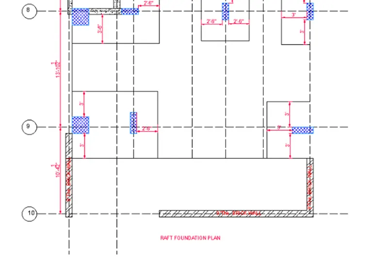
Q 5. Sketch the Raft Layout as given in the picture. Suppose the column size as per your knowledge. You can take the sizes as: 24”x24”, 9” x 24”, 9” x 18”, and 9’ x 24”. You can import the raft_foundation.pdf to make sure the absent dimensions.
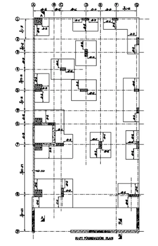
AIM: To sketch the raft foundation layout in the AutoCAD with accurate dimensions in detail.
INTRODUCTION:
- Raft foundation is really a thick concrete slab resting on a large area of soil reinforced with steel, helping columns or walls and place loads from the structure to the soil.
- Generally, mat foundation is spread over the whole area of the structure it is helping.
- Raft foundation is usually utilized to help structures like residential or commercial buildings where soil condition is poor, storage tanks, silos, foundations for large industrial equipment.
Command utilized:
- Limits command
- Xline-V
- Zoom command
- Offset command
- Hatch command
- Dim linear command
- Units command
- Extend command
- Fillet command
- Trim command
- Join command
- Line weight command
- Line type command
- Object snap command
PROCEDURE:
Step-1
- First we have to open the AutoCAD and set the limits utilizing the limits command.
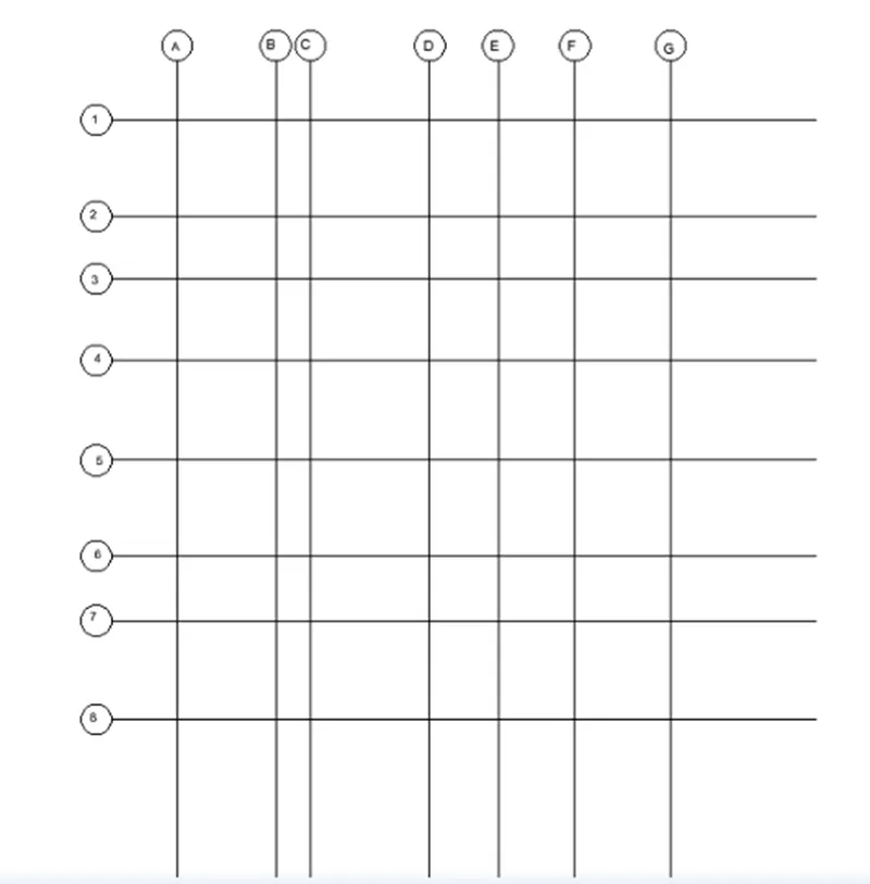
- Next we have to choose the Xline command and set to horizontal and vertical. And create that xlines as the grid lines for the sketching of the raft layout.
- Offset the vertical lines up to seven lines.
- And offset the horizontal lines up to nine lines.
- And name the horizontal lines with numbers.
- And name the vertical grid lines with the alphabets.
- And also sketch the walls where they are needed in the sketching, utilizing the line command and offset command.
Step-2
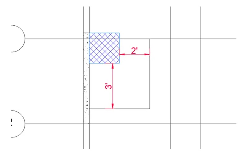
- Next we have to sketch the column and footing with the needed dimensions.
- We take the column length is 24" and the width is 24".
- And the footing length is 2'-24" and width is 3'-24".
Step-3
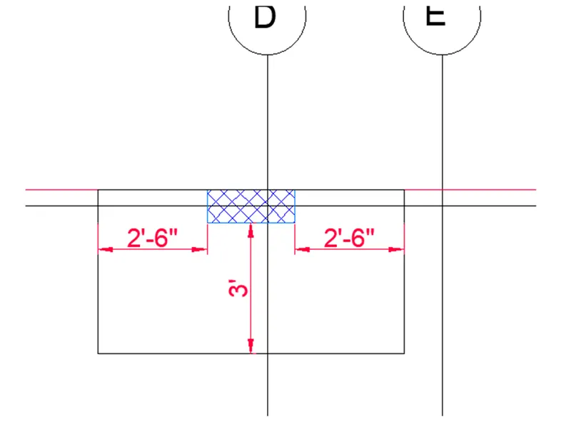
- Next we have to sketch the column and footing with the needed dimensions.
- We take the column length is 9" and the width is 24".
- And the footing length is '5-24" and width is 3'-24".
Step-4
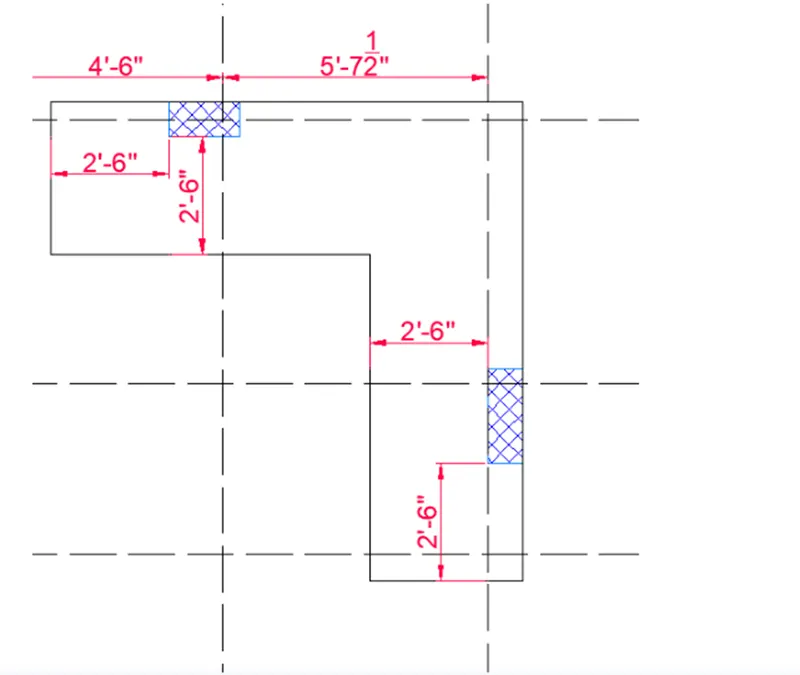
- Next we have to sketch the column and footing with the needed dimensions.
- We take the column length is 9" and the width is 24".
- We take the column length is 9" and the width is 18".
- Next we do the offset of 2'-6" horizontally and vertically from the columns.
- Next meet the corners with the fillet command taking the radius as zero.
- Now utilize the hatch command to fill the columns.
Step-5
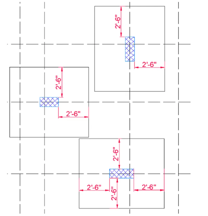
- Next we have to sketch the column and footing with the needed dimensions.
- We take the two columns length is 9" and the width is 24".
- We take the one column length is 9" and the width is 18".
- Next we do the offset of 2'-6" horizontally and vertically from the columns.
Step-6
- Next we have to sketch the column and footing with the needed dimensions.
- We take the column length is 24" and the width is 24".
- Next we do the offset of 2'-6" horizontally and vertically from the columns.
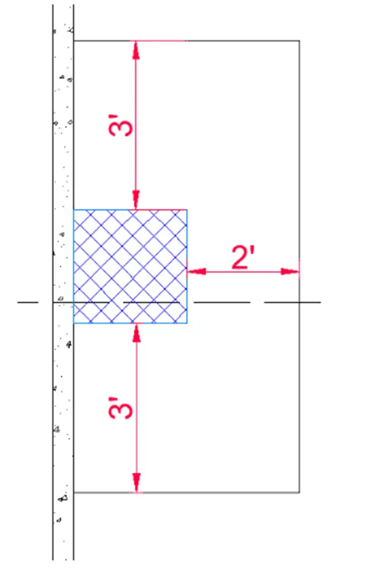
Step-7
- Now we have to take the two columns with the length of 24" and width of 24".
- And once more we require giving another two columns with the size of 9" x 24".
- And put the columns in the needed position and draw the footing with reference to the column placement with the standard dimensions as given in the picture.
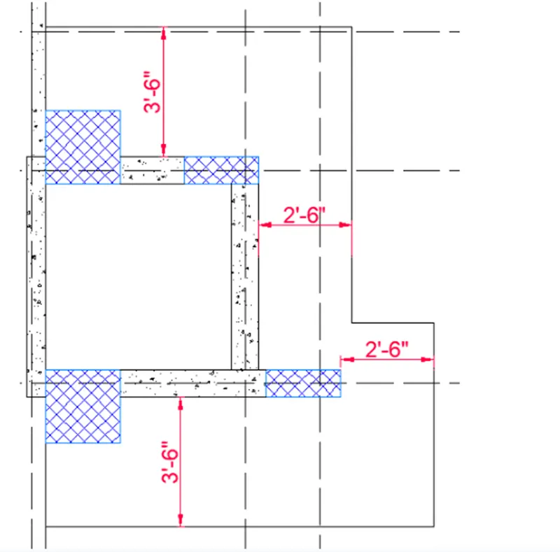
Step-8
- Next we require giving column size as 9" x 24".
- Here we take the two columns that the column sizes are detailed above.
- And once more we sketch the footing with reference to the column sizes.
- Here there are two columns, one column is placed horizontal and one column is placed vertically. • From first column we take the offset of 3-07 and another column with the 2'-6" length we take the offset.
- By utilizing this dimension we sketch the footing.
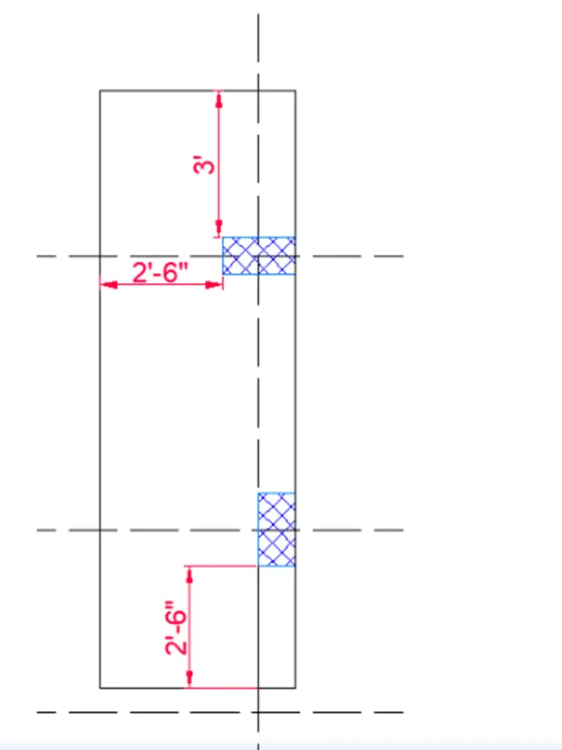
Step-9
- Here we have the two columns with two footings.
- We sketch them individually; the first footing is sketch with the reference of the column size.
- Next we do the offset of 2'-6" horizontally and vertically from the first column.
- Next we do the offset of 3'-0" horizontally and vertically from the second column.
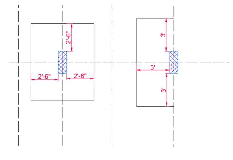
Step-10
- Accordingly from the above footings and columns, we draw the footings with the reference of the size of the columns.
- Here there are two columns in the first footing; the first column size is 24" x 24".
- And next column size is 9' x 24", by utilizing this Colum sizes we sketch the footings.
- Next once more we sketch another footing beside of it.
- In the other footing, the column size is 9" x 24".
- Next we do the offset of 3'-0" horizontally and vertically from the columns.
- With reference to the column size, another footing is also drawn.
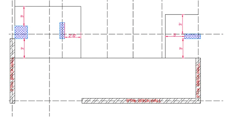
RESULT: The raft foundation was drawn with the accurate dimension methods in the AutoCAD.
FINAL RESULT:
- The elevation, plan, carcass elevation, side elevation and sections.
 2.The floor plan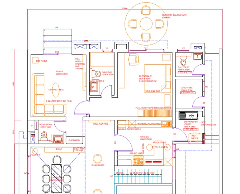
 3.The kitchen Layout :
 4.The Column details :
 5.The raft foundation :