Creating a Wardrobe detailed drawing, Floor Plan, Kitchen Layout and Column Detail using AutoCad
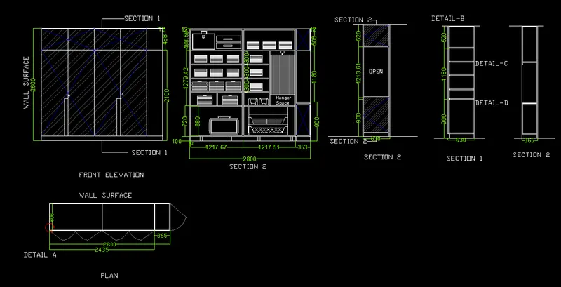
Question 1. Draw the elevation and details of a wardrobe as shown in the Figure below. After sketching, you need to provide the dimensions and text with the use of layers. Use proper text styles and dimension methods to document it. Also, assume dimensions, wherever needed.
Note: All dimensions are in mm.
Answer:
AIM: To draw the elevation and details of a wardrobe.
Introduction: AutoCAD is a computer aided software and drafting application.
In this challenge i am going to use various AutoCAD tools in order to complete this challenge.
Like line tool,rectangle tool,offset tool,hatch command,arrar command,polyline,circle,arc,Dtext,multileader,DIM linear,DIM continue to create the dimension lines,copy command,layers,fillet,trim and so on. Let's get started, the procedure of this sketch is explained below.
Procedure:
- Firstly open AutoCAD software.
- Select start from the scratch.
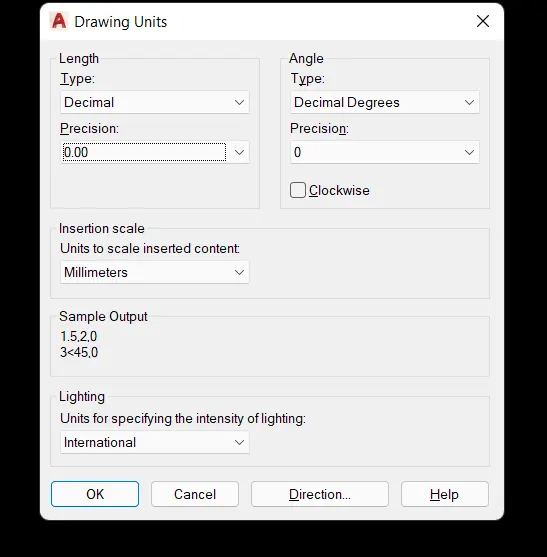
- Set the units to decimal and select OK.
- Now set the limits.
- Just type LIM in the command line and then press enter.
- Set the limits as lower left corner as 0,0 and the upper right corner as 1000,1000.
- Now type z in the command line and then press Enter and agin type e and then press Enter. Now the AutoCAD screen is zoom out.
- Using line tool we can draw the outline of the wardrobe.
- To invoke the line tool just type L or Line in the command line and then press Enter.
- After specify the first point.
- Specify the next point as @2800,0 and then press Enter.
- Now specify the next point as @0,2600 and then press Enter.
- Specify the next point as @-2800,0 and press Enter.
- Specify the next point as @0,-2600 press Enter or click on the CLOSE option.
- The boundary line of the wardrobe is completed.
- Now the offset command.
- Type O or Offset in the command line and then press Enter.
- Give the offset distance as 12 and 488 from the upper line. And give the offset distance as 2435 and 1217.5 from the left side corner respectively.
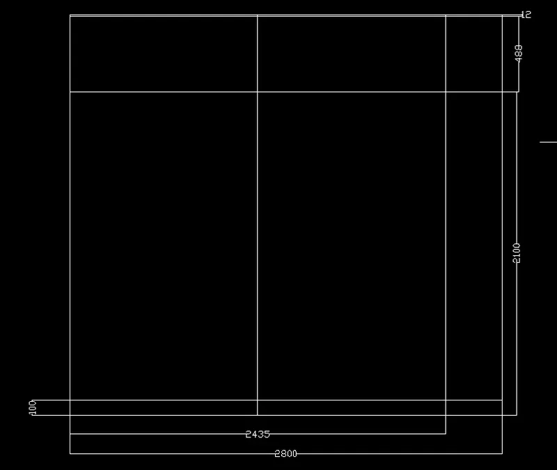
- Now give the offset of 608.75 and 365 from the left side.
- And now trim the all unwanted lines using trim tool.
- Type Trim in the command line and then press Enter.

- In the command line type Rec or Rectangle and then press enter.
- Specify its first point and then type d (dimension) and then press Enter.
- Specify the length and width of the rectangle and make the handle using rectangle tool.
- By using circle command we can draw the lock of the wardrobe.
- Type C or Circle in the command line and then press Enter.
- Specify the radius.
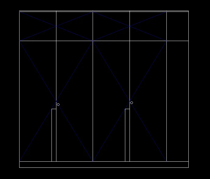
- In the command line type Qleader to give the annotations.
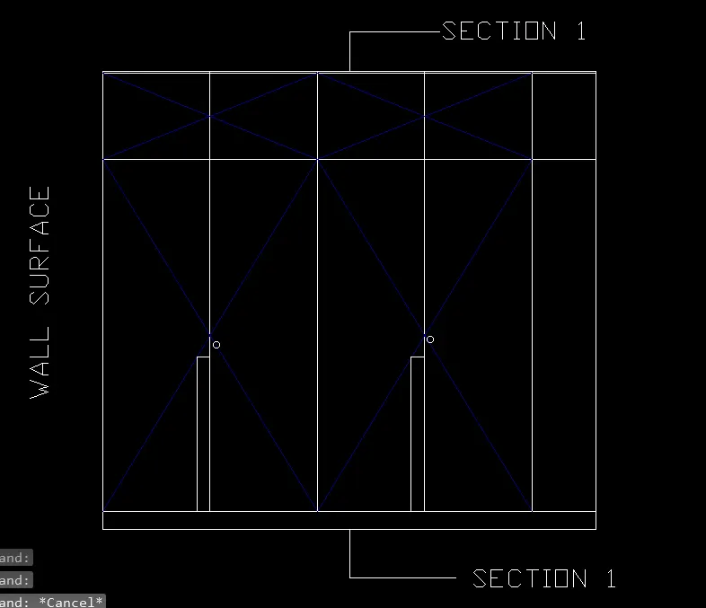
- Using Hatch command give the hatch in the inner boundary.
- And give the dimensions using DIM linear command.
- Type DIMlinear in the command line and then press Enter.
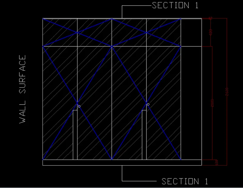
- This is the Front Elevation of the wardrobe.
- Now use XL command to make the plan of the wardrobe.
- Type XL in the command line and then press Enter.
- For making the plan of the wardrobe we need vertical line as the extension lines.
- So click on the vertical line and then press Enter.
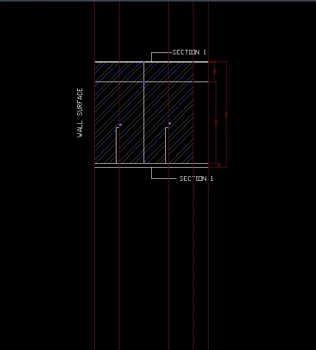
- Draw a line according to the extension lines and give it a height of 630.
- After that trim all the unwanted lines using the trim command.
- Type Trim in the command line and then press Enter.

- Now give the annotation using singleline command.
- Give the text height 100 and the angle 0.
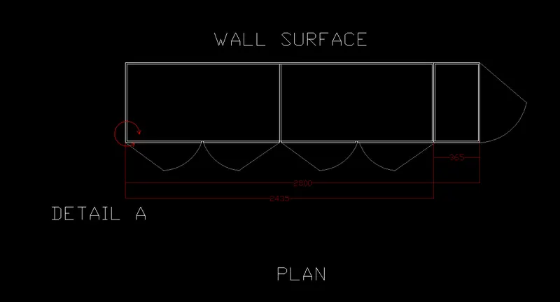
- Now draw three rectangles of size 600 X 2700mm,600 X 2700mm and 300 X 2700mm.
- Project these lines from the previous drawing using command XL just type XL in the command line and then press Enter.
- Mark the shelves of the wardrobe.
- Name it as side elevation,section1 and section2.
- Now use hatch tool wherever is necessary.
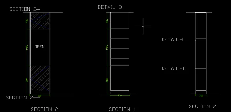
RESULT:
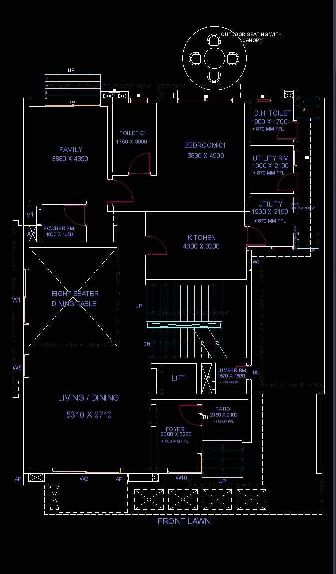
QUESTION2. Draw the floor plan as shown in the Figure. Use the proper drafting tools to sketch the plan. Do not hatch or draw the furniture.
Answer.
AIM: To draw the floor plan using the different AutoCAD tools.
Procedure:
- Set the units to the decimals.
- Enter command "PDFIMPORT" and then click on the required file.
- Now select the page of the floor plan as shown below:
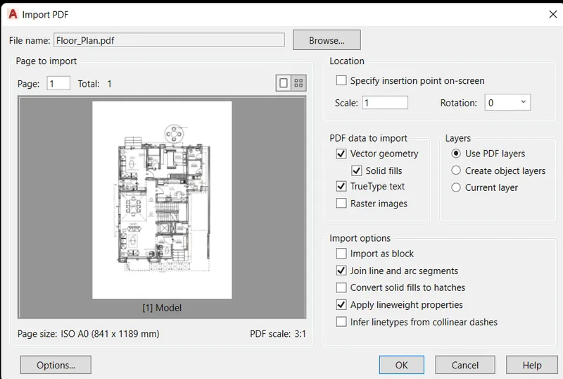
- By taking the reference of the diagram draw the floor plan and adjust the scale accordingly.
- After completing the drawing remove the imported file pdf.
- Mark the dimensions of the diagram using the dimlinear tool.
- Type DIMLINEAR in the command line and then press Enter.
- Now create layers for rooms,windows,dimensions,text,linetype etc and assign it accordingly to the plan.
RESULT:
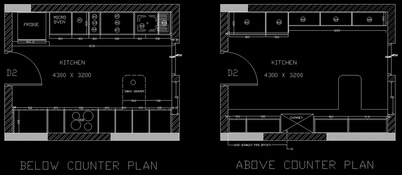
Question 3. Create the Kitchen Layout as shown in the Figure below. Also, use proper dimension techniques to dimension the kitchen layout.
AIM: To draw the kitchen layout using AutoCAD.
Procedure:
- First of all set the units.
- Type UN in the command line and then press Enter.
- Set the units in the dimstyle to decimal.
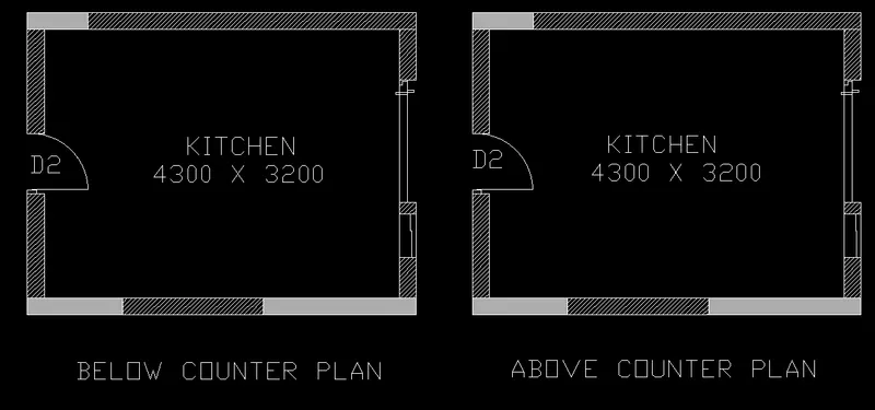
- Now draw a rectangle of 4500 X 3400 and give the offset to the rectangle of 200mm.
- Draw the door of dimension 760 X 2100 mm as shown in the figure.
- Create a text using single text command type "KITCHEN 4300 X 3200" at the centre of the figure.
- Hatch the offset area with two different hatches.
1. ANS131, SCALE = 20.
2. SOLID with transperancy 50.
- Now make two exact copies of this diagram using the copy command.
- Type CO or Copy in the command line and then press Enter.
- Select the base point and copy the rectangle to the different position.
- Write "Below counter plan" and "Above counter plan" below the both diagram.
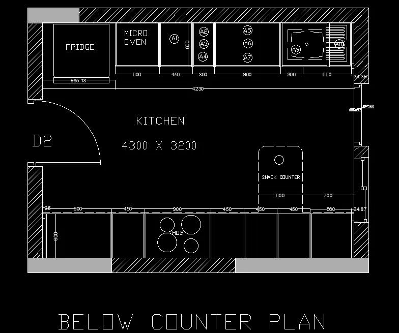
- Now in the below counter plan draw fridge,various types of shelves,sink,gas stove etc and all these can be drawn by using rectangular tool.
- Just type Rec or Rectangle in the command line and then press enter.
- And also mark the dimensions using dimlinear command.
- Similarly in the Above counter plan draw various other shelves,chimney area using the rectangle tool.
- Just type Rec or rectangle in the command line and then press Enter.
- Now mark the dimensions using the dimlinear command. Just type DIMLINEAR in the command line and then press Enter.
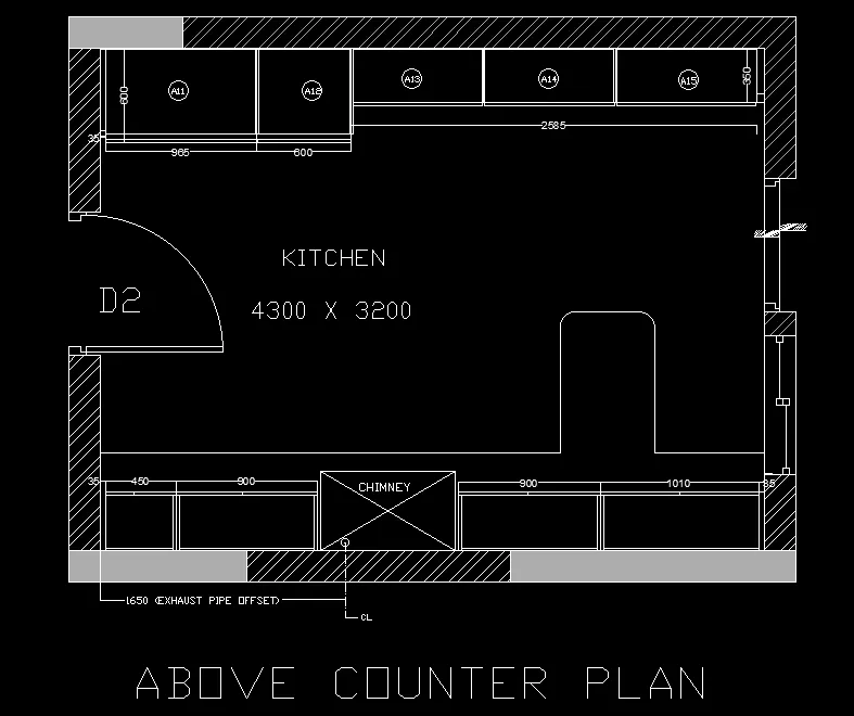
- Text style can be arial and the height for the text is 80mm.
RESULT:
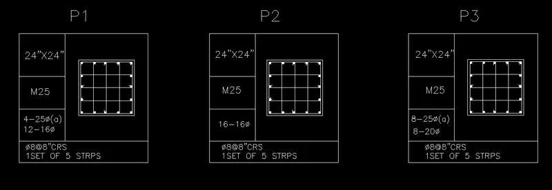
Question 4.Sketch the column details as shown in Figure. Insert dimensions and text in the figure.
Answer.
AIM: To sketch the column details using AutoCAD tools.
Procedure:
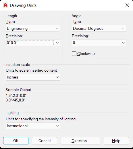
- Set the units to Engineering.
- Set units in the dimstyle to Engineering.
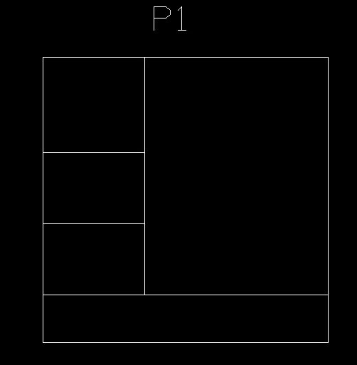
- Draw a square of size 60" X 60".
- Divide the square in rows and column as shown below.
- Now give it naming as P1.
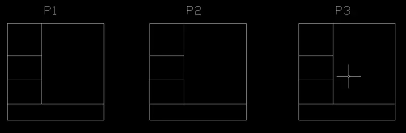
- Now make two another copies of this sketched figure and named as P2 and P3 respectively.
- Now draw a square of 24" X 24" and give the offset of 1" to the ouside of the square.
- Inside this square draw three vertical and three horizontal lines with offset distance of 6".
- Now draw the circles along with with radius 0.5.
- Type C or Circle in the command line and then press Enter.
- Click on the tan tan radius option and click on the two tangents and draw the circle by giving them of a radius 0.5".
- Now type DO or donut and press Enter.
- Outer diameter as 0 and inner diameter as 1.0"
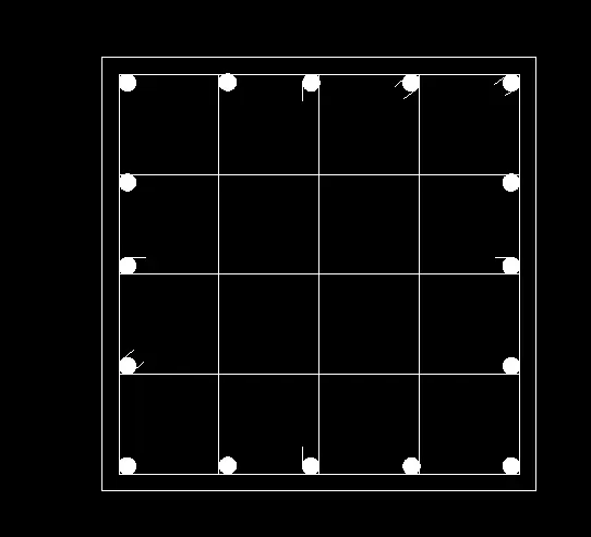
- Now place this diagram in P1,P2 and P3 squares.
- Give the text using single line text command. Give the font height as 3.5" and angle 0.
RESULT:
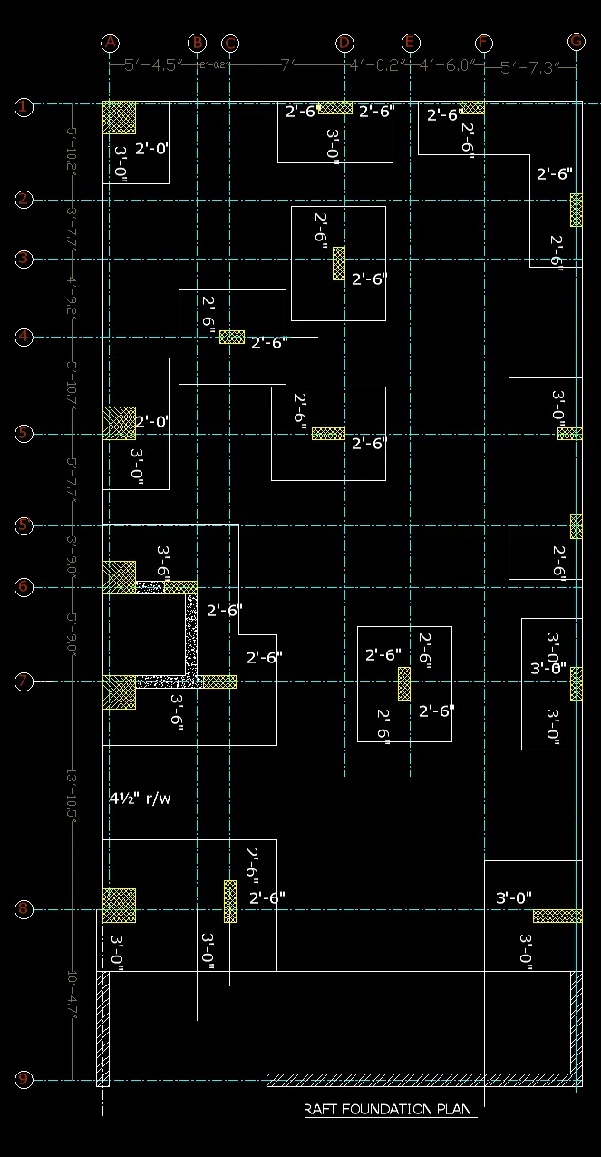
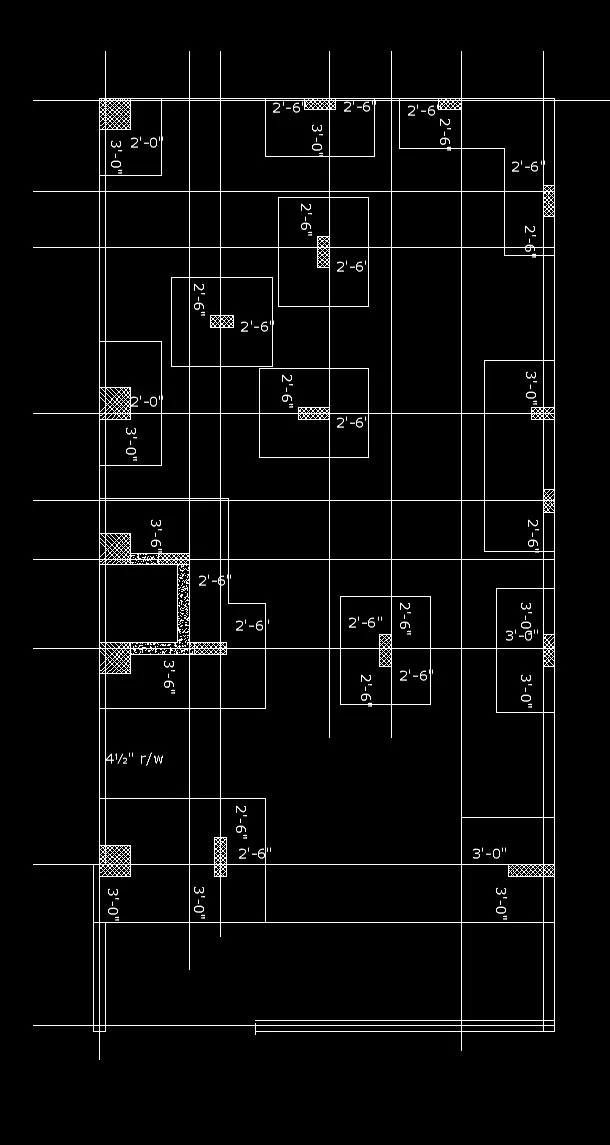
Question 5.Draw the Raft Layout as shown in the Figure. Assume the column size as per your knowledge. You can take the sizes as: 24”x24”, 9” x 24”, 9” x 18”, and 9’ x 24”.
Answer.
Aim: To draw the raft layout using different AutoCAD tools.
Procedure:
- Set units to engineering.
- Set units in the dimstyle to engineering.
- Now enter the command "PDFIMPORT" in the command line and then press enter.
- Now select the page of raft foundation.
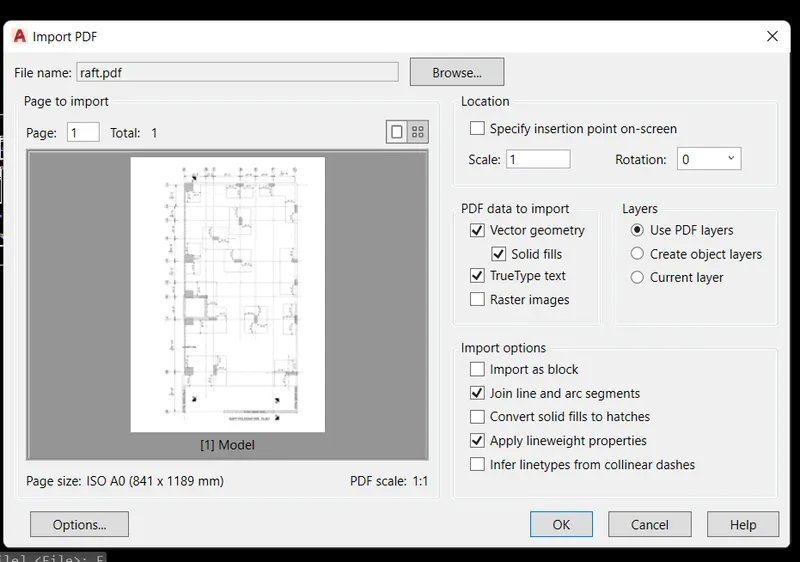
- Now taking the reference of diagram draw the raft foundation plan.
- Now adjust the scale of the diagram accordingly.
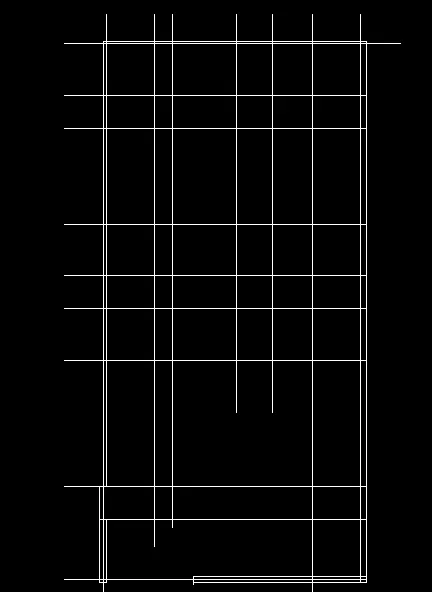
- After finishing the file remove the imported pdf file.
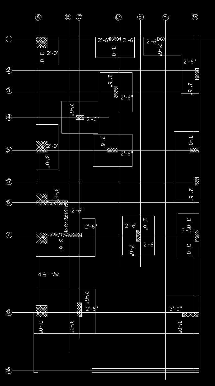
- Make the dimensions of diagram using the command dimlinear.
- Now create the layers and assign it accordingly.
- In this drawing three different hatches are used named as:
a. ANS137 with hatch patterns scale 20.
b. AR-CONC with hatch pattern scale 0.6.
c. ANS132 with hatch pattern scale 10.
RESULT: