Creating a Wardrobe detailed drawing, Floor Plan, Kitchen Layout and Column Detail using AutoCad
Aim: To create wardrobe detailed drawing, floor plan, kitchen layout and column detail using Autocad software
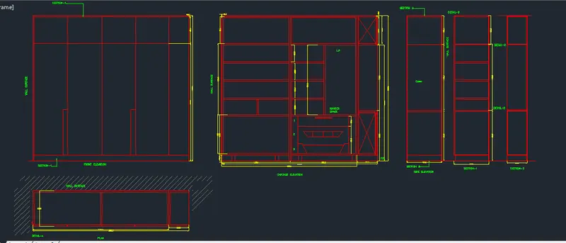
Introduction: Creation of wardrobe detailed drawing consists of a Front elevation, side elevation and carcase elevation
1)
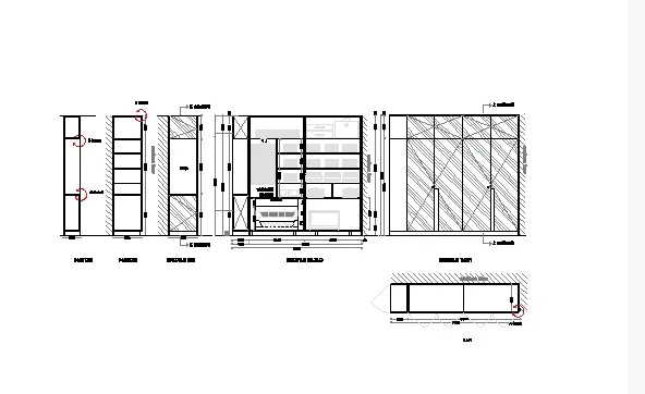
Aim: To draw a wardrobe detailed drawing and its elevations by using autocad
Procedure:
- Firstly we have to go to startmenu and open the Autocad 2014 software
- Then type the startup command in the command box and give the value1
- Go to Application menu and go to new file
- Create new file dialogue box opens and set the units to decimal and precision 0.0 and press ok
- Go to units command in command box and set the units to decimal and precision is 0.0 and insertion scale as millimeter
- Go to limmax command and set the limits to 1000 and press enter
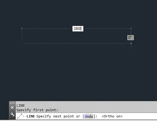
- Go to Line command in command box and draw a line of length 2800mm for the creation of plan
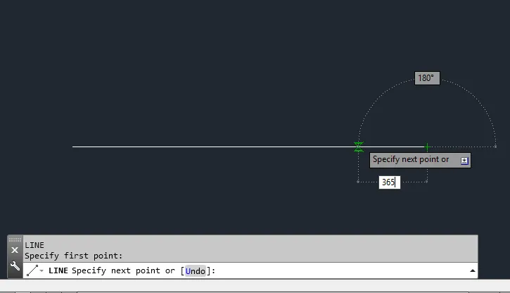
- Take 365mm line from the left end of the 2800mm line
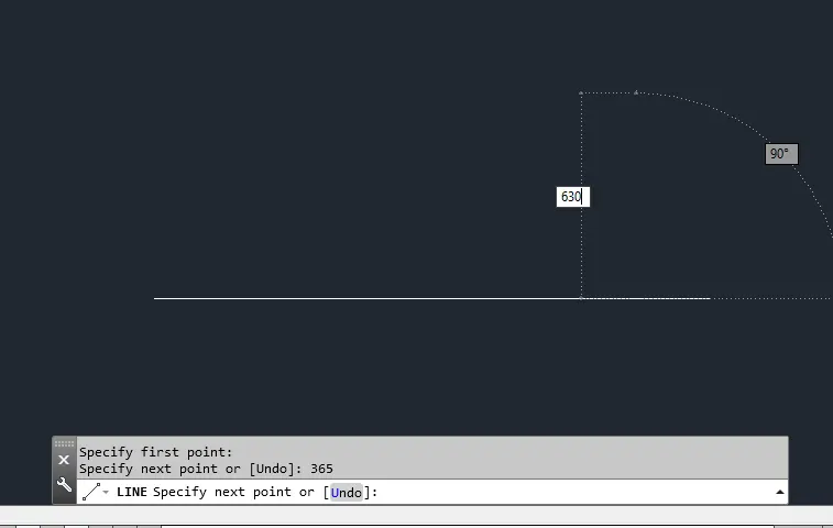
- And 630mm length of the wardrobe is drawn by using a line tool
- Take a offset 25mm by using offset tool and draw a offset of 25mm inside the wardrobe
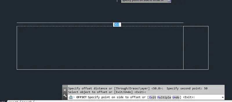
- Draw a line in the midpoint of the wardrobe
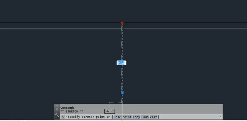
- The plan is now drawn and thus followed by elevations
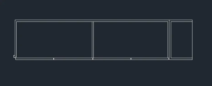
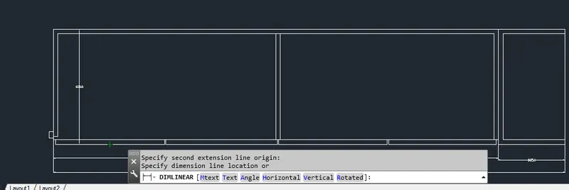
- Dimension the plan using suitable dimension style dimlinear style
- And also add the text to the plan using single text command
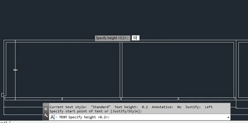
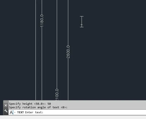
- Go to single text and specify height as 50mm and press enter
- Add the text to the plan and come out of the text command and press escape
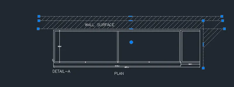
- Type Ha in the command box and go to hatch command and select ANSI31 hatch option and hatch the wall surface
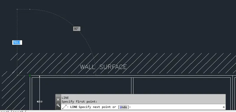
- Take a line tool by line command and draw a elevation from the plan of length 2600mm
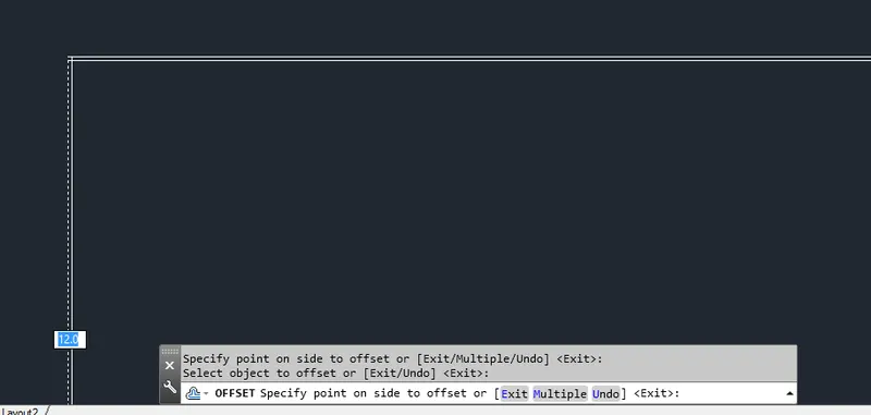
- Extend the lines from the plan and also the offset from the plans of 12mm
- Take a offset of length 2100mm from the bottom line using offset command
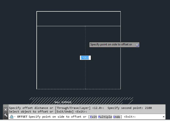
- Again 100mm from the bottom of the front elevation
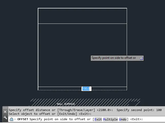
- And 365mm offset from the left of the front elevation
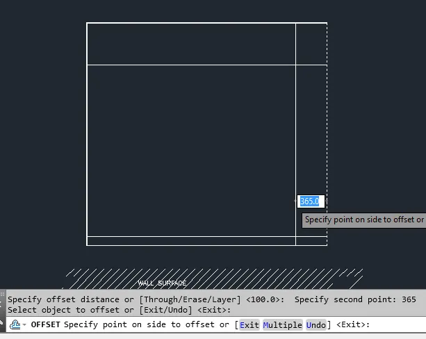
- Add a text by using qleader command
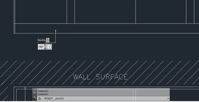
- Project the line from the front elevation to draw a carcase elevation
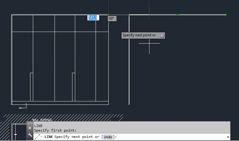
- Take 25mm offset inside the frame of wardrobe
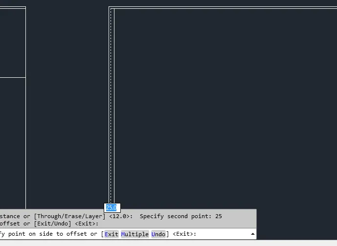
- Take a offset of 488mm downwards by using offset command
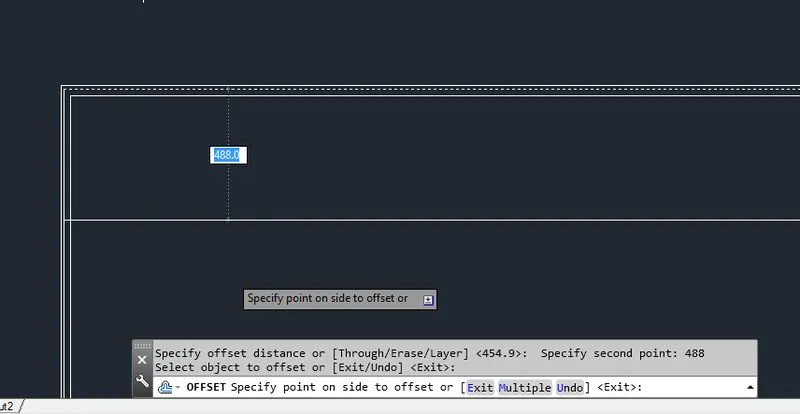
- And again take 1280mm from the offset line by using offset comand
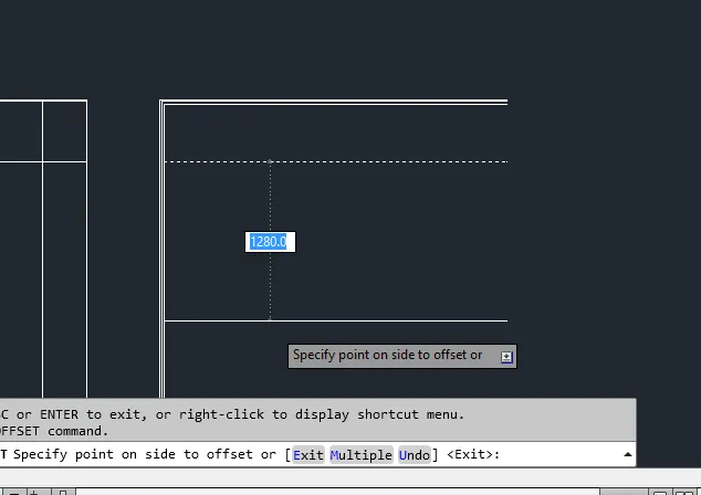
- Again 720mm offset from the 1280line by using offset command
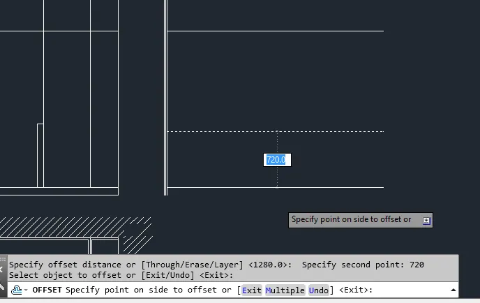
- Take offset by using offset command on the right side of a line of length 1223mm
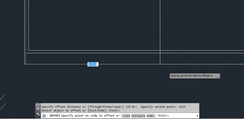
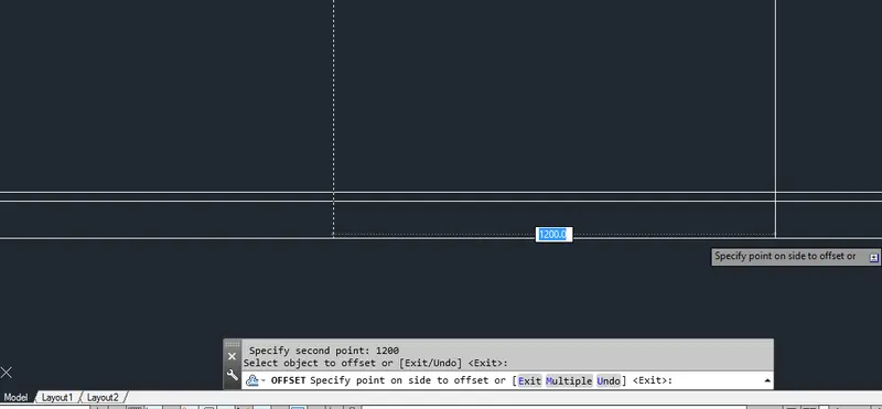
- Again offset of 1200mm using offset command from the 1223 mm line
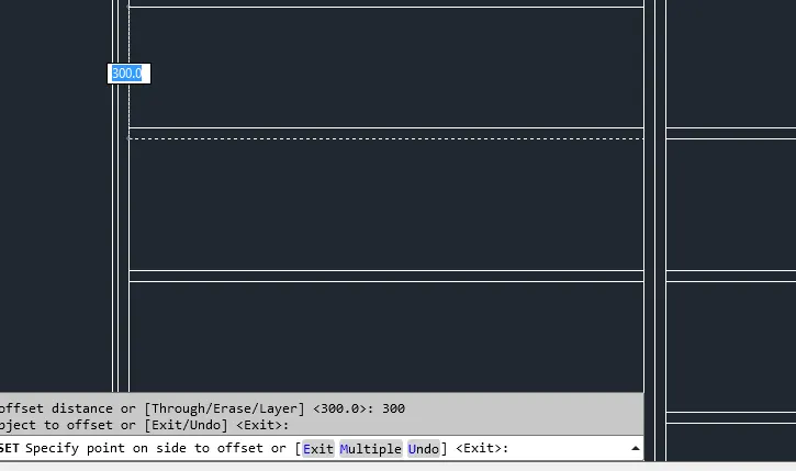
- Take 300mm offset from the 488mm line downwards
- Again take 25mm offset from the 300mm line
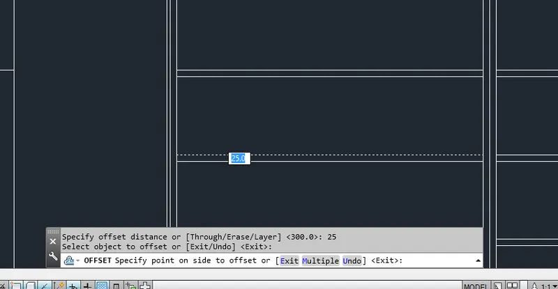
- Draw a line from the midpoint of the line by using line tool
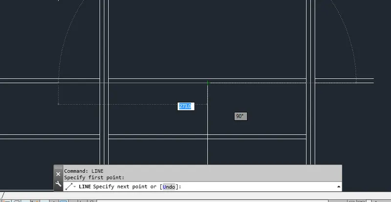
- Again take a offset of 25mm from the midline drawn before
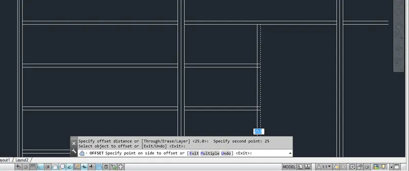
- Draw one rectangle over here using the line tool
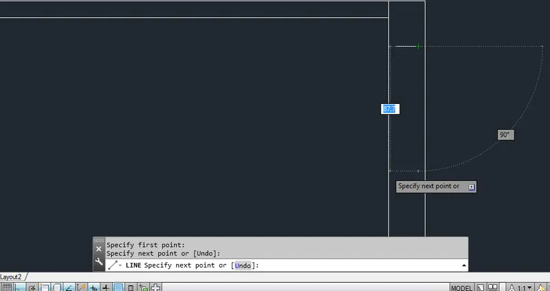
- Draw the cross line using line command over here
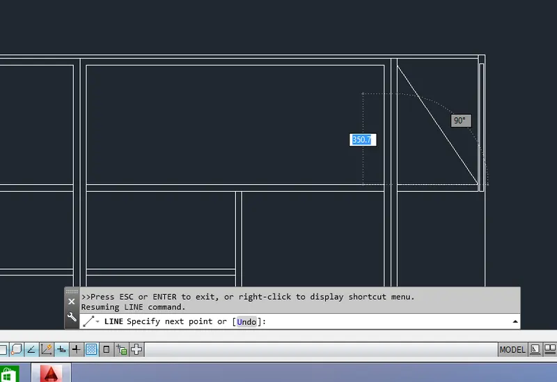
- Draw the line of length 900mm from the bottom of the wardrobe

- Draw a line from the end by using line tool
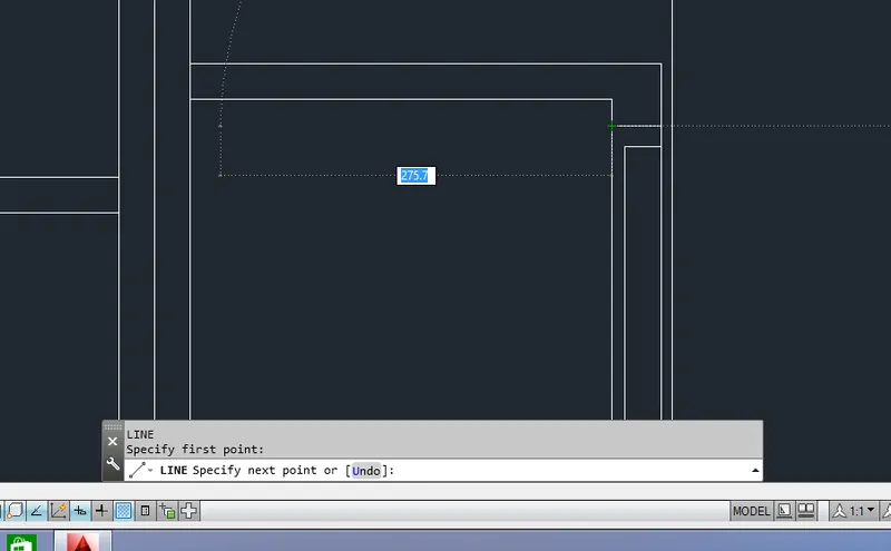
- Again draw a cross line over here by using line tool
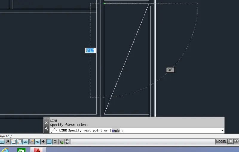
- Take 180mm line downwards from the line using line command
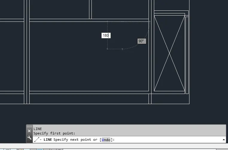
- Draw a horizontal line from the end of the 180mm line using line command
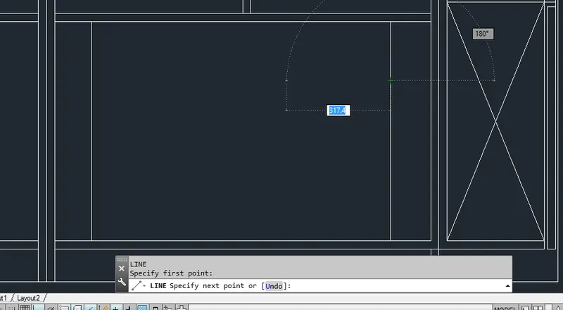
- Go to annotation tab and their go to linear option
- Dimension the carcase elevation by using dimlinear command
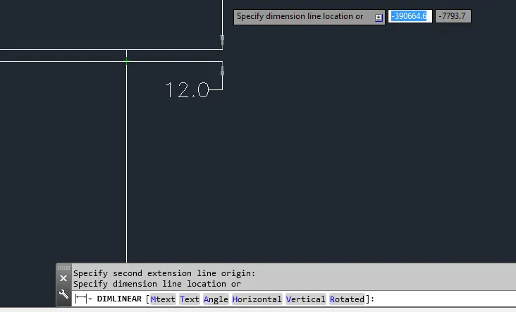
- And also to add text go to singleline text and give a height of 50mm and insert a text
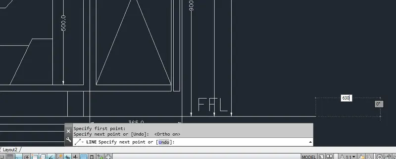
- Project the line from the carcase to draw a side elevation using line tool and draw a line of length 630mm
- Draw a line of length 900mm vertically upwards using line tool
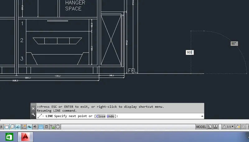
- Again draw a continous line of length 1180mm from the 900mm line using line tool
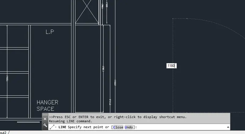
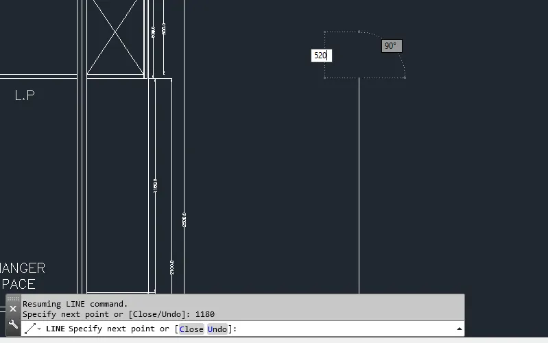
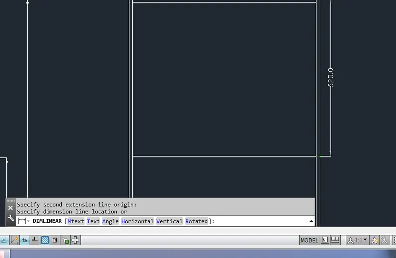
- Draw a continous line of length 520mm from the 1180mm line
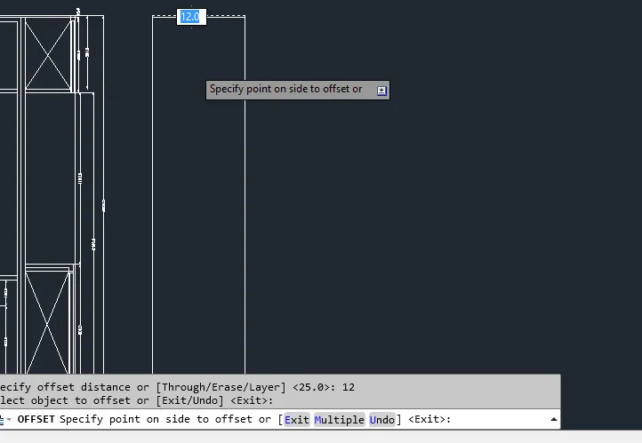
- Take a offset command and draw a offset of length 12mm from all the four corners of the elevation line
- Take a offset of length 100mm from the bottom of the line using offset command
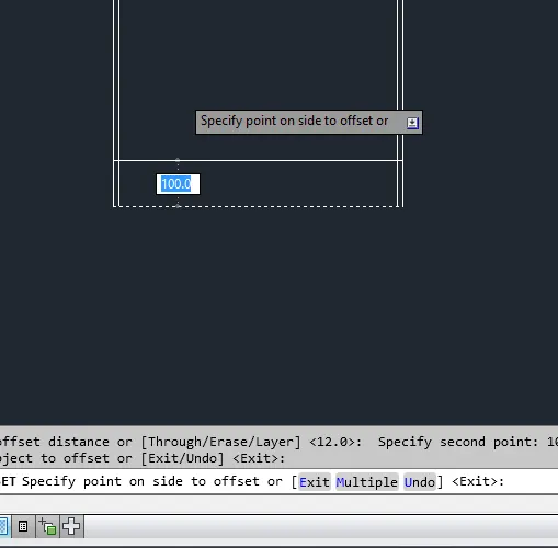
- Again take a offset of 800mm from the 100mm line vertically upwards
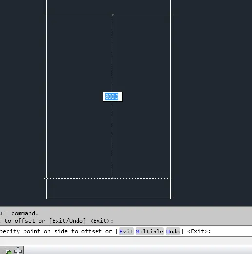
- Take a offset of 1180mm from 800mm line using offset command
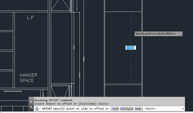
- Dimension the side elevation from dimlinear dimension tool
- Take a Qleader command and insert a text by using qleader command tool
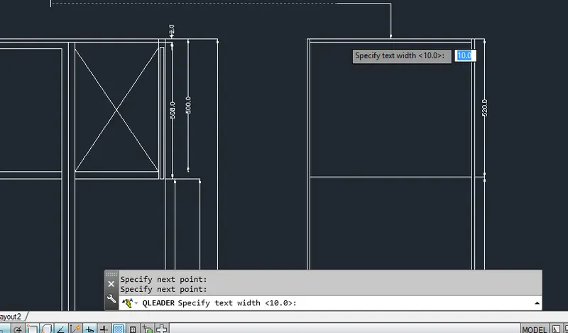
- Project the line from side elevation to draw a section 1 in detail using line tool
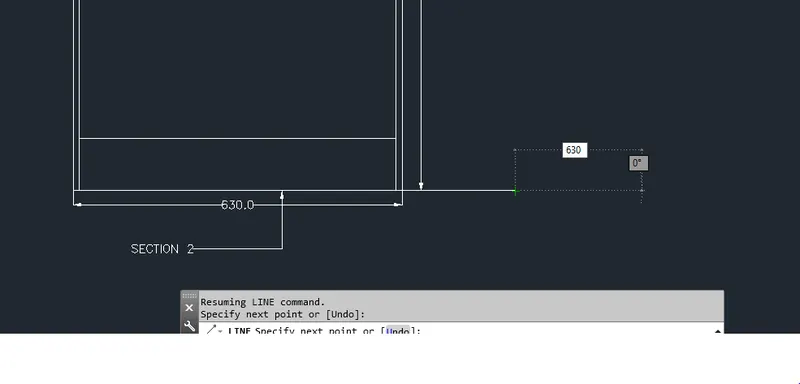
- Take offset of 12mm by using offset command
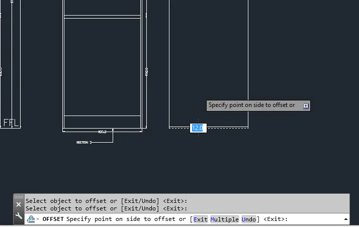
- Take a offset using offset command of length 900mm vertically upwards
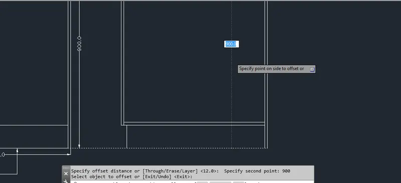
- Take a offset of length 12mm downwards using offset command
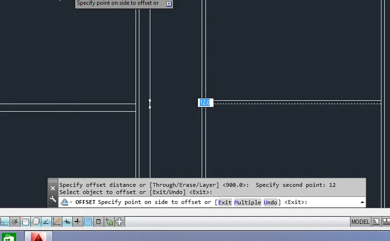
- Again project the 1180mm line from the side elevaation
- And project the lines fro the carcase elevation
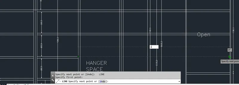
- Take the half of the section 1 to draw a setion-2 elevation
- Take a line of length 365mm using line tool
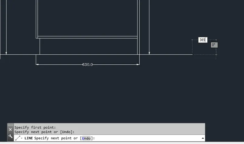
- Project the lines from the section-1 elevation using line tool
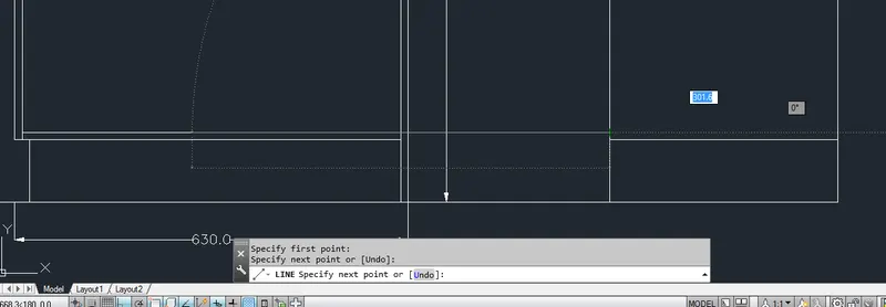
- After sketching the elevation, go to la command layer properties dialogue box will open
- Add new layers with the option of add new layer and create the various layers for dimensions and texts and assign in the elevation
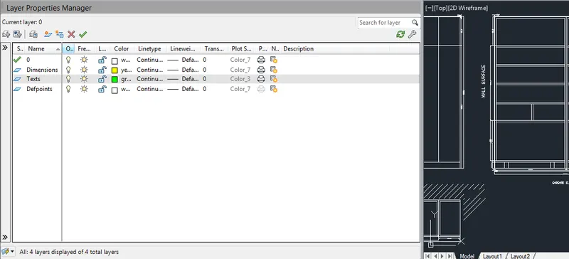
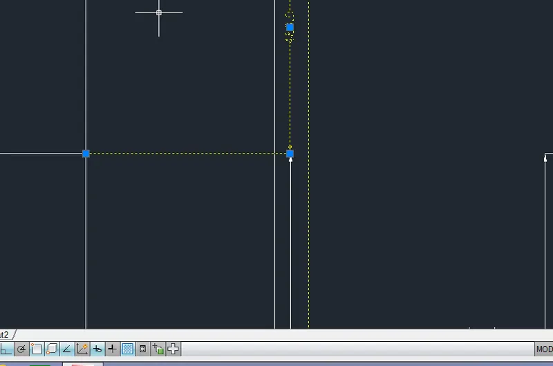
- Assign the dimensions to the created layers
Result:
2)
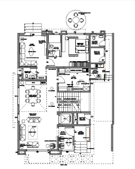
Aim: To draw a floor plan as given in the figure by using Autocad
Procedure:
- Go to startmenu and open the Autocad 2014 software
- Go to startup command and give value 1 in the command box
- Set the units to decimals and precision 0.0
- Go to units command and set the units to decimal and precision 0.00 and insertion scale as millimeters
- Go to limmax command and set the limits to 500
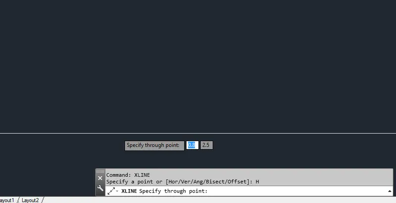
- To draw a plan go to xline command and draw a horizontal line using xline command
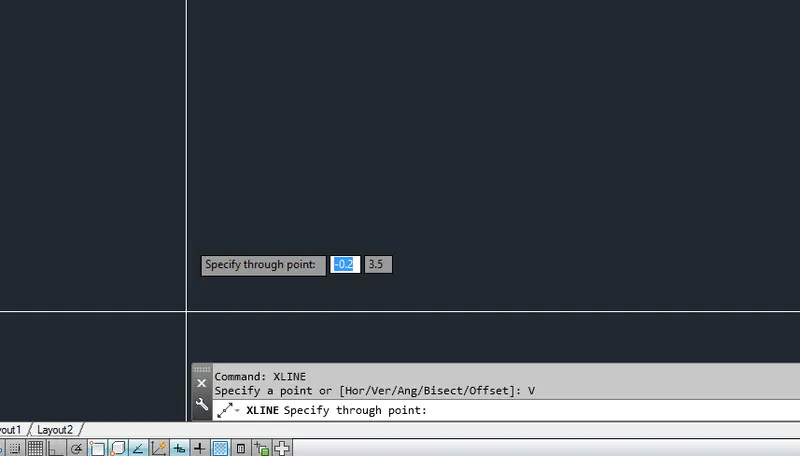
- And aslo draw a vertical line using xline command
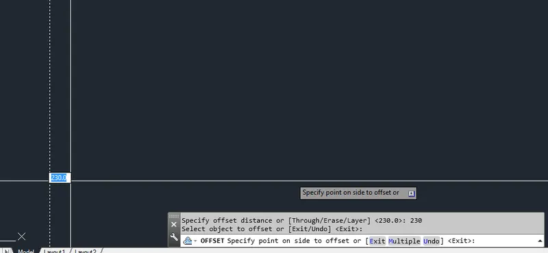
- Take a offset command and take a offset of 230mm for exterior wall thickness
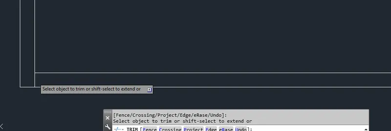
- Trim the unwanted line using trim command
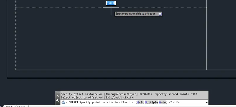
- Take a offset of length 5310mm towards horizontal axis using offset command
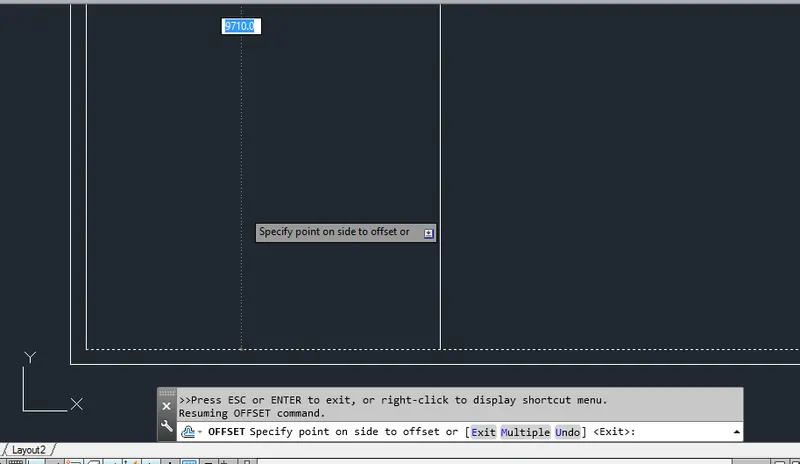
- Take offset of length 9710mm vertically upwards using offset command
- Also take the 230mm offset by using offset comand for wall thickness

- Leave some space for ventilator and then draw a powder room
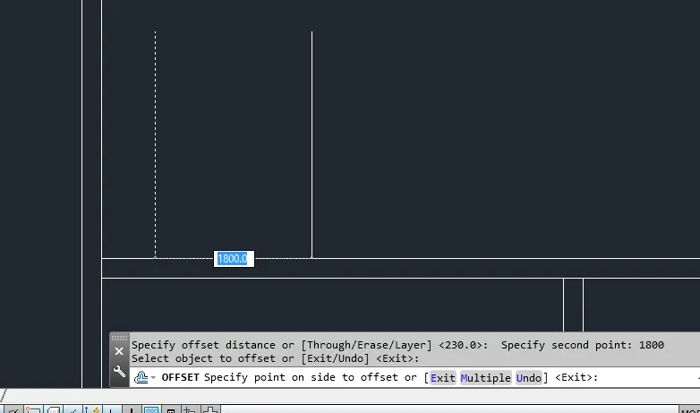
- Again take a offset of length 1800mm in horizontal axis using offset command
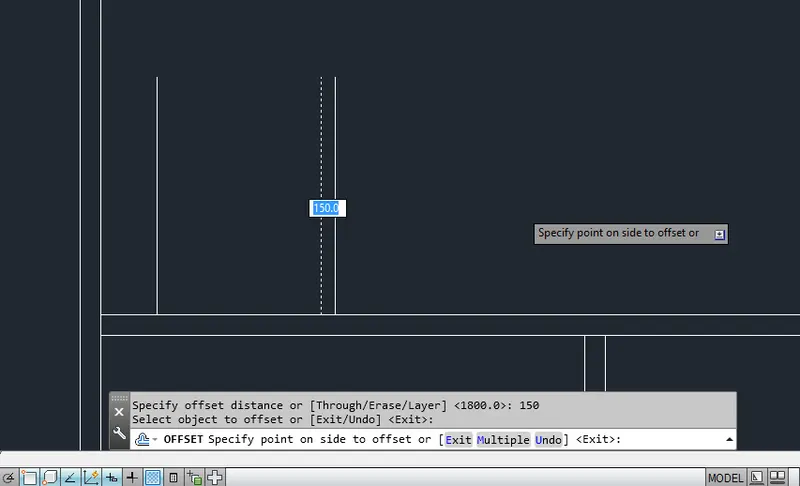
- Take a offset of 150mm for the inner wall thickness
- Draw a vertical line of length 1650mm using offset command
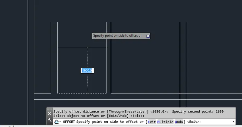
- Take a offset of 4350mm vertically upwards using offset command
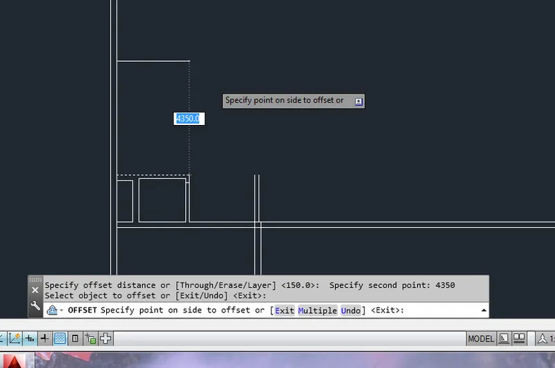
- And 3880mm offset in horizontal axis using offset command
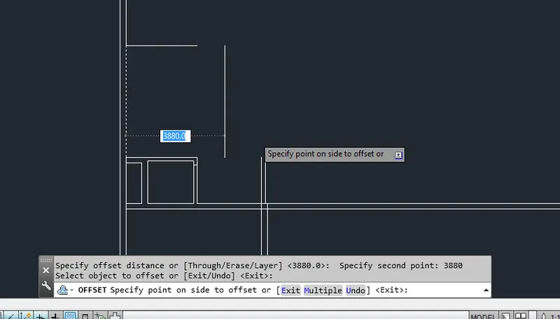
- Take a offset 1750mm horizontal axis using offset command
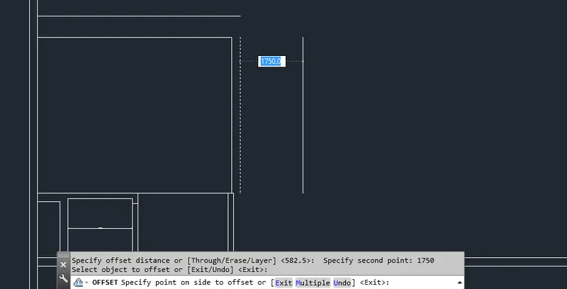
- Take offset of 150mm inner wall thickness
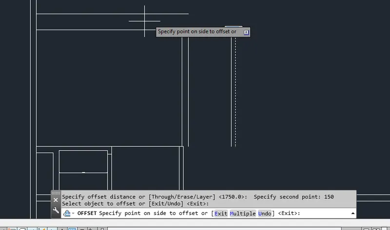
- Take offset 3830mm horizontaly to draw a Bedroom-01 using offset command
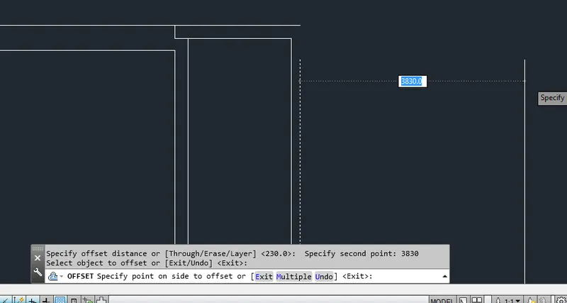
- Take offset of 1900mm horizontally using offset command and 150mm wall thickness
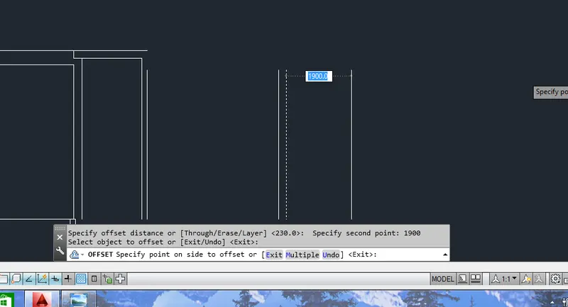
- Draw a line of length 3000mm vertically downwards using line tool
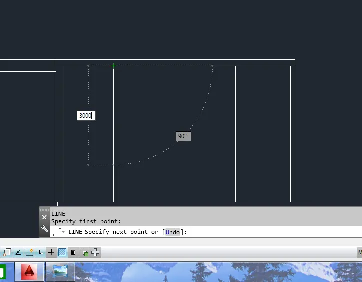
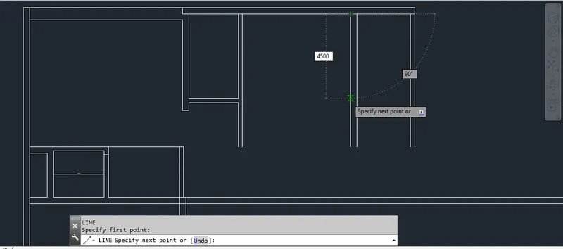
- And 4500mm line vertically downwards using line tool
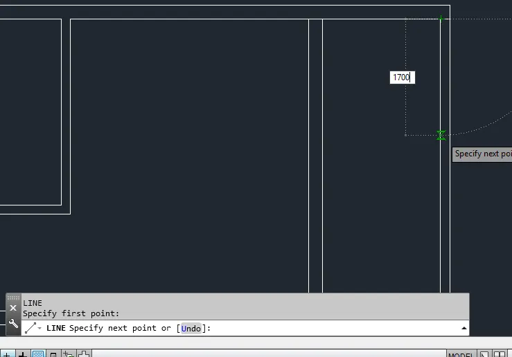
- Draw a line of length 1700mm using line tool for DH Toilet room
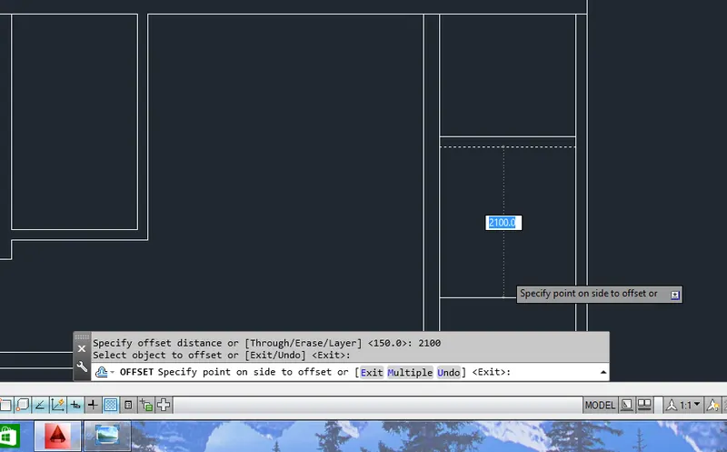
- Again take offset of 2100mm verticaly downwards using offset tool
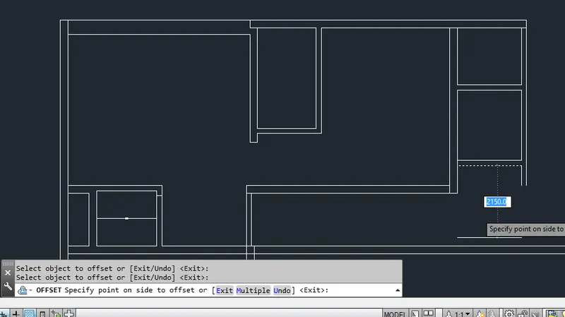
- Take a offset of 2150mm vertically downwards using offset tool
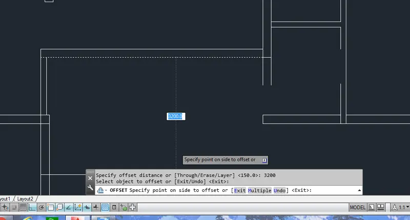
- Take offset of 3200mm vertically downwards using offset tool for kitchen room
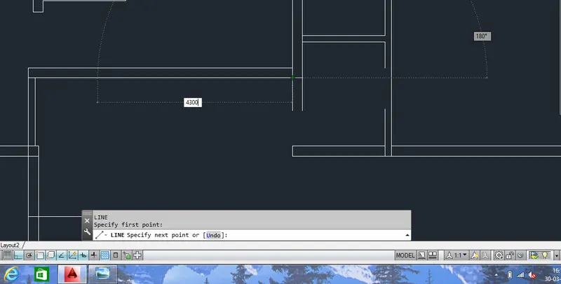
- Take a line command and draw 4300mm width forthe kitchen
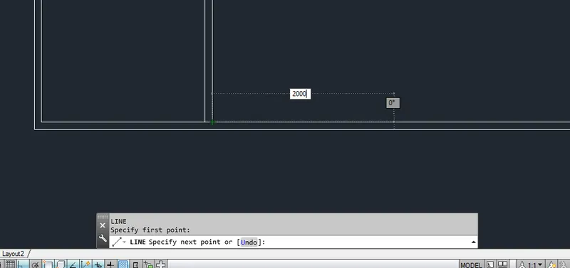
- Take a line command and draw 2000mm line width
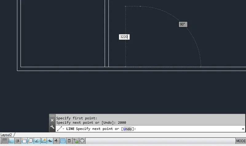
- And 3220mm vertically upwards using line tool
- Draw a line of length 2150mm using line tool

- Draw a cross line over here using line tool
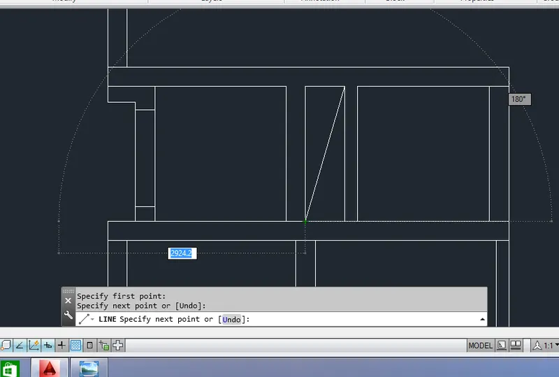
- Take a line command and draw a line for landing in staircase
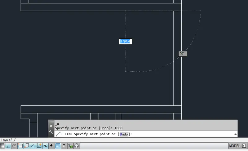
- Draw a thread of length 300mm using offset tool in the staircase
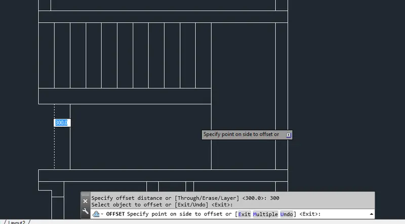
- Draw two jogged line using jogged command
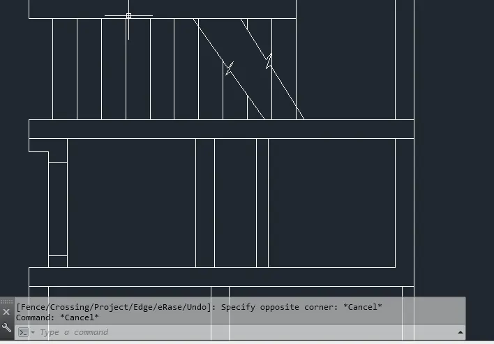
- Make these three lines as dash type line by using line type command
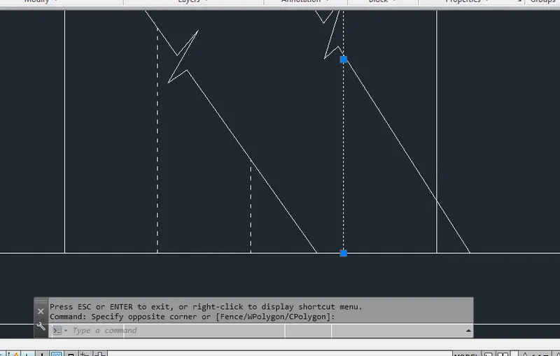
- Draw a planter box in the end of a plan
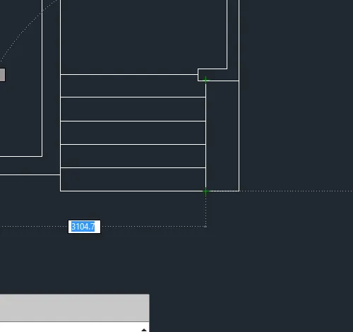
- Let us Assume standard door sizes of D1-1830X610mm
- D2-816X2134mm
- D3-762X2134mm
- D4-1981X711mm
- D5-2040X626mm
- Now draw a D1 size of the door by using line command
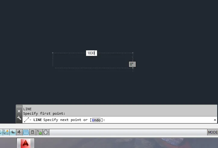
- Again draw a line of length 1830mm vertically upwards
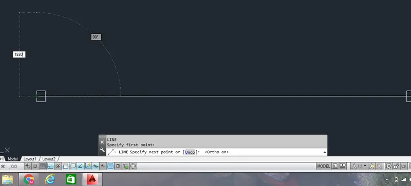
- Draw a circle from both the ends to draw a swing of a door
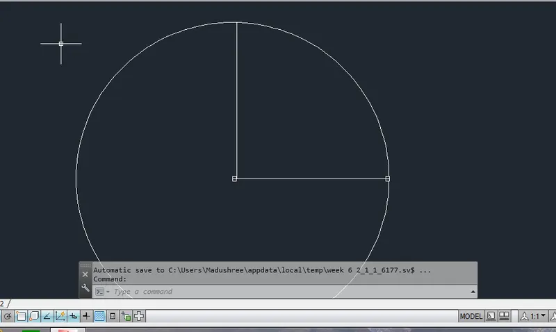
- Now the Door D1 is created
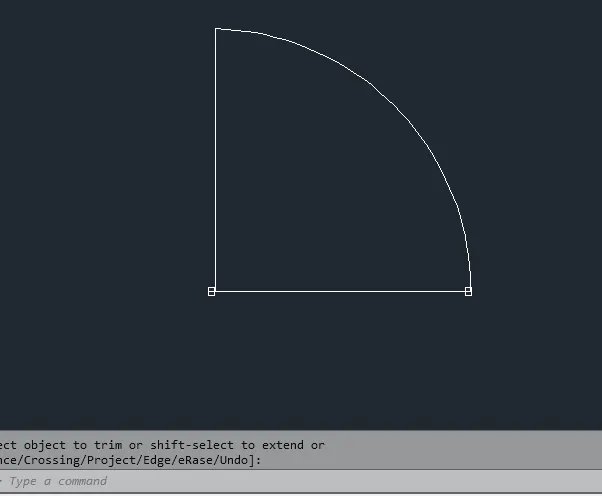
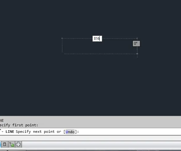
- Now take a line of length 816mm to draw a door D2
- And draw a line vertically upwards of length 816mm
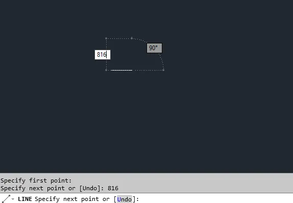
- Door D2 has been created
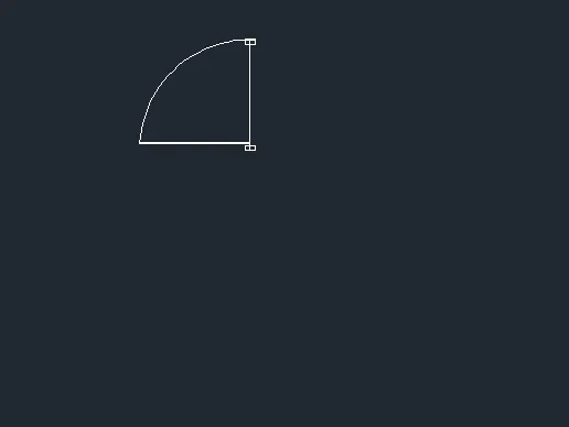
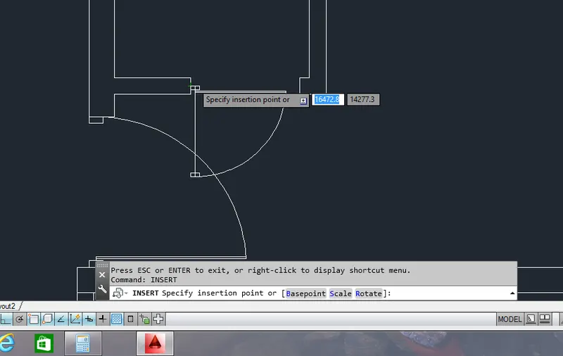
- Place the doors in respective position using block insert command
- Draw a window ventilator of length 457mm using line command
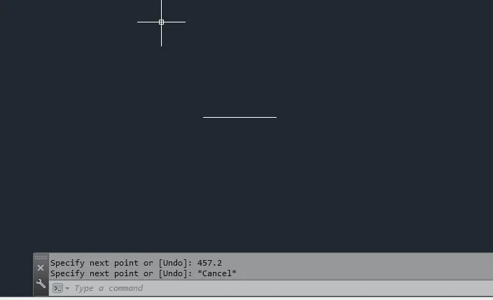
- Ventilator v1 is created
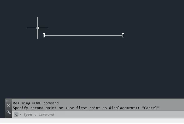
- Place the ventilator into the plan using move command
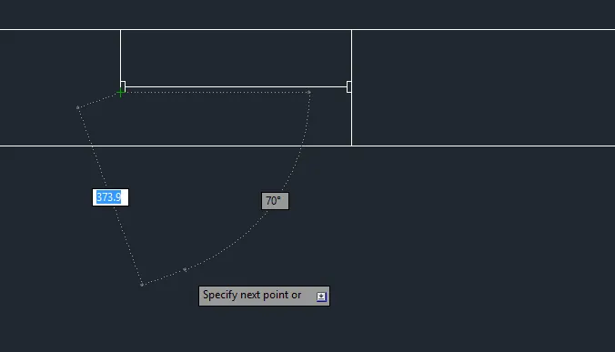
- Assume the window size and draw a window inside to the plan using line tool
- Assume, W1=36"X36"
- W2=24"X36"
- W3=24"X36"
- W4=72"X48"
- W5=36"X48"
- W6=72"X48"
- W7=2'X3'
- W8=4'X6'
- W9=1'7"X1'4"
- W10=6'X4'
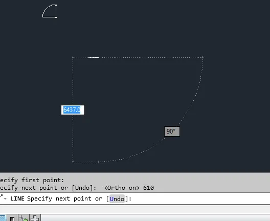
- Place the window into the floor plan using move command
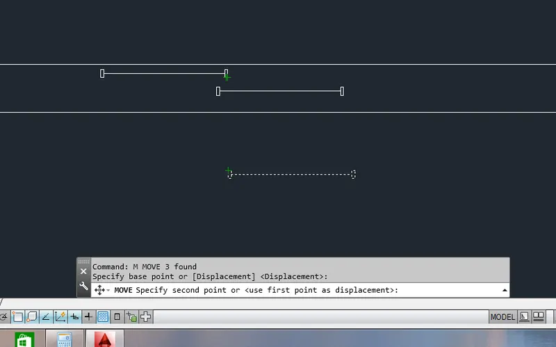
- Go to linetype and load the dash space line type and press ok
- Draw a dotted lines which shows the reference lines outside the floor plan
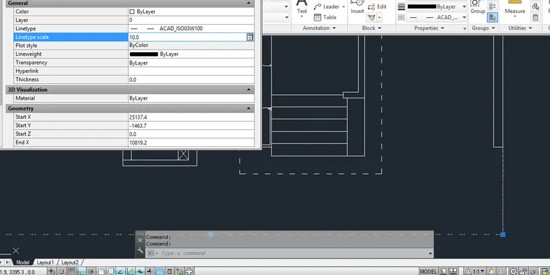
- Draw a front lawn using the line type dash space command
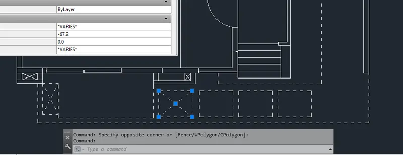
- Now Add a text into the plan using Dtext or single line text with a height of 50mm
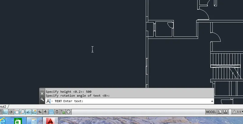
- Insert a text wherever it is necessary into the floor plan
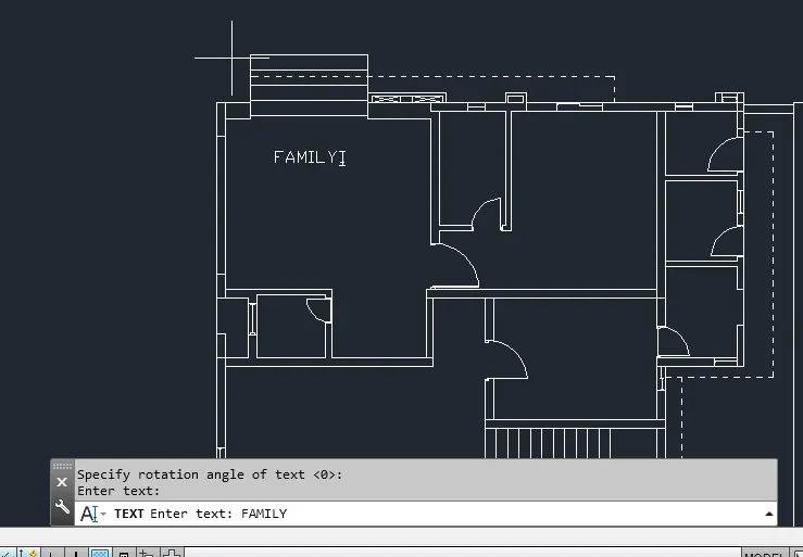
- Also dimension the plan wherever it is necessary
- Take suitable dimension style to dimension the floor plan
Result:
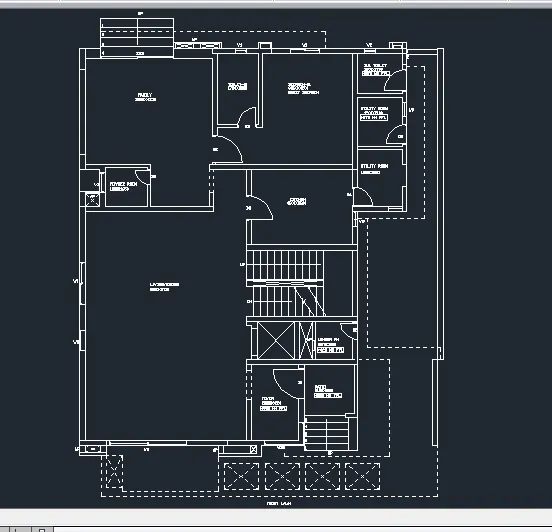
3)
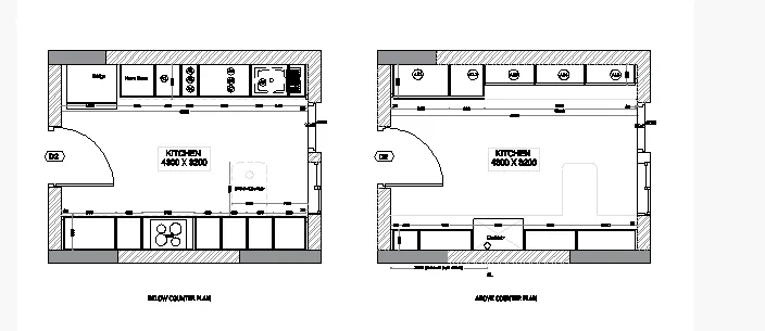
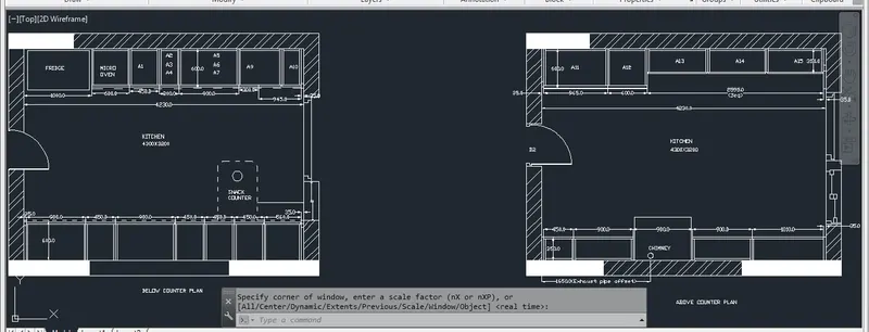
Aim: To create a given kitchen layout as shown in the figure using Autocad
Procedure:
- Go to startmenu and open the Autocad software 2014
- Go to command bar and give startup command and value 1
- Go to aplication menu and open a new file
- Create new file dialogue box opens and select advanced setup ,set the units to decimal, precision 0.0 and give finish
- Go to unit command and set the units to decimal and precision 0.0 and insertion scale as millimeters
- Go to limits command and specify lower left corner as 1000 and upper right corner as 1000
- Go to xline command and draw a horizontal xline using xline command and horizontal option
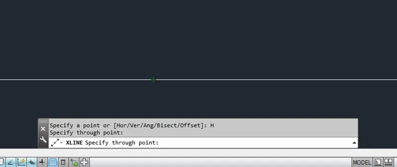
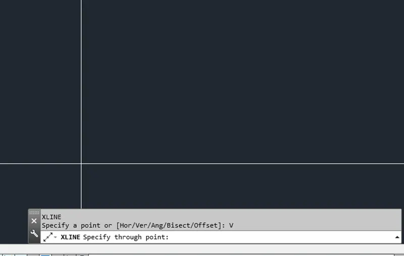
- And draw one vertical line using xline command tool
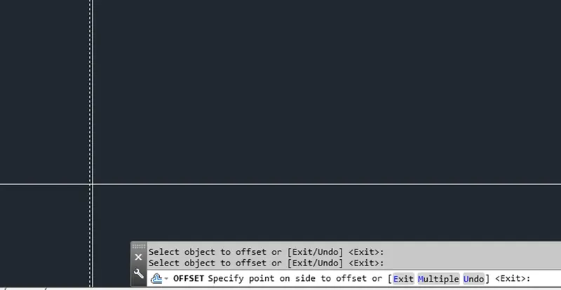
- Go to offset command and draw a offset of length 230mm, taken exterior wall thickness as 230mm
- Draw a offset of 230mm using offset toolt to both vertically and horizontal xlines
- Draw a line of length 35mm from 230mm wall using line tool with the height of 600mm
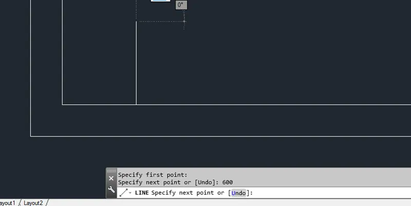
- Change the 600mm height line type to ISO dash space line type by line type command

- Now draw a line of length 35mm horizontally
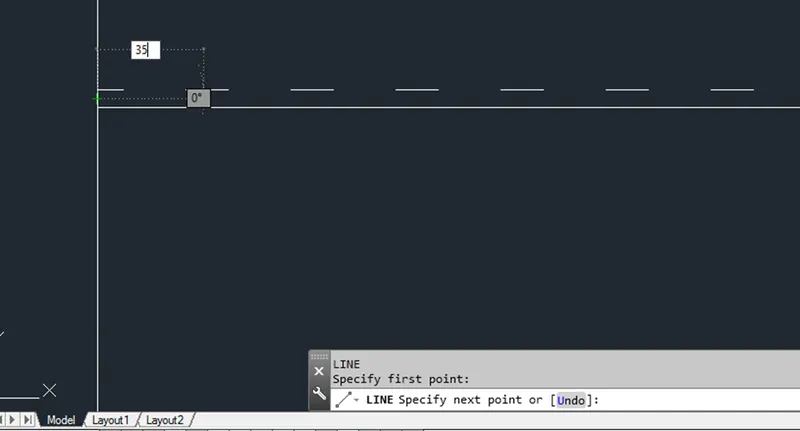
- Take a line command and draw a line of length 900mm from 35mm line
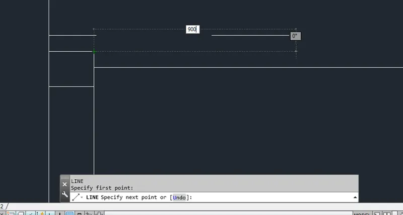
- And again take a line tool and draw a line of length 450mm from 900mm line
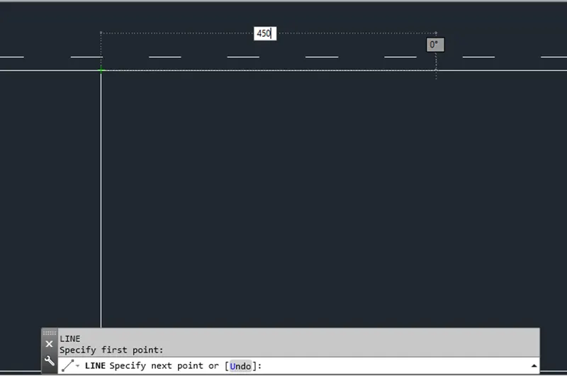
- Draw a line of 900mm length using line tool from 450mm line
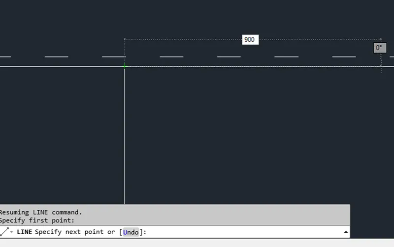
- Again draw a line of 450mm length from 900mm line using line tool
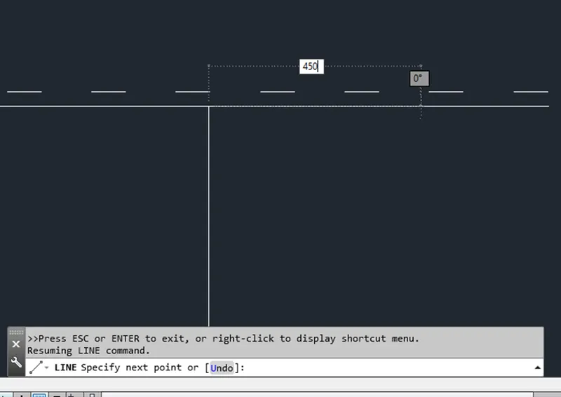
- Again draw one more line of length 450mm using line tool
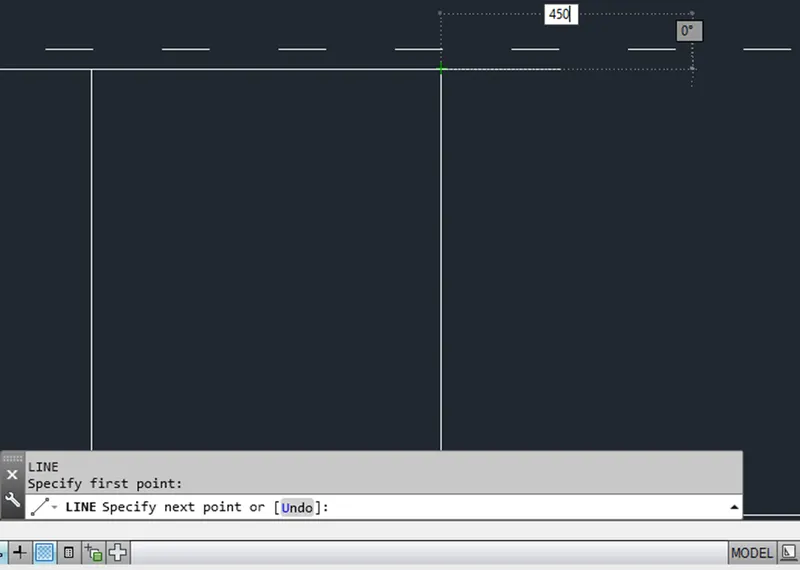
- Again draw a line of length 450mm from the 450mm line using line tool in the line command
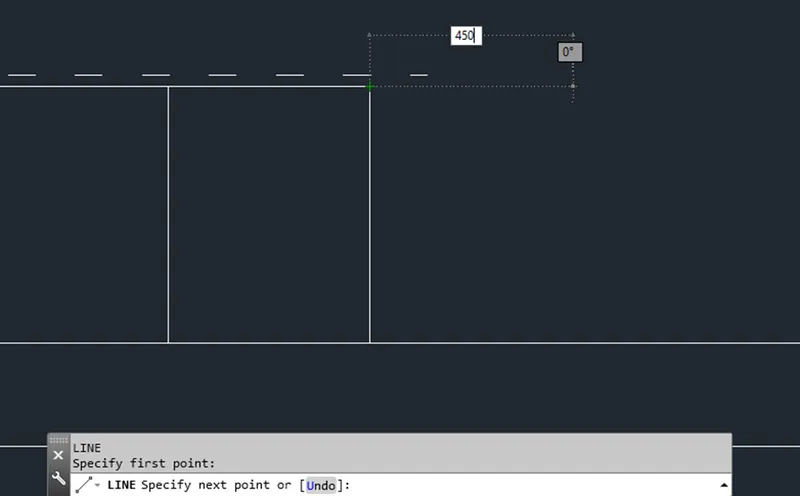
- Draw a line of length 560mm from 450mm line using line tool
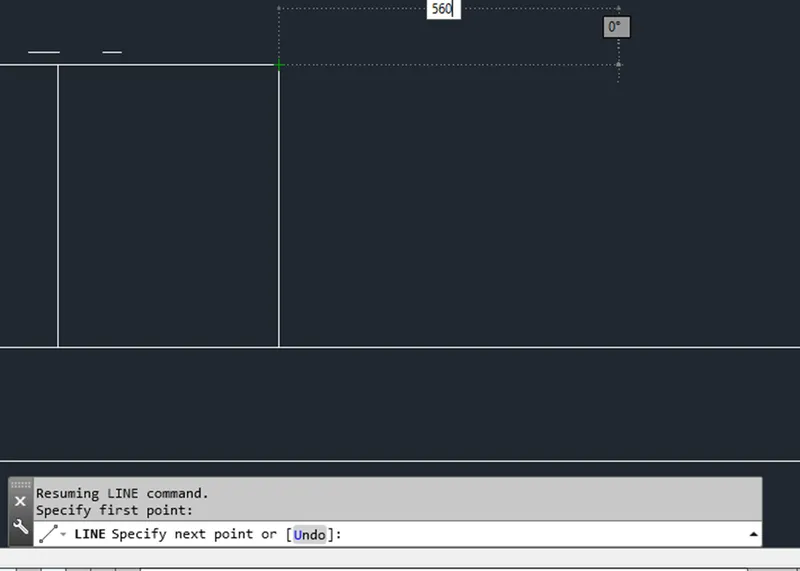
- And draw again 35mm line in the end of the 560mm line using line tool
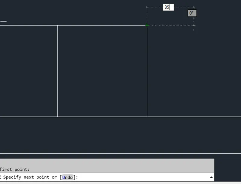
- Take offset of 25mm from the line inside using offset command
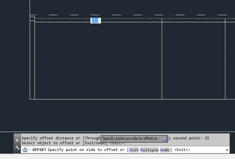
- Again take a offset of 25mm from the middle line
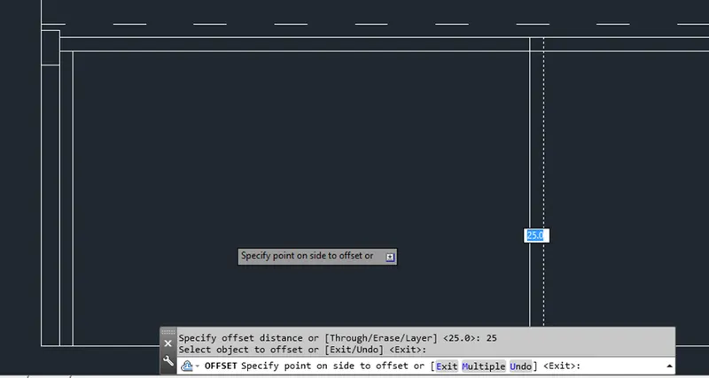
- Draw a wall in the another end using line tool
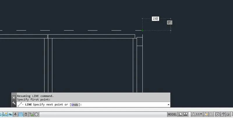
- Draw a kitchen height of 3200mm upwards using line command
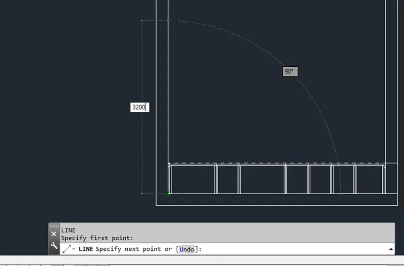
- And draw 230mm exterior wall thickness using offset command
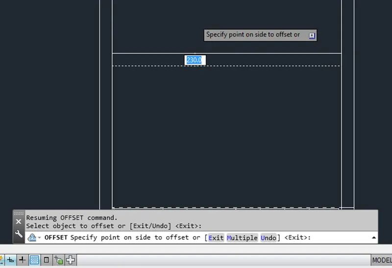
- Join these end points using line command line tool
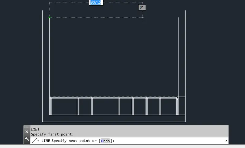
- Take 600mm offset from the line using offset command
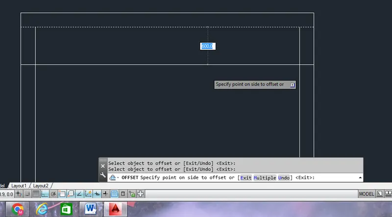
- Make this line type to Acad dash space type of line to indicate this is a reference line
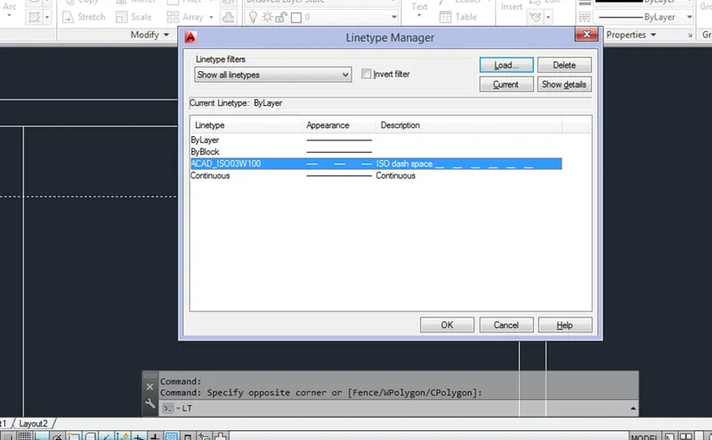
- Go to LT command and load the dash space line type and select ok
- Select the line that we want to change the line type and change the line type into the selected type of line
- Or Go to LT command in the command box and the Linetype manager dialogue box will open and select the line type that we want to change and assign the LT to the selected line and press ok
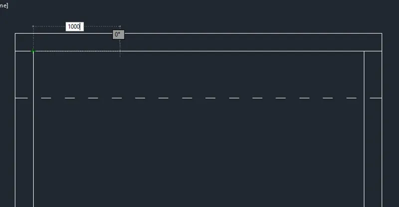
- Draw a line of length 1000mm using line tool
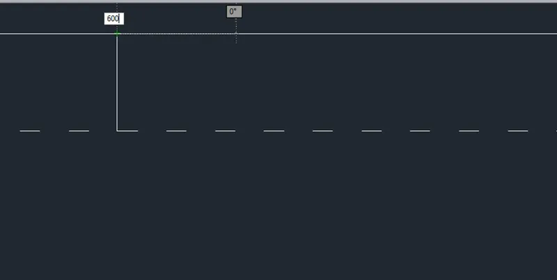
- And again draw 600mm line of length using line tool from the 1000mm line
- Go to offset command and take a offset of 450mm from 600mm line
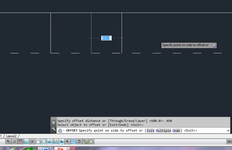
- Again take 300mm line offset from the 450mm line using offset command
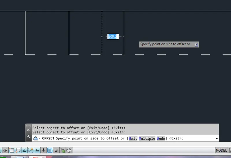
- Again take a 900mm line offset from the 300mm line using offset command
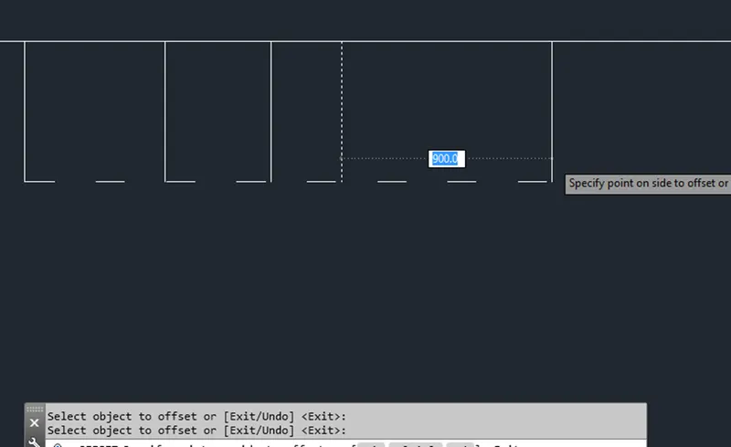
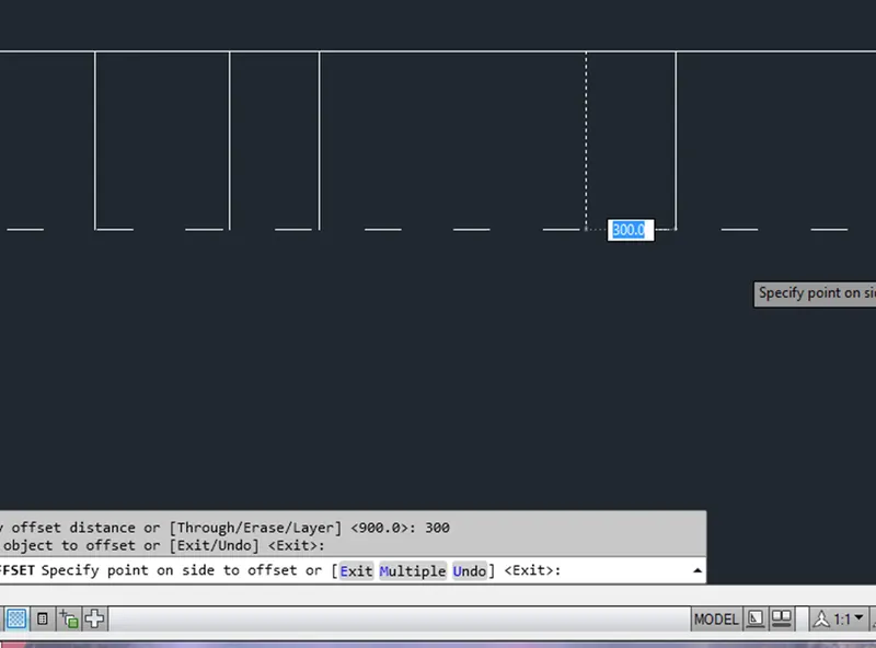
- Draw a 300mm offset line from the 900mm line using offset command
- Take offset of 25mm from the reference line using offset tool
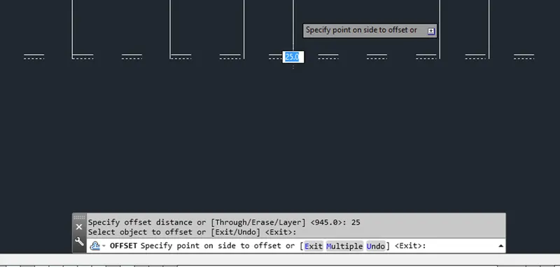
- Now create a Door D2 of required standard size of an door
- Assumne Size of the door for the kitchen is 600mm
- Take a line and draw a line of length 600mm to create a door frame
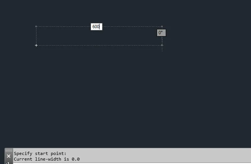
- Create two rectangle in both the ends of the line
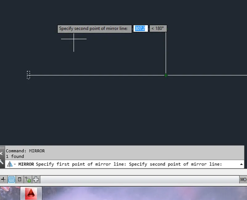
- Draw a line vertically upwards using line tool
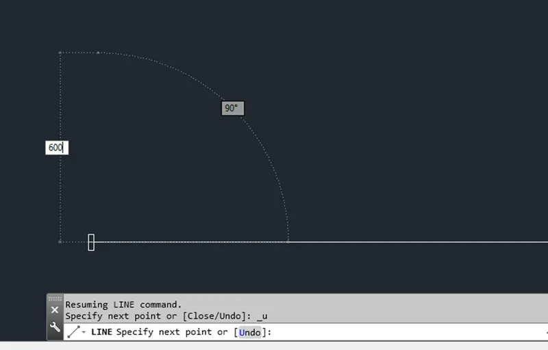
- Create a circle with both the ends reference to create a swing of a door
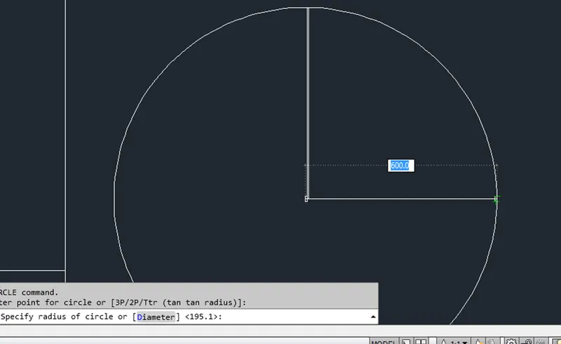
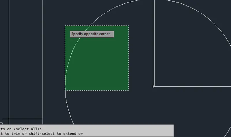
- Go to trim command and trim off the extra arcs from the circle using trim tool
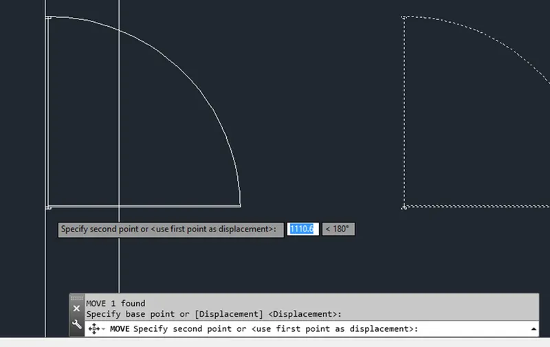
- Place the door D2 Into the kitchen plan
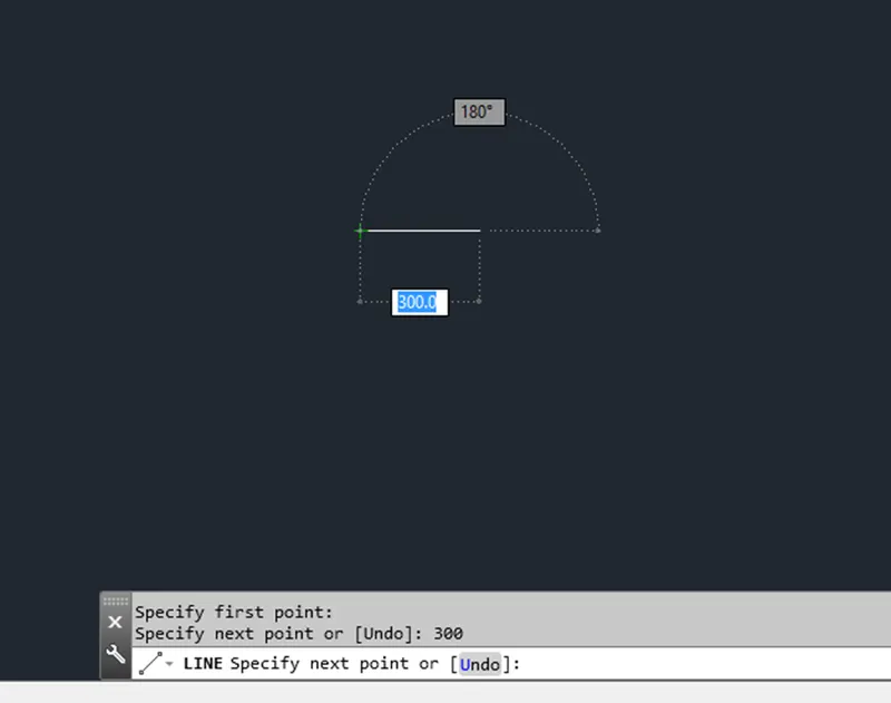
- Create a window with a standard window size using line tool
- Assumne window size as a 300mm and draw a window using a line tool
- Draw two rectangle with both the ends and place the window into the kitchen plan
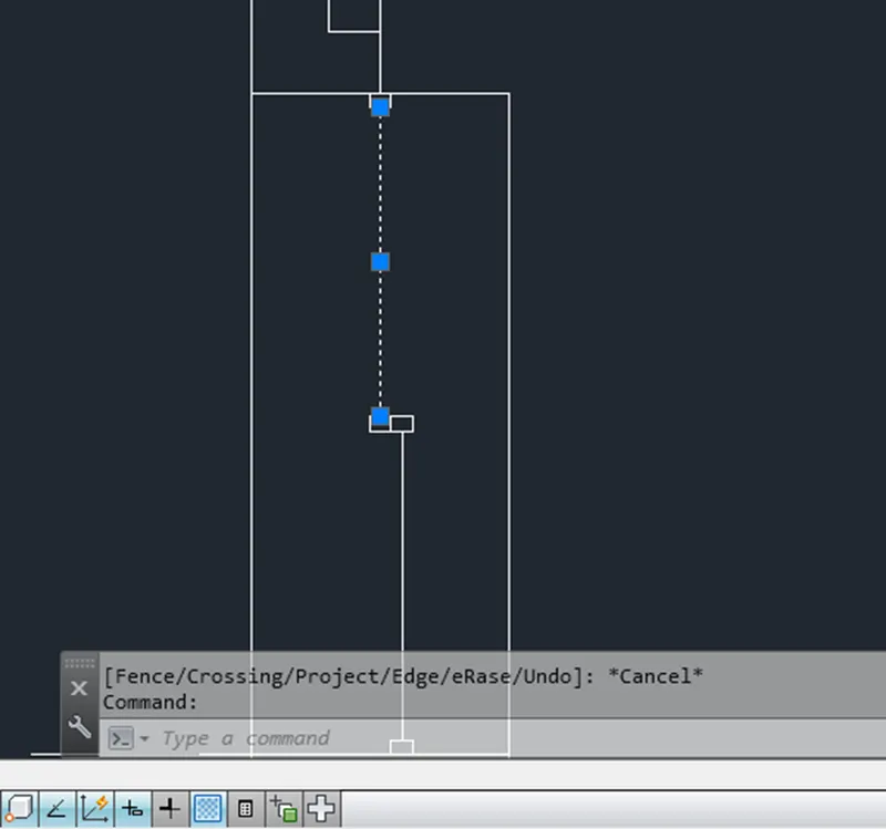
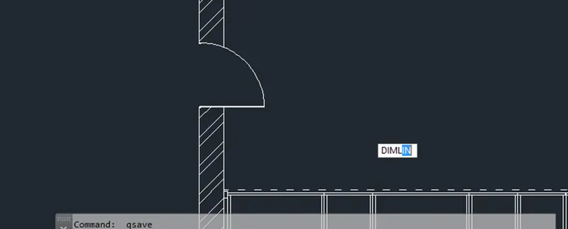
- Go to hatch command and hatch the wall layer of the kitchen by using suitable hatch type
- Type Ha in command box and hatch dialogue box will open and select the object that we want to hatch
- Select the type of hatch and press ok
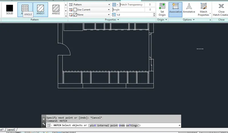
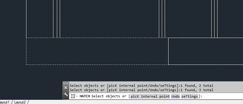
- Select the solid type of hatch and select the object that want to hatch and hatch the object
-
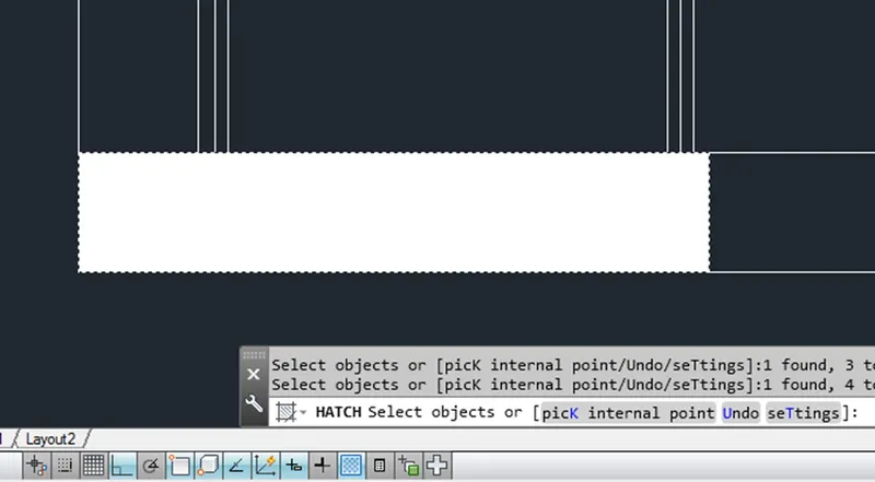
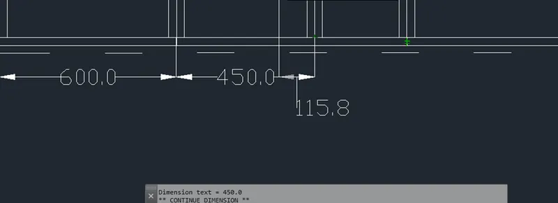
- Now dimension the kitchen layout with proper dimension techniques
- Go to dimension command and select the linear type of dimension and dimension the kitchen layout
- Dimension the kitchen layout with dimlinear dimension technique
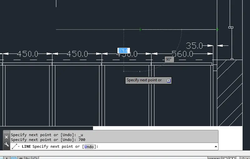
- Take 700mm line from the above point and draw a line over it using line command
- And draw 900mm line above the reference line using line command
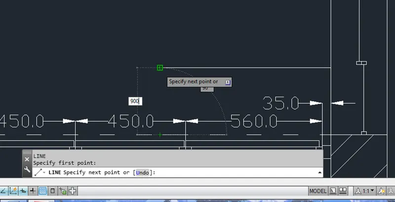
- And 600mm line in horizontal direction using line command
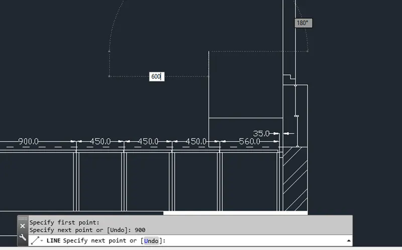
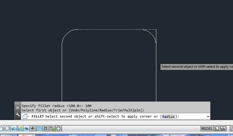
- Take a fillet of radius 1mm in the created rectangle corners edges using fillet tool
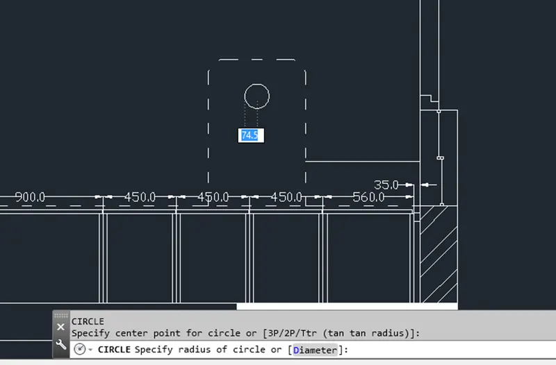
- Create a circle using circle command inside the rectangular object
- Add a text using Dtext command of height 50mm using dtext tool
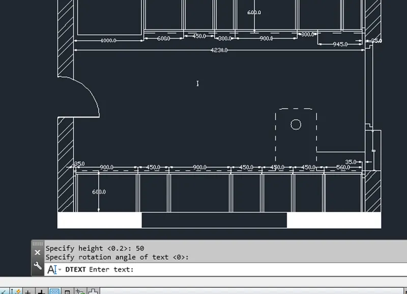
- Take a line command to draw a above counter plan layout
- Go to L line command and give a line of length 4300mm using line command in horizontal direction
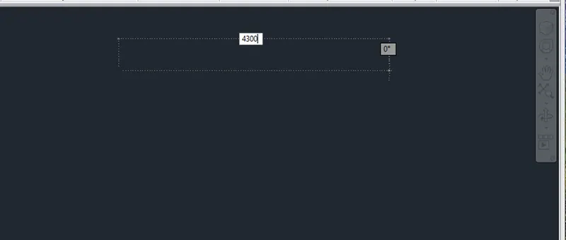
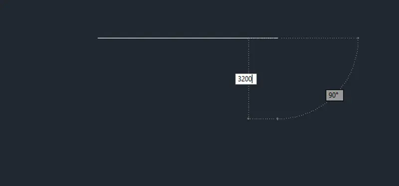
- Draw a line of height 3200mm in vertical axis using line command
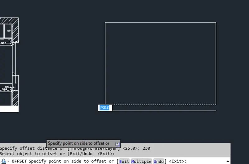
- Take a offset of 230mm outside the kitchen wall for exterior wall thickness using offset command
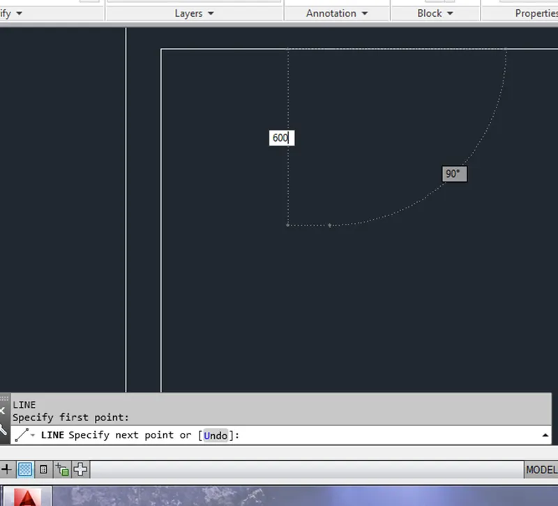
- Go to line command and draw a line of length 600mm in vertical axis
- Go to line command and draw a line of length 35mm in horizontal axis from the wall layer
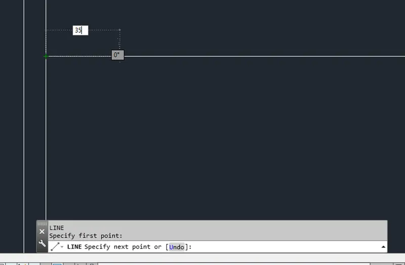
- Again take a line of length 965mm from the 35mm line using line command
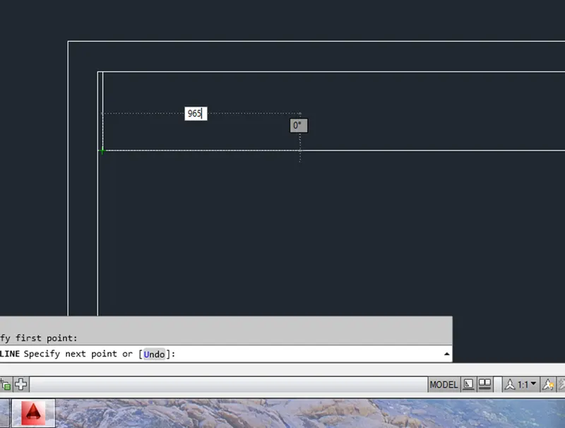
- Take 600mm line from 965mm line using line tool in line command
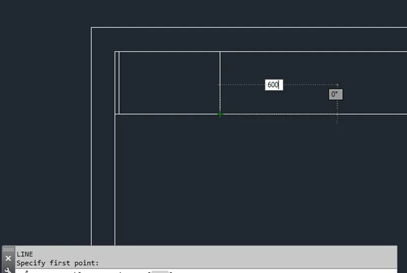
- Take a line of length 2595mm from 600mm line using line tool
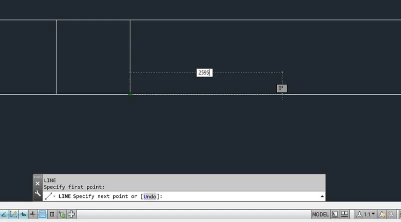
- Take a line of length 35mm from the corner end using line tool
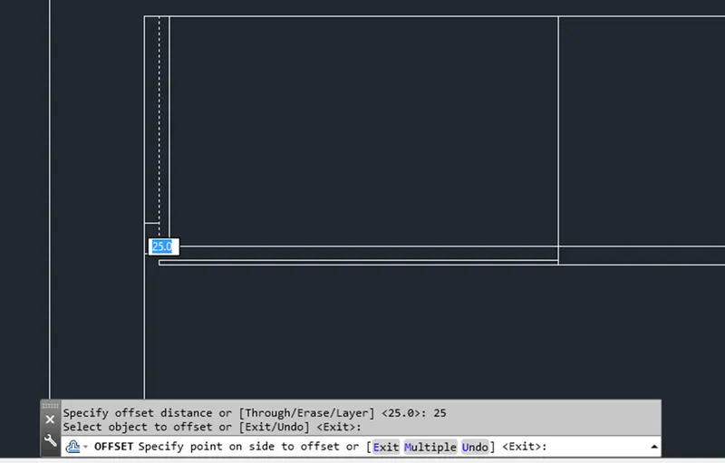
- Take offset of 25mm using offset command tool and draw a offset of length 25mm inside the walls
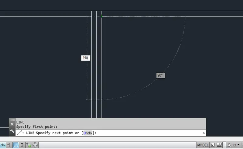
- Draw 350mm line from the wall of a kitchen using line command
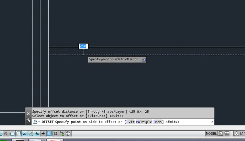
- And take offset of 25mm inside the created line
- Take a line of length 35mm using line command in the botton portion of a kitchen layout
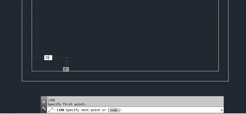
- And 350mm height inside a kitchen layout using line command
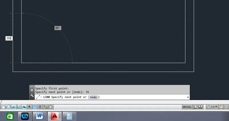
- Draw a line of length 450mm from 35mm line using line command
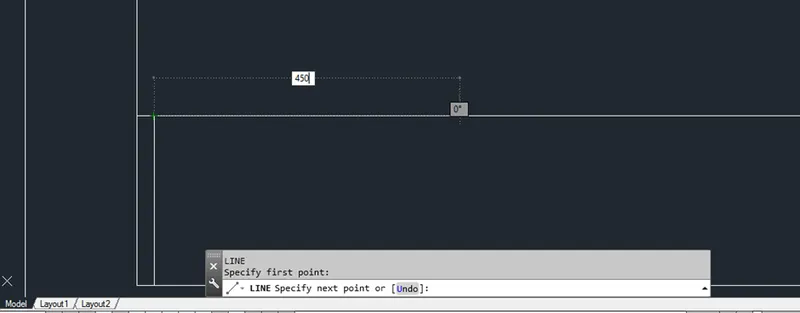
- Draw a line of length 900mm from the 450mm line using line command
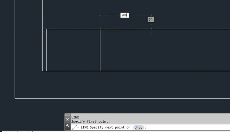
- Again draw a line of 900mm length from 900mm line using line command
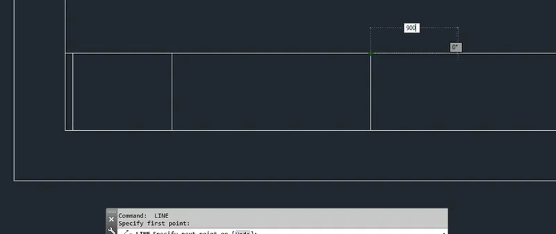
- Again take a line of length 900mm from created 900mm line using line tool
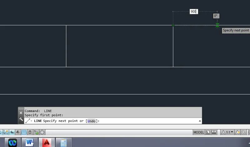
- Take a line of length 1010mm using line command from 900mm line
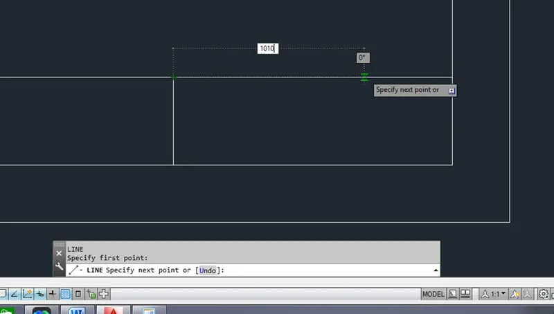
- Take a line of length 35mm using line command from 1010mm line
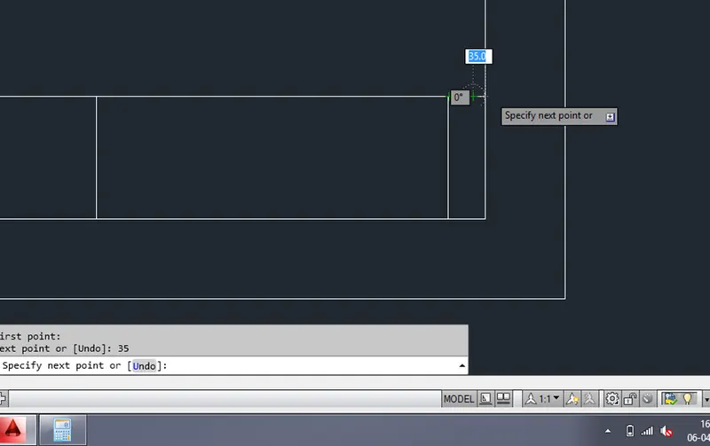
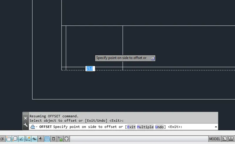
- Take a offset of length 25mm inside the kitchen layout using offset command
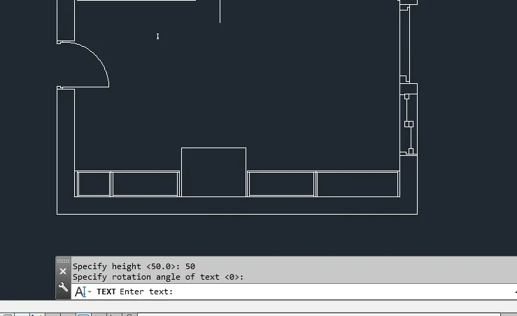
- Add a text using Dtext command to insert a text into a kitchen layout
- Go to single line text and give a height of 50mm
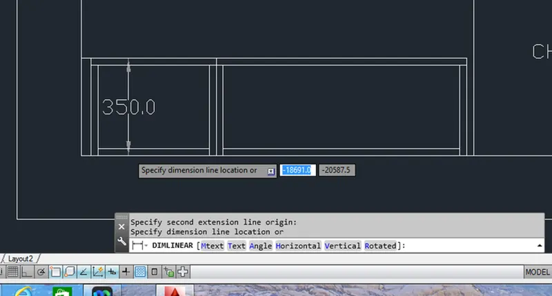
- Add dimension using dimlinear command tool to insert a dimension into a kitchen layout
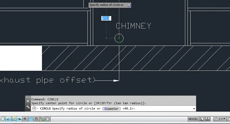
- Add a chimney at a distance of 1650mm from the wall end using circle command
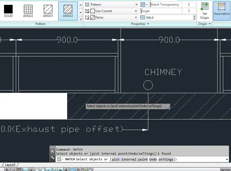
- Hatch the wall by using suitable hatch type
- Go to Ha command in command box and add the hatches to walls using hatch type
Result:
4)
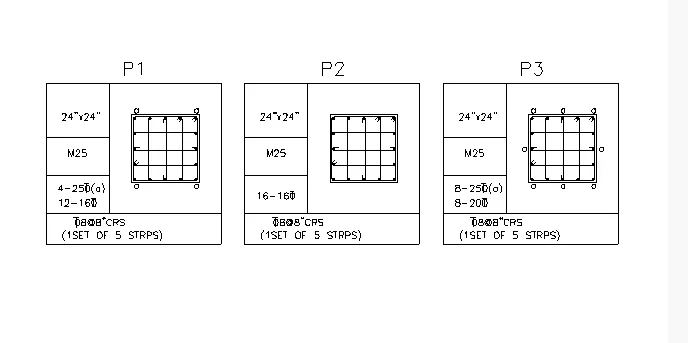
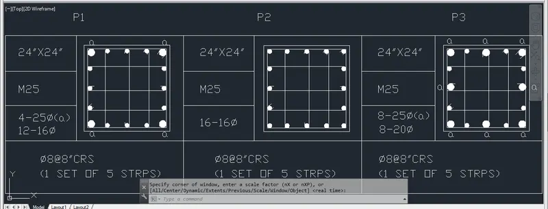
Aim: To create Column details using Autocad software
Procedure:
- Go to startmenu and open the Autocad 2014 software
- Go to startup command and give value 1 in the command box
- Set the units to engineering and precision 0'0"
- Go to units command and set the units to engineering and precision 0'0" and insertion scale as inches
- Go to limmax command and set the limits to 500
- Go to table command by giving TABLE command in command box
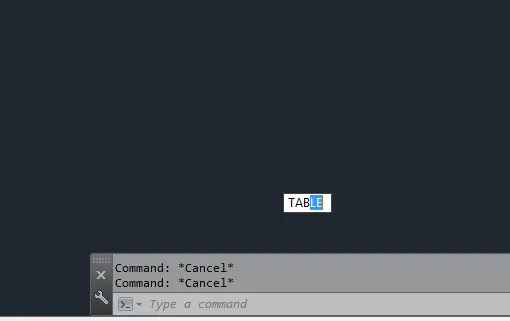
- An insert table dialouge box opens, give table style as standard, insert option as start from empty table, insertion behavior as specify insertion point and set the no of rows and columns as per our requirements and set ok
- Insert the table in the window by specifying the insertion point
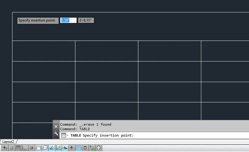
- Now create a rectangle of length 24" by 24"

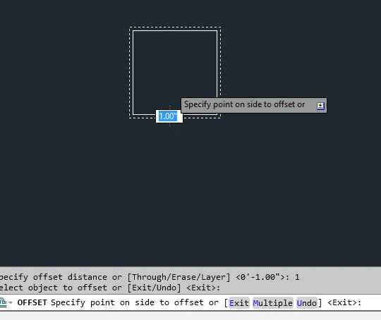
- Take a offset of 1inch inside a rectangle
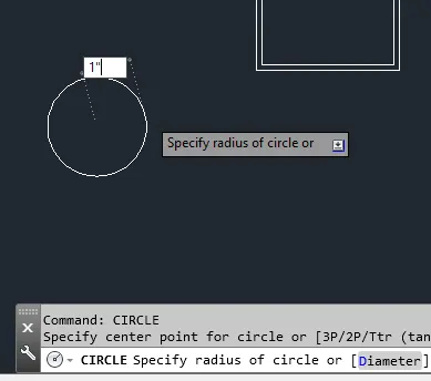
- To create a bar of 25mm dia i.e, 1inch go to circle command and draw a circle of dia 1inch
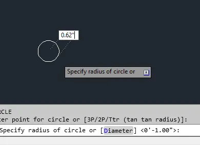
- To create a bar of dia 16mm i.e, 0.62inches go to circle command and draw a circle of dia 0.62inches
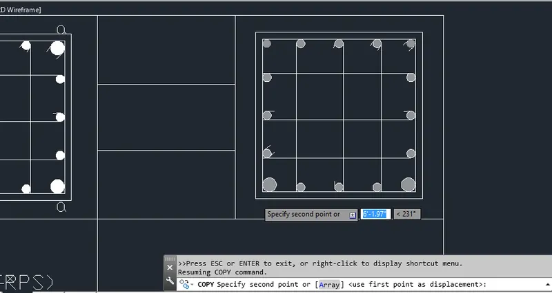
- Place the 1inch dia bars at the corners of the column using copy command
- Go to CO command in command bar and place the bars in the corner end of the column
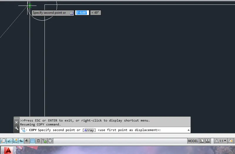
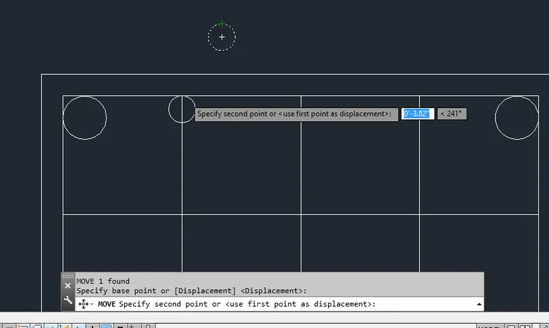
- Again place the 0.62inches dia bars in the equals intervals of a column using copy command
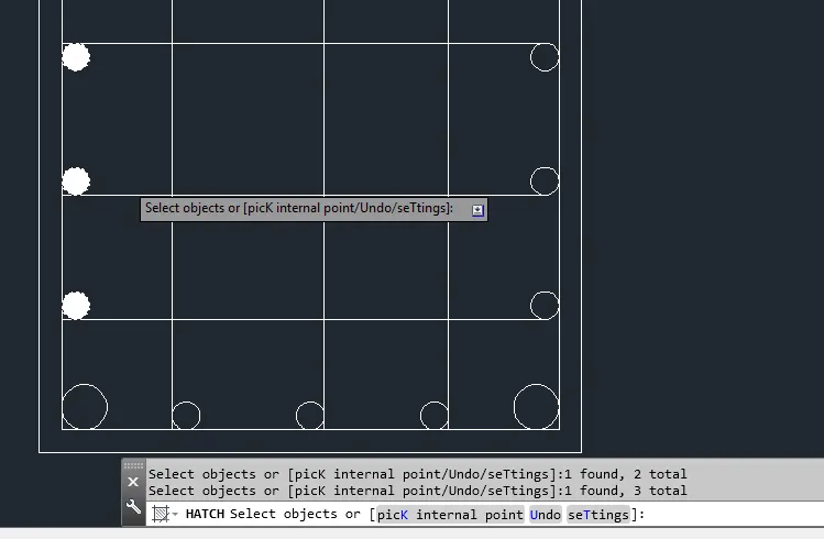
- Go to ha command and type hatch in the command box
- Select the type of hatch in the hatch option
- To hatch the bars select the solid type of hatch
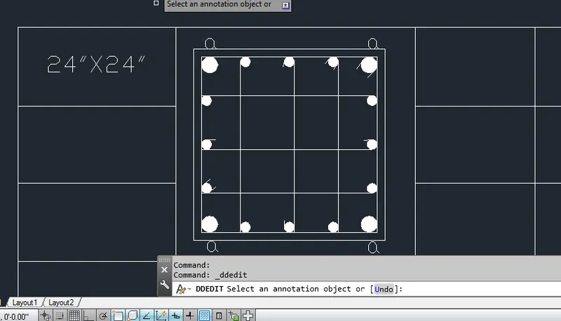
- Add text into the column detail using single line text
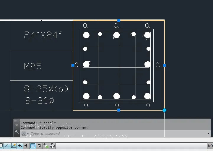
- Again add a column into the table named as P2
- Again add a P3 column into a table using move command
Result:
5)
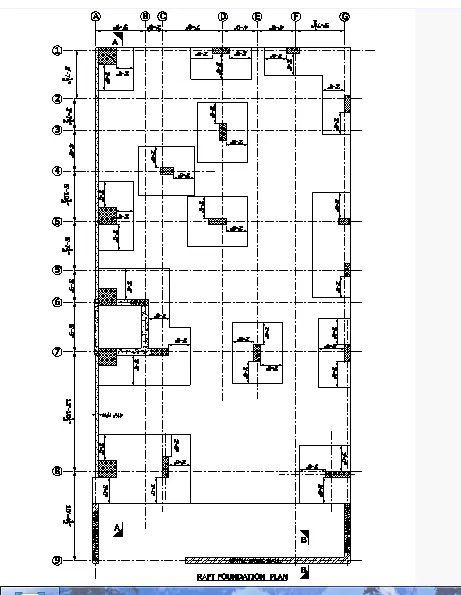
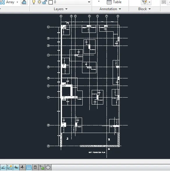
Aim: To create a given raft foundation layout by using Autocad
Procedure:
- Go to startmenu and open the Autocad 2014 software
- Go to startup command and give value 1 in the command box
- Set the units to engineering and precision 0'0"
- Go to units command and set the units to engineering and precision 0'0" and insertion scale as inches
- Go to limmax command and set the limits to 500
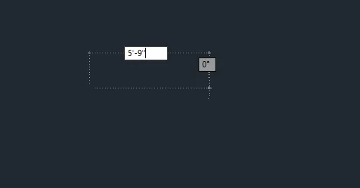
- Go to line command and draw a line of length 5'-9" using line tool
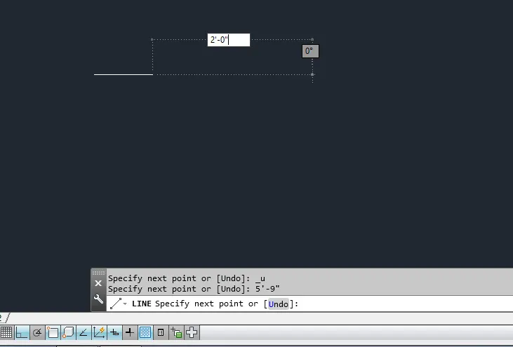
- Draw a line of length 2'-0" using line tool continue from the 5'-9" line
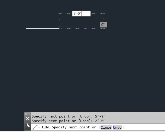
- Again draw a line of length 7'-0" using line tool continue from 2' line
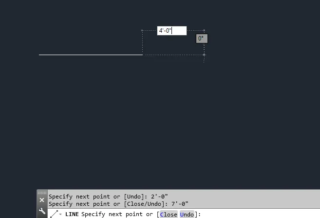
- Again draw a line of length 4'-0" usinng line tool continue from the 7' line
- Draw a line of length 4'-6" using line tool continue fro the 4' line
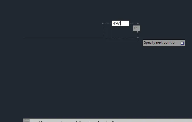
- Again draw a line of length 5'-7.5" using line tool continue from the 4'-6" line
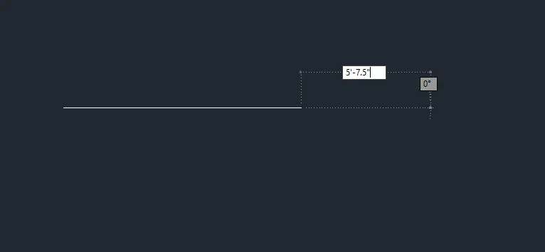
- Again draw a line of length 5'-7.5" in the negative vertical axis using line tool
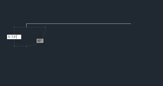
- Draw a line of length 3'-7.5" using line tool from 5'-7.5" line
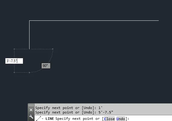
- Draw a line of length 4'-9" from the 3'-7.5" line using line command
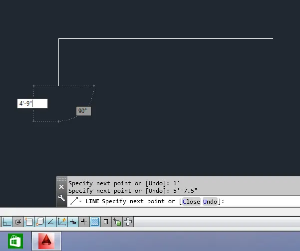
- Draw a line of length 5'-10.5" using line command from 4'-9" line
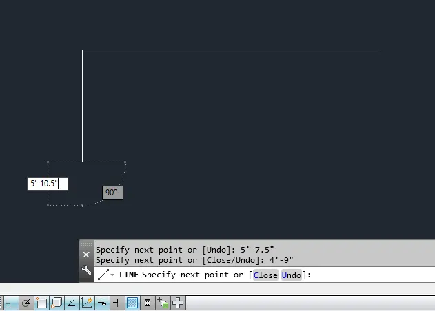
- Draw a line of length 5'-7.5" using line tool from 5'10.5" line
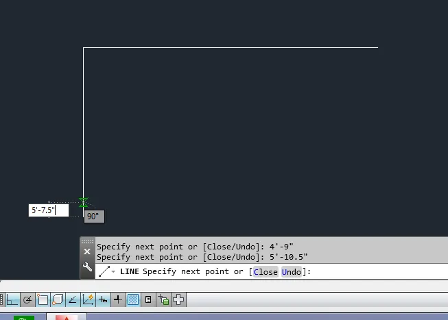
- Draw a line of length 3'-9" using line toolfrom 5'-7.5" line
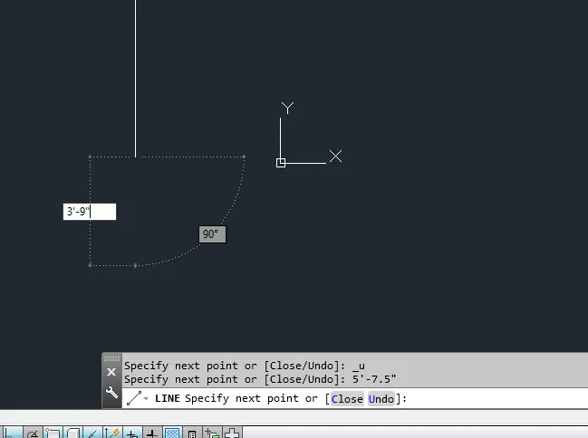
- Draw a line of length 5'-9" using line tool from 3'-9" line
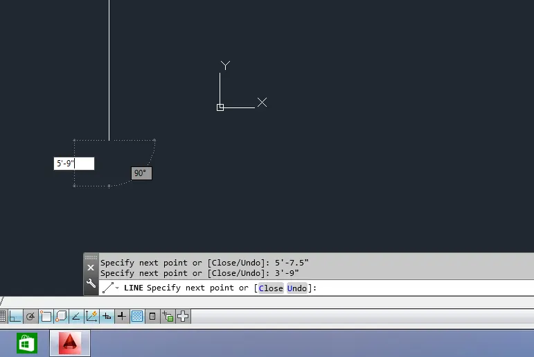
- Draw a line of length 13'-10.5" using line tool from 5'-9" line
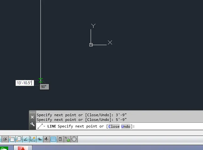
- Again draw a line of length 10'-4.5" using line tool from 13'-10.5" line
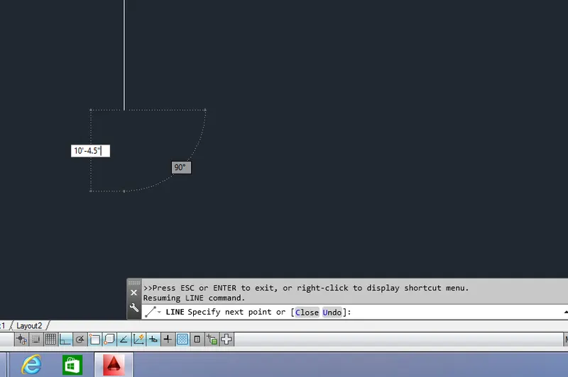
- Now add a line to the measured dimensions
- Go to LT command in command box and load the ISO long dash and short dash type of line
- Draw a line to measured dimensions and change the line type into a lond dash and short dash type of line
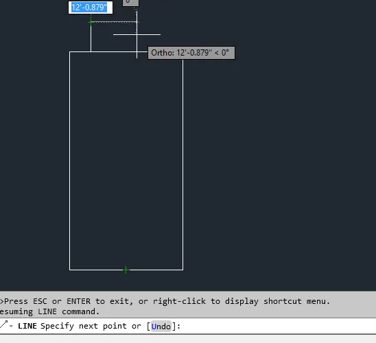
- Now after adding a reference lines add a column of size 24"X24"
- Go to rectangle command and draw a rectangle of size 24"X24"
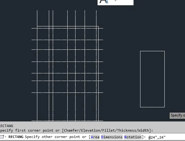
- Place the column inside the footing
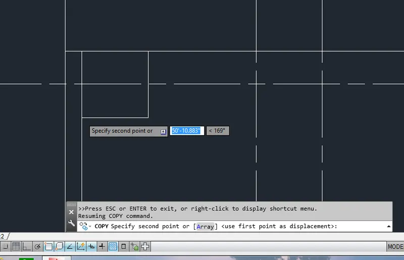
- Draw a footing of size 2'X3' usig line command
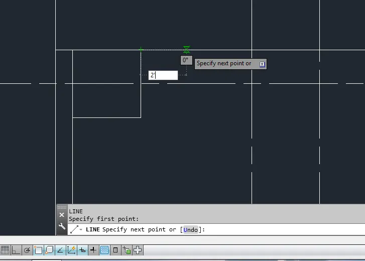
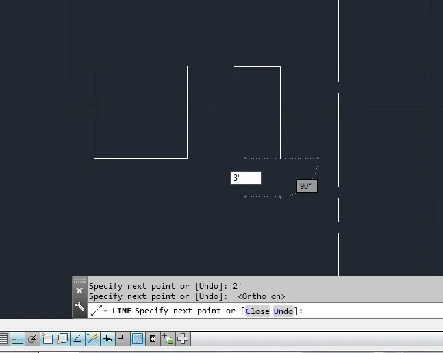
- To insert a column C2 go to rectangle command and draw a column of size 9"X24" using rectangle command
- Place the column C2 inside the footing
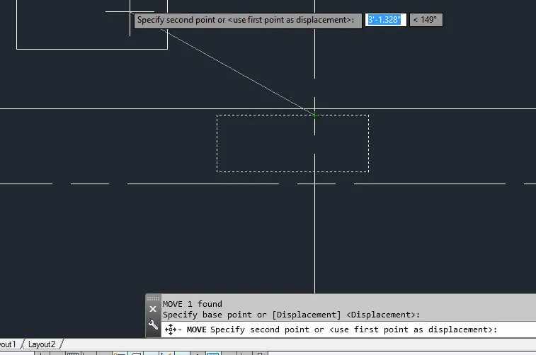
- Draw a footing of size 2'-6" on either side of the column using line tool
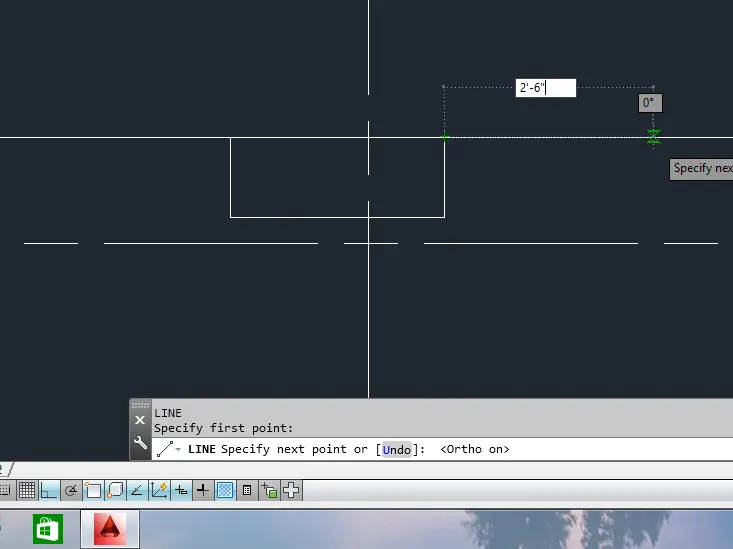
- Draw a footing width of size 3'-0" using line tool
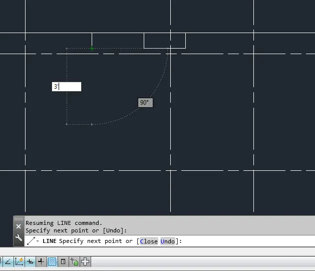
- Also insert a column of size 9"X18" using rectangle command
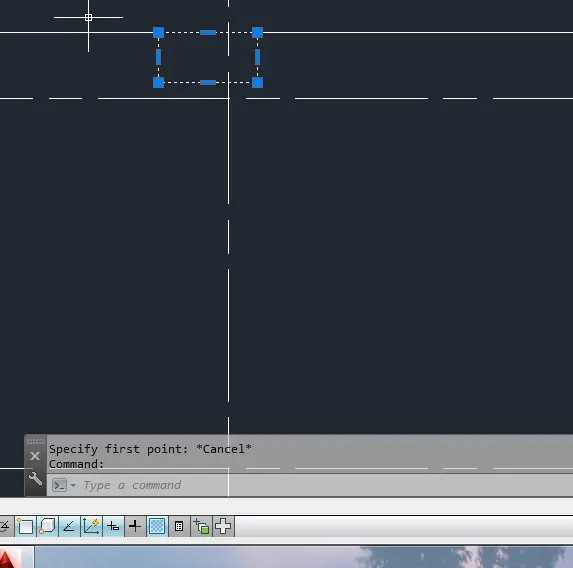
- And insert a footing of size 2-6"X 2'-6" using line tool
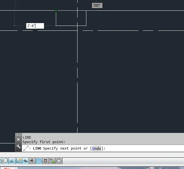
- Also place the column C2 in the another place of foundation
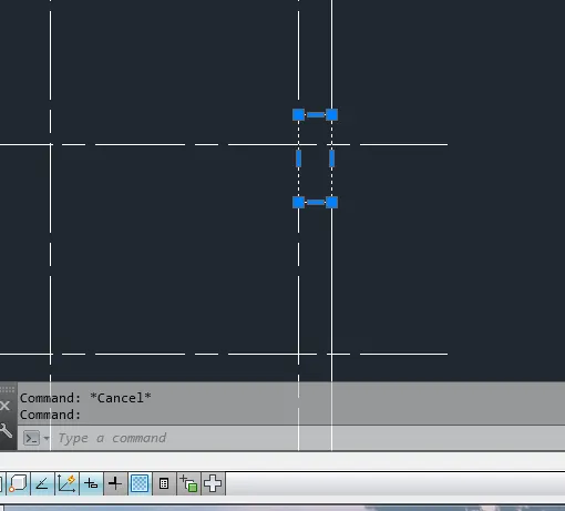
- And insert a footing of size 2'-6" using line command
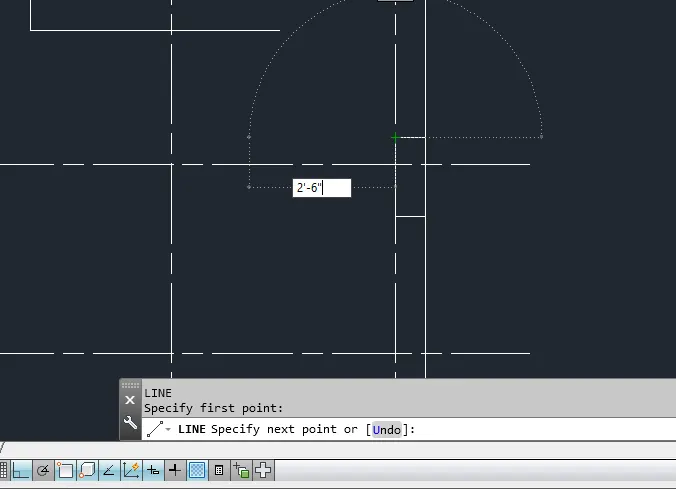
- And also place a column C2 in another position using move command
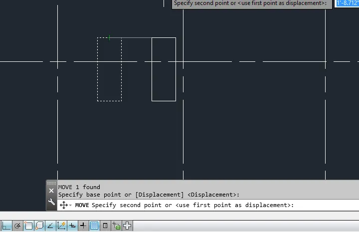
- Also draw a footing of size 2'-6" using line command
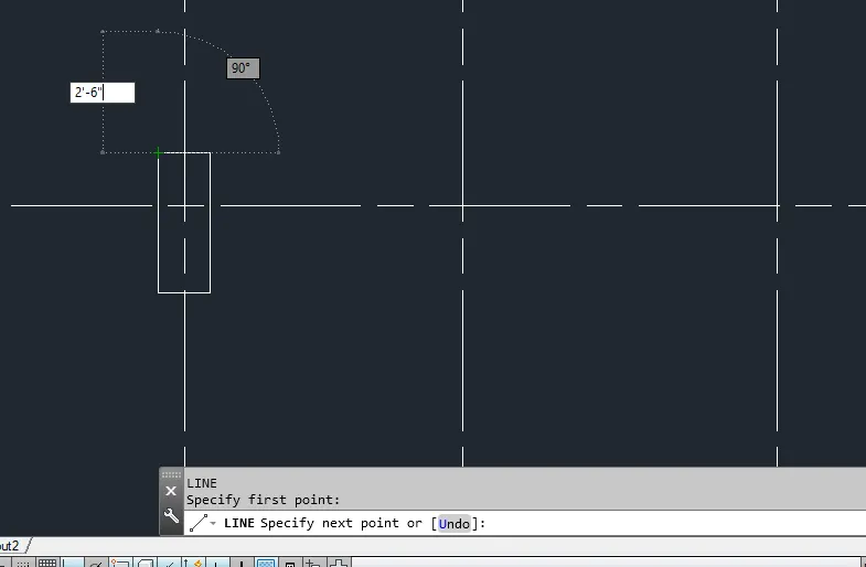
- Also place column C3 using move command in another place
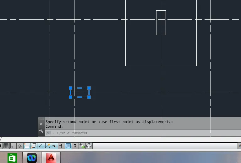
- And add a footing to the column C3 using line command
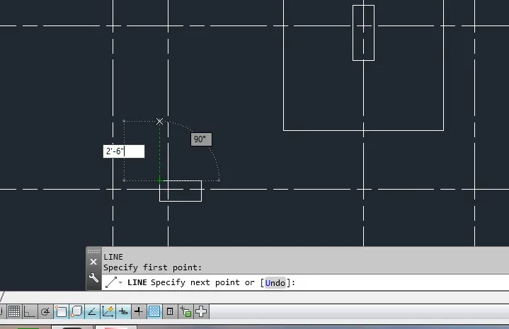
- Place the column C1 in the another place inside a plan
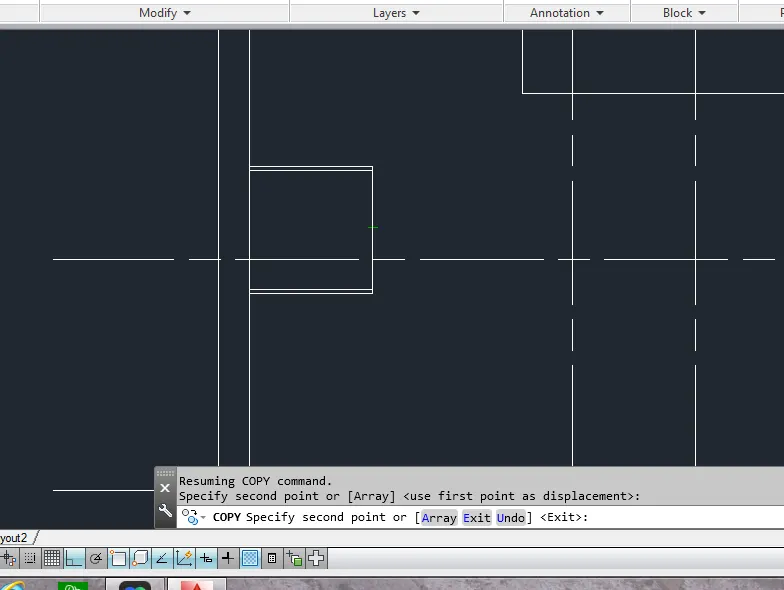
- And add a footing of size 2'X3' using line command
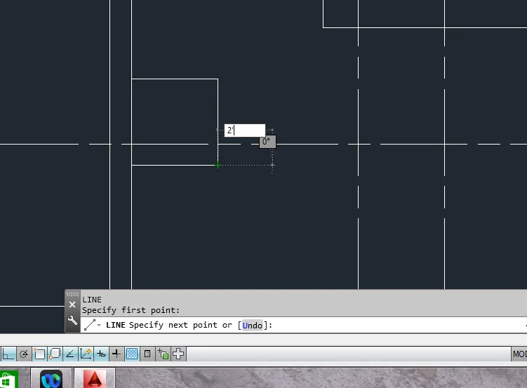
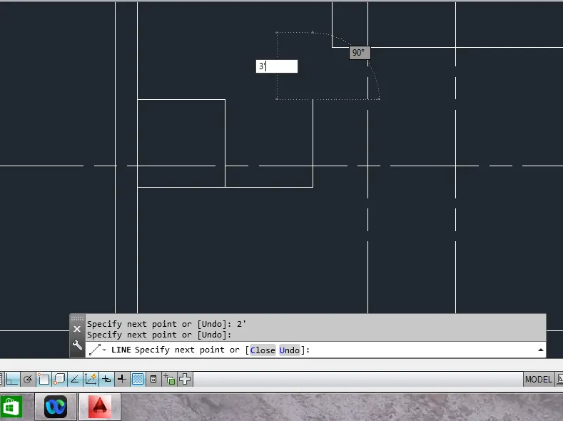
- Create a column of size 9"X24" and named it as C4 using rectangle command
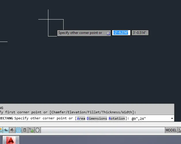
- And add a footing of size 2'-6" using line command
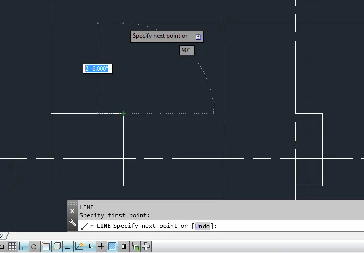
- And again place a column C4 in another position using move command
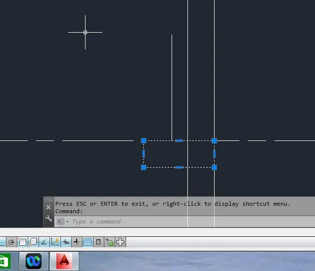
- Add a footing of size 3' and 3' in the either side of the column using line command
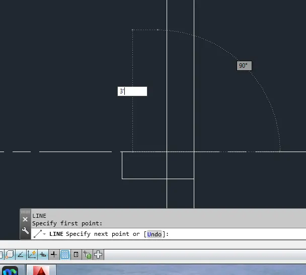
- Draw a 9" thick brick wall using line command
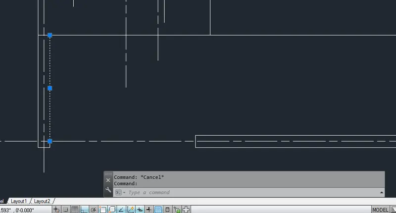
- Go to Ha command and select the ANSI32 type of hatch using hatch command
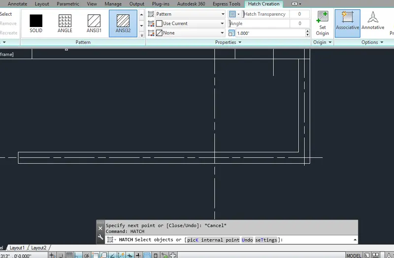
- Select the objects to hatch by clicking on that object
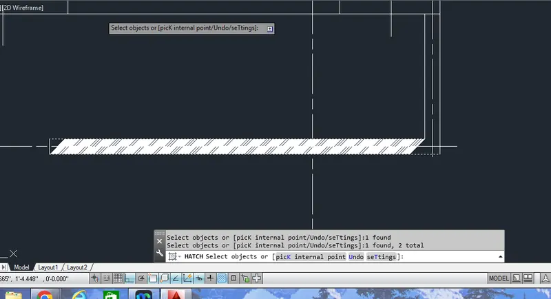
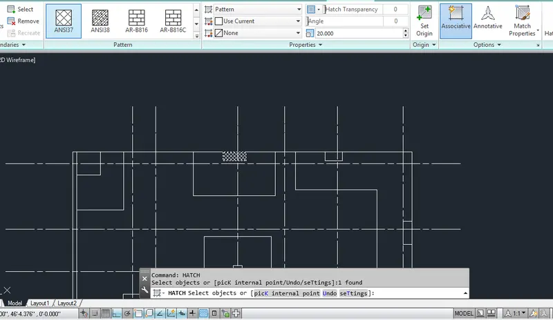
- Again select the ANSI37 type of hatch to hatch the column object
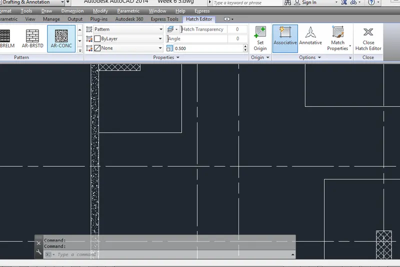
- Again select the concrete AR-conc tye of hatch to hatch the wall surface using hatch command
- Now name the raft foundation using single line text command and place the text inside the layout
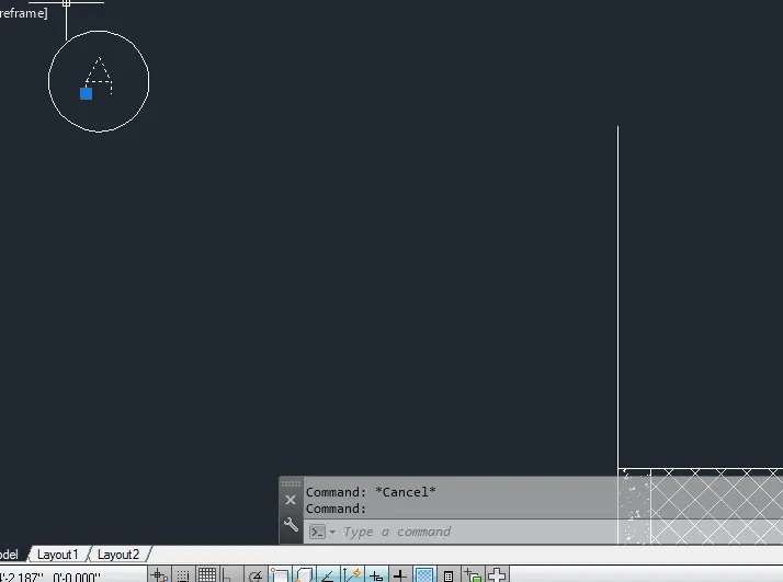
- Firstly create a circle and add a text inside a circle using single line text
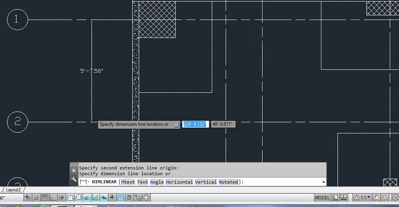
- Finally go to dimension and add a dimension into a layout
- Go to dimlinear option and add a dimensions using dimlinear option
Result:
1