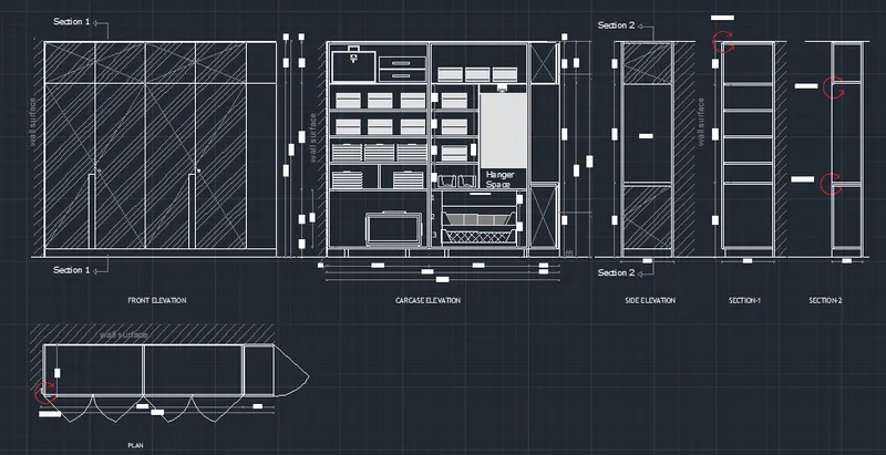
Creating a Wardrobe detailed drawing, Floor Plan, Kitchen Layout and Column Detail using AutoCad
1 The elevation and details of a wardrobe.
AIM :
To Draw the elevation and details of a wardrobe using AutoCAD software
INTRODUCTION
This type of drawing can be drawn by using the line command or rectangle command with specifying the length and angle of the drawing
PROCEDURE
• Open AutoCAD software
• Choose the imperial template and start from scratch
• Set the units to engineering and select ok
• Choose line command by pressing 'L' enter and to give the dimensions to the command, the line was drawn.
• Indicate the direction of the line by the keeping ortho mode is ON . Give the line measurement as per given in drawing as question
• After completion of drawing exit from line command and starting giving dimensions
• To give dimensions enter DIM Dimension and select the line to locate the dimension in object
• To set the properties of dimension enter DIMS' (Dimension style) and specity the sizes as per requirements
• To save the file go to the AutoCAD application and choose the same as option
• Now select the snipping tool to take screenshot
RESULT
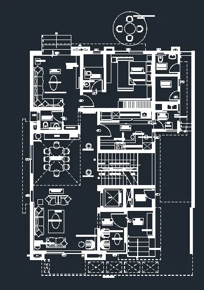
2. Draw the floor plan
AIM :
To Draw the floor plan using AutoCAD software
INTRODUCTION
This type of drawing can be drawn by using the line command or rectangle command with specifying the length and angle of the drawing
PROCEDURE
• Open AutoCAD software
• Choose the imperial template and start from scratch
• Set the units to engineering and select ok
• Choose line command by pressing 'L' enter and to give the dimensions to the command, the line was drawn.
• Indicate the direction of the line by the keeping ortho mode is ON . Give the line measurement as per given in drawing as question
• After completion of drawing exit from line command and starting giving dimensions
• To give dimensions enter DIM Dimension and select the line to locate the dimension in object
• To set the properties of dimension enter DIMS' (Dimension style) and specity the sizes as per requirements
• To save the file go to the AutoCAD application and choose the same as option
• Now select the snipping tool to take screenshot
RESULT
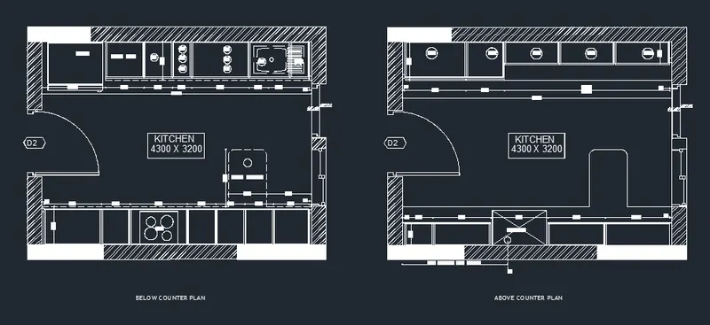
3. Create the Kitchen Layout
AIM :
To Draw the kitchen layout using AutoCAD software
INTRODUCTION
This type of drawing can be drawn by using the line command or rectangle command with specifying the length and angle of the drawing
PROCEDURE
• Open AutoCAD software
• Choose the imperial template and start from scratch
• Set the units to engineering and select ok
• Choose line command by pressing 'L' enter and to give the dimensions to the command, the line was drawn.
• Indicate the direction of the line by the keeping ortho mode is ON . Give the line measurement as per given in drawing as question
• After completion of drawing exit from line command and starting giving dimensions
• To give dimensions enter DIM Dimension and select the line to locate the dimension in object
• To set the properties of dimension enter DIMS' (Dimension style) and specity the sizes as per requirements
• To save the file go to the AutoCAD application and choose the same as option
• Now select the snipping tool to take screenshot
RESULT
4. Sketch the column details
Aim
Create a column schedule as shown in the figure using AutoCAD
INTRODUCTION
This type of drawing can be drawn by using the line, text, rectangle command with specifying the length and angle of the drawing given in figure
PROCEDURE
- Open the AutoCAD software and dick on new for a new drawing she.
- Enter units in command box
- Select Engineering in type 0-0.0" in precision and inches in units to scale inserted content Press OK
- Ensure the dynamic input is off
- Choose line command by pressing 'I: enter and to give the dimensions to the command, the line was drawn.
- Take the offset of this line of 24"
- Again L-enter and join both the ends on each side
- Take the offset of vertical line give value 9"
- Take the offset 6 times
- Take offset now select horizontal line and give value 5 and do the offset 3 times
- enter the text by selecting text then select font that is given in the question select the base point and then give the height here i have given 8" then give the angle here i have given 0 degree and 90 degrees
- enter the text in every recommended place by following the above steps
- To save the file, go to the AutoCAD application and choose the save as option
- Now select the snapping tool to take screenshot
RESULT
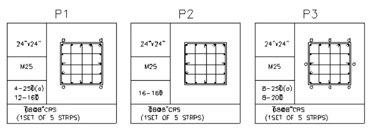
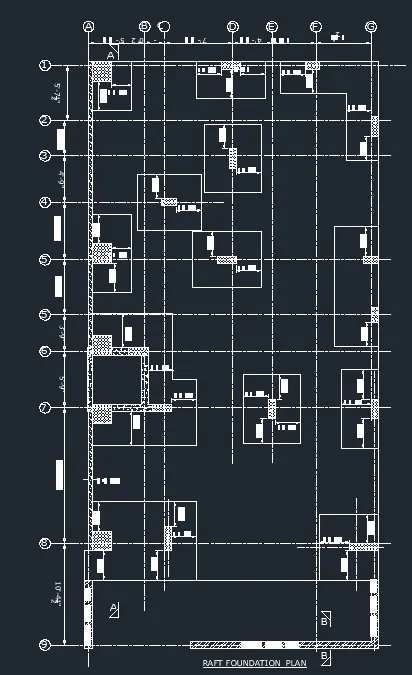
5. Draw the Raft Layout
Aim
Create the raft layout details as shown in the figure and proving the text wherever given using AutoCAD
INTRODUCTION
This type of drawing can be drawn by using the line, rectangle, hatch, text command with specifying the number of rows and column as given in figure
PROCEDURE
- Open the AutoCAD software and dick on new for a new drawing sheet
- Enter units in command box
- Select Engineering in type 0-0.0" in precision and inches in units to scale inserted content Press OK
- Ensure the dynamic input is off
- Choose line command by pressing enter and to give the dimensions to the command, the line was drawn
- select offset put value 3 and offset the horizontal line
- select offset enter value Tand offset two times
- select trim option and trim all the unwanted lines
- In the upper and lower box make a line and offset till the box gets filled and trim the unwanted lines
- Select text from the upper tab and select single line
- Select multileader command to give the text with arrow
- To save the file, go to the AutoCAD application and choose the save as option
- Now select the snapping tool to take screenshot
RESULT