Creating a Wardrobe detailed drawing, Floor Plan, Kitchen Layout and Column Detail using AutoCad
AIM:
Creating a Wardrobe Detailed Drawing, Floor Plan, Kitchen Layout and Column Detail using AutoCAD.
OBJECTIVE:
To draw the given sketch of Elevation & details of a Wardrobe,
Floor Plan,
Kitchen layout
Column details
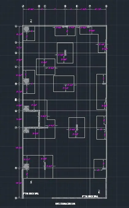
Raft Foundation detail using AutoCAD.
INTRODUCTION:
- Creating the given Elevation & details of wardrobe using decimal units i.e., in millimeters
Sketch the given drawing, adding the different layers, dimension & annotation it.
- Creating the given floor plan using decimal units i.e., in millimeters
Sketch the given drawing, adding the different layers, dimension & annotation it.
- Creating the given Kitchen Layout using decimal units i.e., in millimeters
Sketch the given drawing, adding the different layers, dimension & annotation it.
- Creating the given Column Reinforcement detail using decimal units i.e., in millimeters
Sketch the given drawing, adding the different layers, dimension & annotation it.
- Creating the given Raft Foundation details of wardrobe using decimal units i.e., in millimeters
Sketch the given drawing, adding the different layers, dimension & annotation it.
Commands used:
Polyline/Line, Multi-text/Text, Donuts, Offset, Extend, Fillet, Mirror, Trim, Move, Rotate, Annotate.
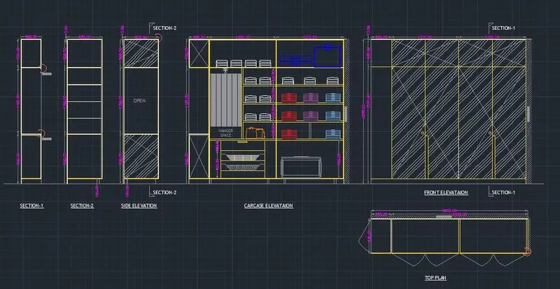
1). WARDROBE ELEVATION
PROCEDURE
Step-1: New Sheet-Units-Decimal-precision 0.0 millimeter & OK.
Step-2: First using command: REC Rectangle > 2800, 2600
Command: O Offset, from the top of dimensions 12 & 488 mm
Step-3: Create offset from the side at the distance of 608.75 & 365
Step-4: command: L by increasing the transparency to create wall surface
Using hatch give the hatch & give scale accordingly.
Command: Q leader to mention the annotations
Step-5: Command: REC Rectangle > 630 x 2800
Command: Q leader to mention the annotations
Step-6: Command: REC Rectangle > 2800 x 2600
With the help of line command drawers & cabinets are created
Dimension the drawing
Step-7: Command: REC Rectangle > 520 x 630, 1180 x 630, 900 x 630 & this is repeated two times.
Command: L the next of the lines are drawn
Step-8: Place the entire drawing in the respective layers.
Step-9: Command: DLI Dim linear
Select object/walls to dimension as shown in sketch.
2). FLOOR PLAN:
PROCEDURE
Step-1: New Sheet-Units-Decimal-precision 0.0 millimeter & OK.
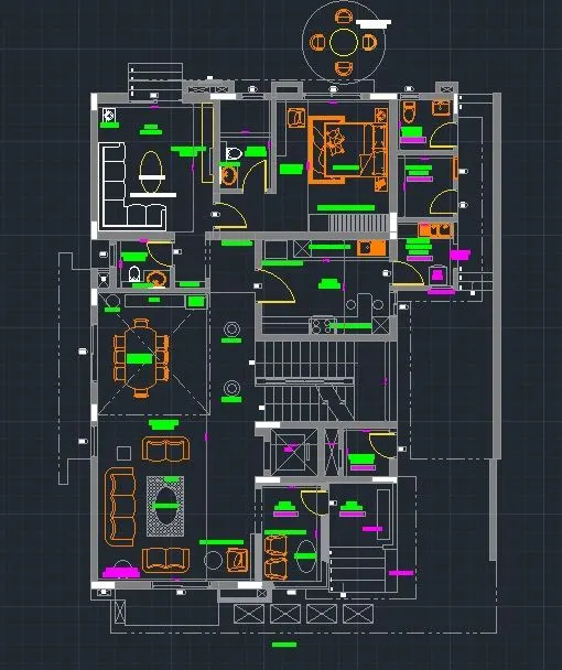
Step-2: Command: XL to draw the infinite lines i.e., Horizontal & Vertical.
Command: O Offset, to offset the line for particular distance
Command: ARC, doors are also created.
Step-3: To draw a canopy circle> In the main bar click on circle > Centre, radius
Specify the Centre point as 10,0 & radius 452
In the main bar click on circle > Centre, radius
Specify the Centre points same as the previous circle (10,0) & radius 1398
Creating circles:
Draw a circle with a command: C select a center point & give the radius as 1398mm
Draw another circle with same center point with radius 452mm.
Draw an offset of 200 mm from the inner circle to determine the position of chairs
Draw lines along the diameter of the bigger circle.
Drawing chairs:
Draw a rectangle command: REC giving dimensions as 400mm & 200mm
Draw an arc with start-center end method with the end point & center of the side(400mm) of rectangle
Draw another rectangle of 55mm x 100mm for the handle of the chair command: REC- select the base point & click dimension & give as 55mm & 100mm
Copy it to other side so that both handles are formed.
Fillet the corner of rectangle by 50mm command: O- give the fillet radius as 50mm & select the two lines & trim off the unwanted line.
Move the chair & place it such a way that it touches the offset 200mm circle. By using command: M- select the base point & move it.
Mirror the chair to the opposite side, command: MI
Rotate the chair & move it so that the chair in left side is created command: RO- select the base point, mirror the chair so as to create chair in right side.
Step-4: Give the dimensions & Annotation the drawing with the text where ever required.
Step-5: Place the entire drawing in the respective layers.
Step-6: Command: DLI Dim linear
Select object/walls to dimension as shown in sketch.
3). KITCHEN LAYOUT:
PROCEDURE
Step-1: New Sheet-Units-Decimal-precision 0.0 millimeter & OK.
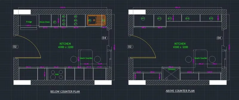
Step-2: Command: REC Rectangle & dimensions are 4734 x 3688 mm.
Command: O Offset, offset it to the distance of 250 mm.
Using Arc & lines the door is drawn.
Using hatch command hatch the model.
Step-3: Command: REC Rectangle > dimensions, to do the fridge Step-3: Command: REC Rectangle > dimensions, to do the fridge.
Command: O Offset, offset it to the desired distance to get the Micro Oven.
Command: T Trim to trim the extras.
Command: O Offset, & offset it to the horizontal distance of 350, 450, 900, 450 & 560.
Command: T Trim to trim the extras.
Command: L Line type & load the dotted lines.
Step-4: command: T Text to text the given annotations
Command: DLI Dim linear is used to name the dimensions.
Step-5: Place the all elements of the drawing in the respective layers
4). COLUMN DETAILS:
PROCEDURE
Step-1: New Sheet-Units-Decimal-precision 0.0 millimeter & OK.
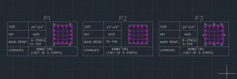
Step-2: Using Command: Rectangle & Line the tables are drawn.
Step-3: Using Command: T Text is given.
Step-4: Command: L Lines to draw the reinforcement.
Command: Donuts the reinforcement circles to be drawn.
5). RAFT FOUNDATION LAYOUT:
PROCEDURE
Step-1: New Sheet-Units-Engineering--precision 0’.0’’ feet & OK.
Step-2: Command: XL to draw the infinite lines i.e., Horizontal & Vertical.
Command: O Offset, to offset the line for particular distance
Step-3: Command: REC Rectangle > dimensions are 29’ 7’’ & 60’
To get dotted lines click on line type & load the dotted lines > set current.
With the help of dotted lines & offset command the grids are drawn
Step-4: Command: O Offset the distance to 4’’
The ribbon > hatch > AR-CONC
Command: REC > 2’ x 2’
Command: REC to draft the columns.
Command: Hatch > ANSI37 hatch the columns
Command: Hatch > ANSI33 hatch the walls
Step-5: In the ribbon tab > Annotate > Text > Text to text the given annotations.
In the ribbon tab > Dimensions > To give the dimensions.
Step-6: Place all the elements of the drawings in the required layers.
RESULT:
- The Elevation & details of a Wardrobe is drawn.
- The Floor Plan Layout is drawn.
- The Kitchen Layout is drawn
- The Column detail is drawn
- The Raft Foundation Layout is drawn.