Creating a Residence Layout, Seating plan, Toilet and Utility room plan using AutoCad
ANSWERS FOR CHALLENGE
1. Residence Plan:
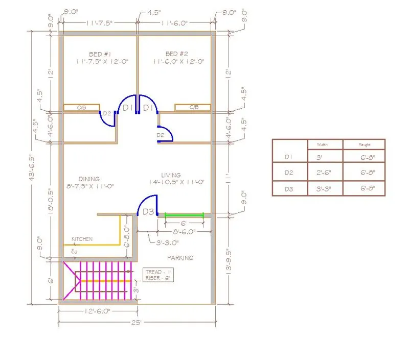
Sketch the layout of a residence as shown in the Figure 1. Consider all dimensions as reference to sketch the unit plan. Also the text in the layout are only for reference. Assume the missing dimensions. Also, refer the schedule for size of the doors.
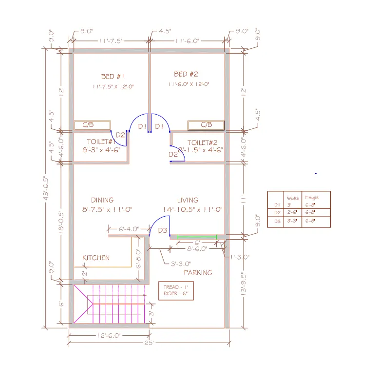
1.Ans:
AIM:- To draw a residence plan of given layout with the use of AutoCAD
PROCEDURE:-
- Click on AutoCAD application and open the application
- Type a command StartUp and enter the value 1
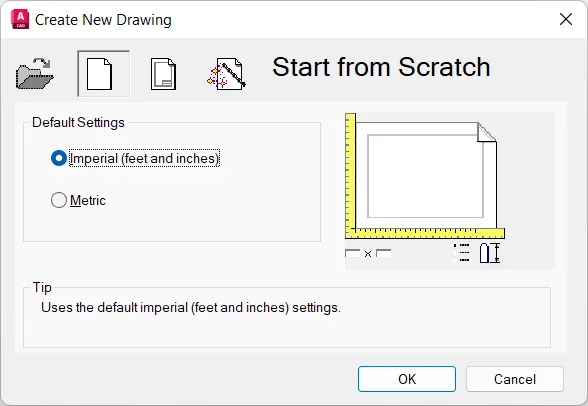
- Select the Imperial (Feet and inches)
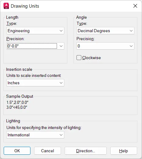
- Select Engineering type,0'-0.0" in precision,insertion scale units in inches,decimal type and precision in 0 for decimal.Click OK
- Type a command limmax
- Enter new value for limmax:- 100',100'
- Type a command zoom and select all
- Type a command limits
- Specify lower left corner:- 0,0
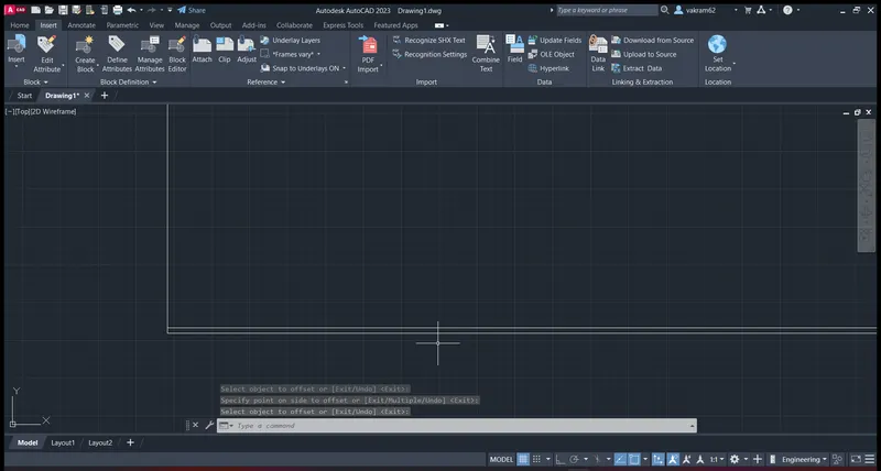
- Specify upper right corner:- 70',70'
- Type a command zoom and then select all
- Type a command XLINE
- Specify the line:- Vertical
- Specify through point:- Click it anywhere
- Type a command XLINE
- Specify the line:- Horizontal
- Specify through point:- Click it anywhere
- Type a command and then trim at corner edge
- Type a command:-Offset
- Specify offset distance:- 9"
- Type a command:- Offset
- Specify offset distance:- 43'6.5"
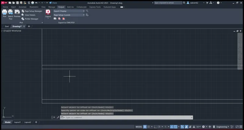
- Type a command offset
- Specify offset distance:- 9"
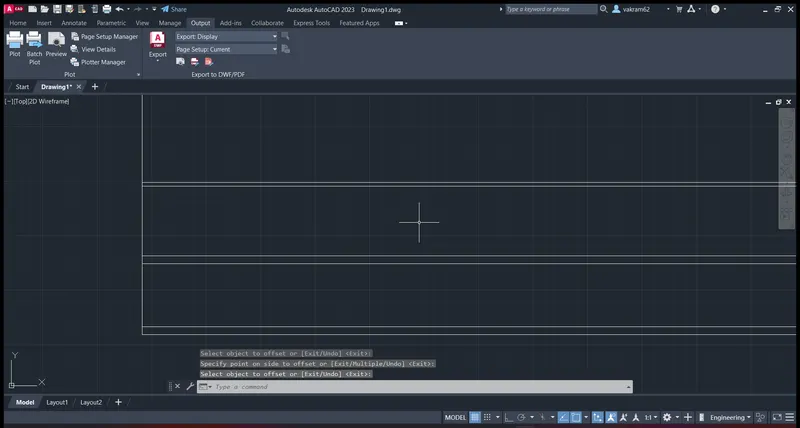
- Type a command offset
- Specify offset distance:- 25'
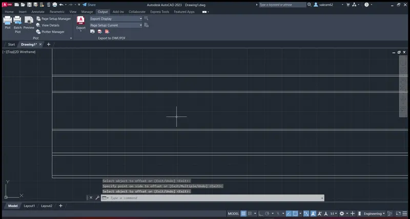
- Type a command trim and then trim the unwanted lines
- To draw a bed 1, type a command offset
- Specify offset distance:- 11'7.5"
- To draw an inner wall, type a command offset
- Specify offset distance:- 4.5"
- Type a command offset
- Specify offset distance:-12'
- Type a command trim and then trim the unwanted lines
- To draw a bed 2,type a command offset
- Specify offset distance:- 11'6"
- Type a command trim and trim the unwanted lines
- To draw a toilet 1, type a command offset
- Specify offset distance:-4.5" for interior wall
- Type a command offset
- Specify offset distance:-4'6"
- Type a command offset
- Specify offset distance:-4.5" for interior wall
- Type a command offset
- Specify offset distance:-8'3"
- Type a command offset
- Specify offset distance:-4.5"
- Type a command trim
- Trimmed the unwanted lines
- To draw a toilet 2, type a command offset
- Specify offset distance:-8'1.5"
- Type a command offset
- Specify offset distance:-4.5"
- Type a command trim
- Trim the unwanted lines
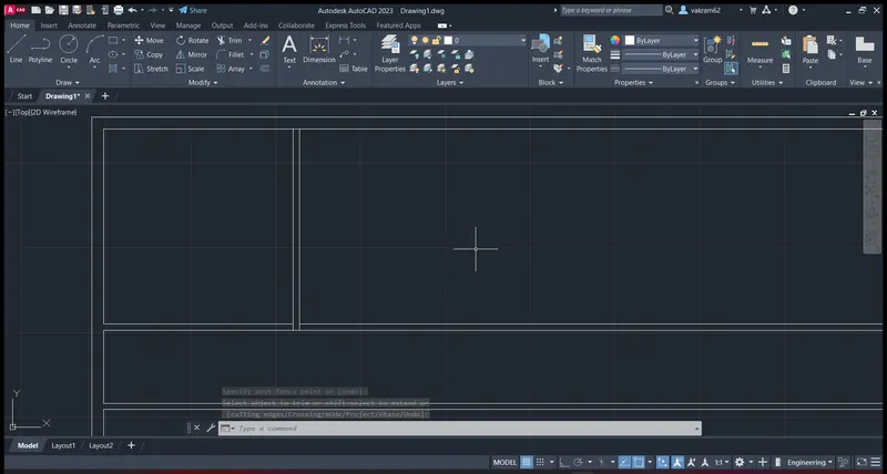
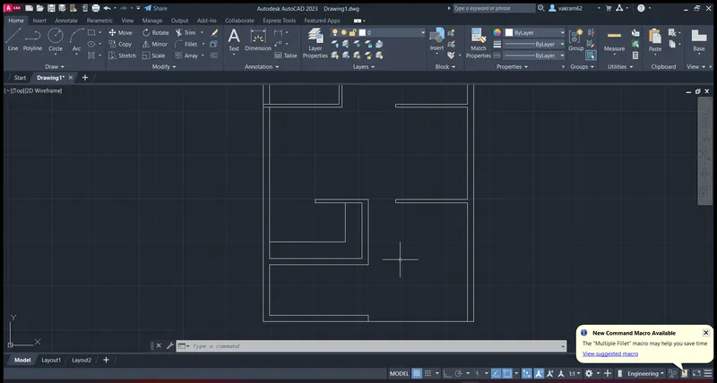
- To draw a kitchen, type a command offset
- Specify offset distance:-2'
- Type a command offset
- Specify offset distance:-6'8"
- Type a command offset
- Specify offset distance:-11'7.5"
- Type a command offset
- Specify offset distance:-9"
- Type a command offset
- Specify offset distance:-6'4"
- Type a command trim
- Trimmed the unwanted lines
- To draw a living room, type a command offset
- Specify offset distance:-11'
- Type a command offset
- Specify offset distance:-9"
- Type a command trim
- Trimmed the unwanted lines
- To draw a door section, type a command circle,offset and extend
- To draw a staircase, Specify offset distance for 1' for each step ( 9 steps)
- Select the mid point of the line and draw an inclined line at the end point of it
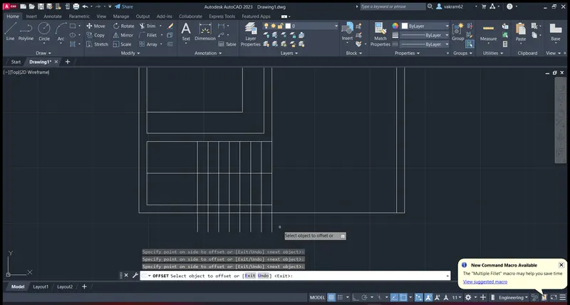
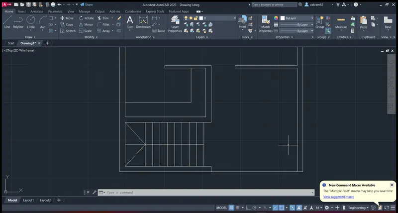
- Type the OPtions commond
- Then select the colour option and chance into white background
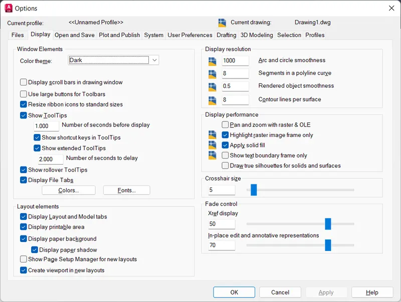
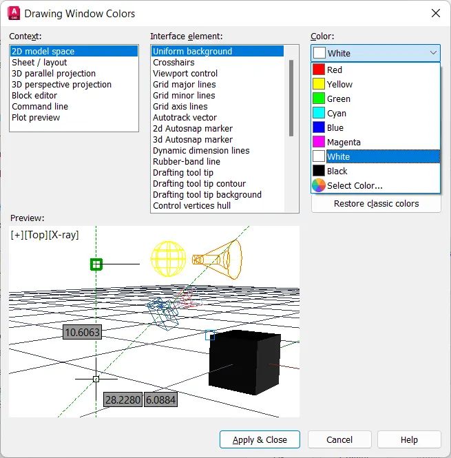
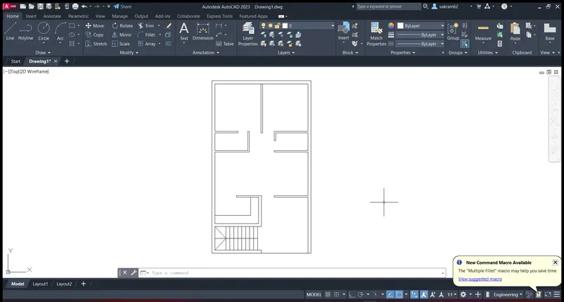
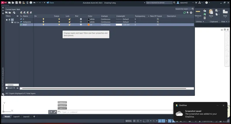
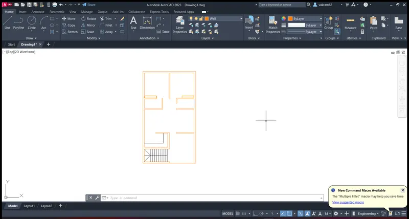
- Enter the layer commond
- Enter the name as Wall and select the colour
- And given the linewieght
- Then set as current layer, select the object and press enter.
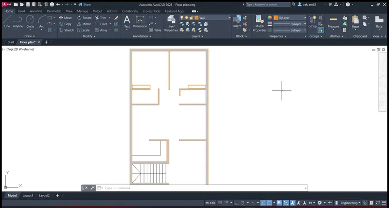
- Enter the Hatch commond
- Select the solid and colour
- Then select the object
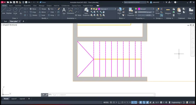
- Enter the layer commond
- Creat new layer named as Staircase
- Set as current layer
- select the object and press enter
Similarly, Creating the other layers with colour and linewieght
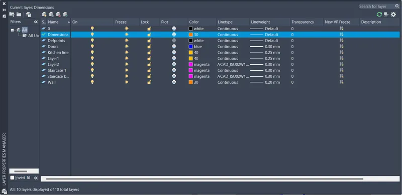
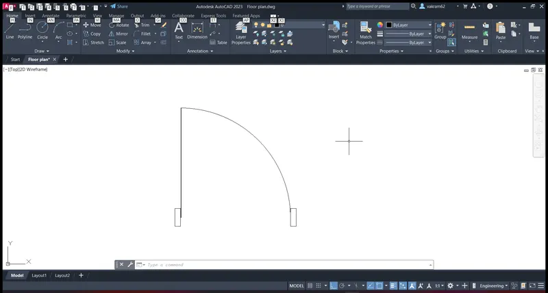
- To drawn the Doors with three different sizes
- Enter the Block commond
- Select the pickup point
- Select the object
- Press enter
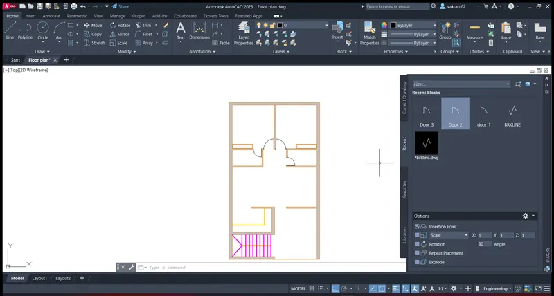
- Enter the insert commond
- Drag the door blocks at suitable points
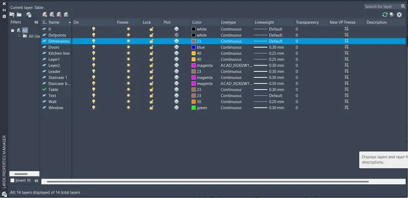
- Enter the layer commond creating the new layer named as dimensions
- Select the colour
- set as current layer
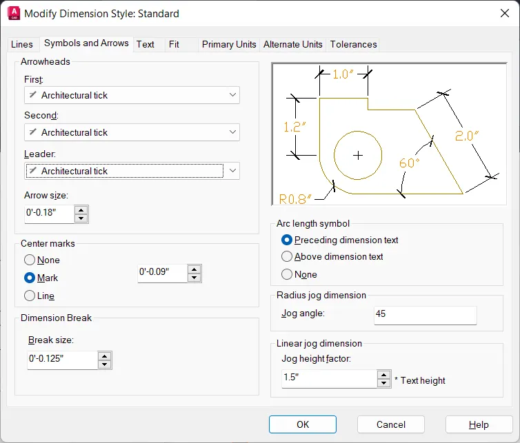
- Enter the Dimensions style commond
- In Symbols and arrows changing the Arrowheads
- In Text option select the colour and in Fit option choose the scale factor as 50 units
- Specify the all the dimensions according to layout
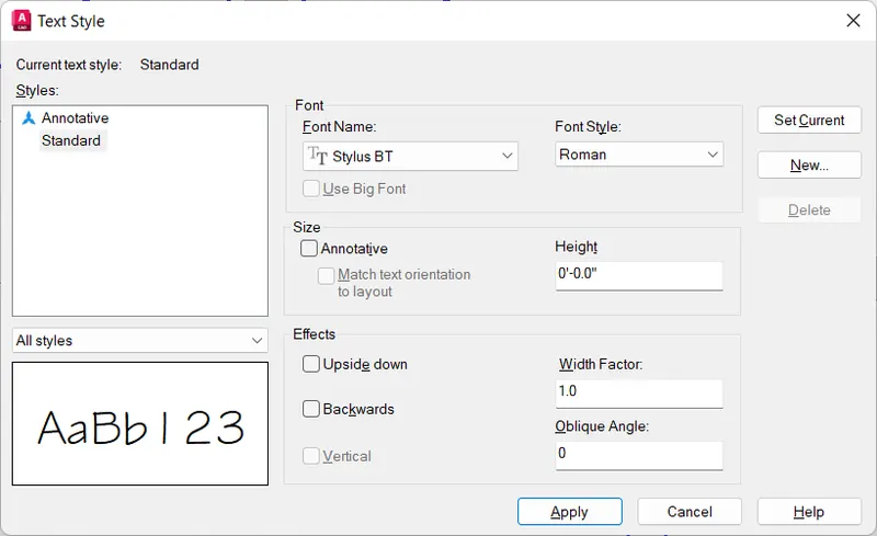
- Change the Text Style and Apply it, set as cuurent
- Go to Annotate and select the Multi text
- Write the room names with dimensions
Result : Given layout is drawn successfully with AutoCAD tools like Line,Xline,Circle,Trim,Rotate,Rectangle,Layers,Block,Insert,Dimsensions ect.,
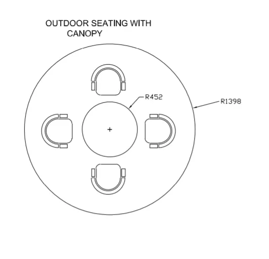
2. Sketch the seating plan for an outdoor canopy. Assume the dimensions for the seating. Also, consider the dimensions in mm.
2.Ans:
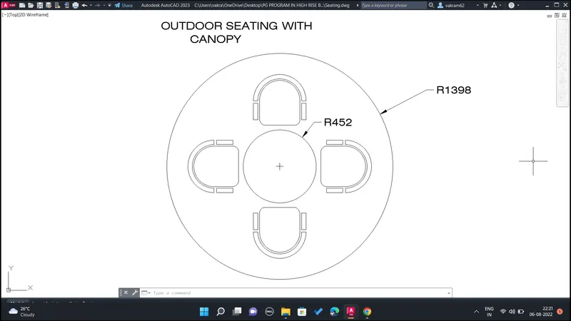
AIM:- Sketch the seating plan for an outdoor canopy of figure 2 with the use of AutoCAD Tools
PROCEDURE:-
- Click on AutoCAD application and open the application
- Type a command QNEW to save the file
- Type a command units.
- Select decimal type,0 in precision,insertion scale units in millimetres,decimal type and precision in 0 for decimal.Click OK
Step-1:
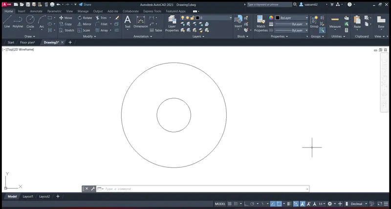
- Type a command circle
- Specify the first point
- Specify radius of circle:-452
- Type a command circle
- Specify centre point of the circle
- Specify radius of circle:-1398
-
Step-2
- Give a Command of L and Press Enter
- Specify the Starting point Give length as 300 mm in -Y Direction
- Move the Cursor to X Direction Give the Length as 600 mm
- Move the Cursor to Y Direction Give the Length as 300 mm
- Give the Command of Arc in Command Bar Press Enter
- Select the Start and End Point From Command Bar
- Press Esc.
- Give the Offset Command Bar and Pres Enter
- Select arc and Give the 50 mm Offset
- Join the Ends of arc Using Line
- Give the Command of Rec For Rectangle Draw in Arc Alignment With a Required Dimensions With Both Sides
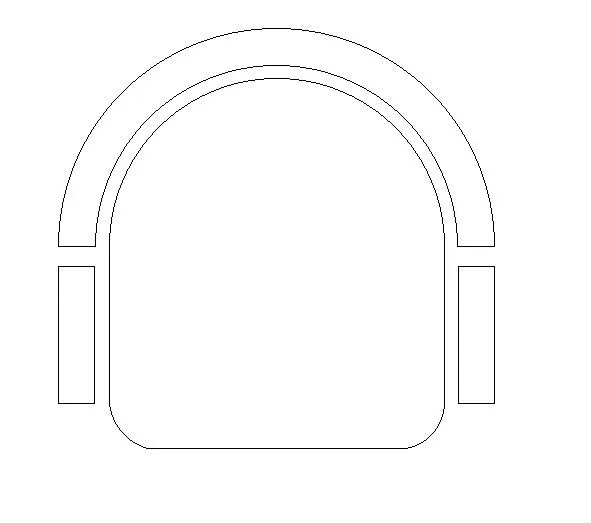
- Enter the block and named as chair
- Select the pickup point
- Select the object
- Press enter
- Enter the Insert commond
- Drag the block
- Place the chair at required point i.e, center of circle and line touches to the centre of chair, offset from circle
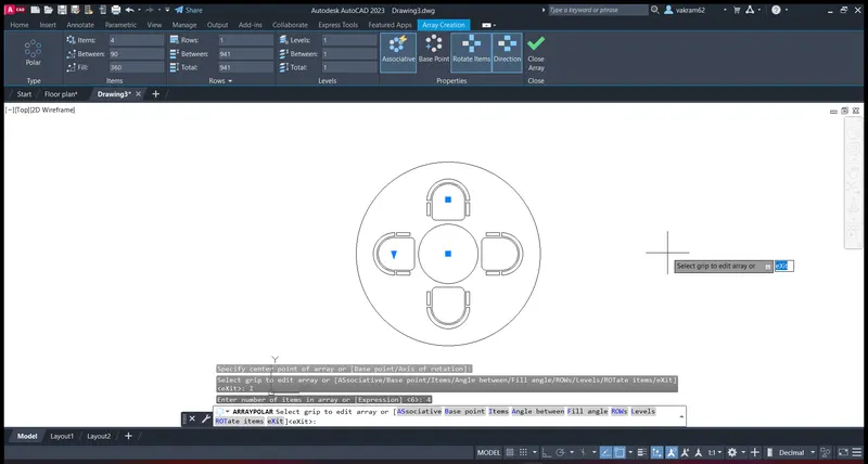
- Select the array commond
- Select the Polar Array
- Specify the number of items as 4
- Specify the centre of circle
- Arranged automatically
- Dimensions of the above geometry is done with the use of command Dim Radius
RESULT:- The above seating plan is done with the use of AutoCAD Tools
3. Sketch the part plan for the toilers and utilities room. Consider the outer wall thickness as 300mm and inner wall thickness as 150mm. Also, assume the missing dimension, Texts, dimensions, and hatches are only for references. Also, symbols for toilets and w/c are also for references.
3.Ans:
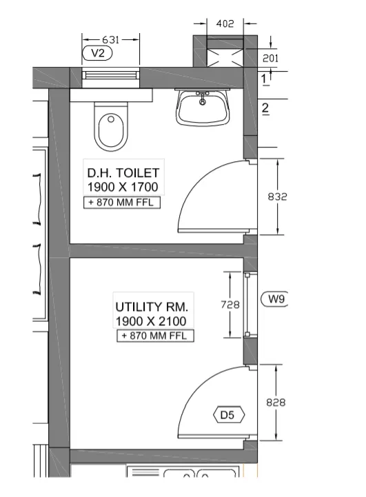
Aim: - Sketch the part plan for the toilers and utilities room
Procedure: -
Step-1
- Give the Command of X Line Select H and Enter Place at Corner of Work Space
- Give the Command of X Line Select V and Enter Place at Left Corner of Work Space
Step-2 :-
- Give Offset Command and Press Enter
- Give the Offset Distance of 300 and Select the Object and offset it
- Give Offset Command and Press Enter
- Give the Offset Distance of 1900 and Select the Object and offset it
- Give Offset Command and Press Enter
- Give the Offset Distance of 150 and Select the Object and offset it
- Give Offset Command and Press Enter
- Give the Offset Distance of 150 and Select the Object and offset it
- Give Offset Command and Press Enter
- Give the Offset Distance of 2100 and Select the Object and offset it
- Give Offset Command and Press Enter
- Give the Offset Distance of 150 and Select the Object and offset it
- Give Offset Command and Press Enter
- Give the Offset Distance of 1700 and Select the Object and offset it
- Give Offset Command and Press Enter
- Give the Offset Distance of 300 and Select the Object and offset it
Step-3
- Trim Corner Lines and Unnecessarly Line By Using Trim Command
- Give Offset Command and Press Enter
- Give the Offset Distance of 150 and Select the Object and offset it
- Give Offset Command and Press Enter
- Give the Offset Distance of 631 and Select the Object and offset it
- Give Offset Command and Press Enter
- Draw a Line In Middle Using Line By Command L Enter and Keep Orho on and Select Middle Point and Apply it.
- Give the Offset Distance of 150 and Select the Object and offset it
- Give Offset Command and Press Enter
- Give the Offset Distance of 832 and Select the Object and offset it
- Give Offset Command and Press Enter
- Give the Offset Distance of 150 and Select the Object and offset it
- Give Offset Command and Press Enter
- Give the Offset Distance of 728 and Select the Object and offset it
- Draw a Line In Middle Using Line By Command L Enter and Keep Orho on and Select Middle Point and Apply it.
- Give Offset Command and Press Enter
- Give the Offset Distance of 150 and Select the Object and offset it
- Give Offset Command and Press Enter
- Give the Offset Distance of 832and Select the Object and offset it
- Draw a Rectnagle by Using Command of Rec Enter and Specify the Corner Point of Wall Give Dimenstion of Length 402, Width 201 Press Enter
Step 4
- Fillet the Corner Points By Give the Command of Fillet and Press Enter
- Trim Unnecessary Lines By Give the Command Trim and Enter
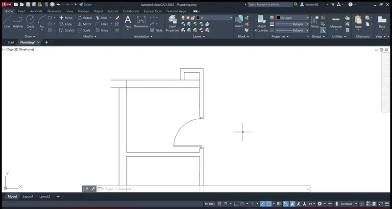
Step 5 :-
- To Create Door, Give the Command of Circle and Press Enter
- Select the Corner Point of Door Drag the Circle Until Touches End Point
- Follow the Same Procedure to Create another Doors
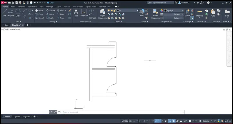
Step 6:-
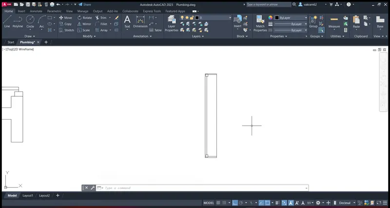
- Enter the line commond
- Specify the first point and give the length of 728 units
- And offset it with 100 units
- Creating small sqares using the rectangle commond
- Specify the sqares at corner point on both sides of window
- Enter block commond with named as Window
- Pickup and select the object press eneter
- Enter insert commond and place it at their position
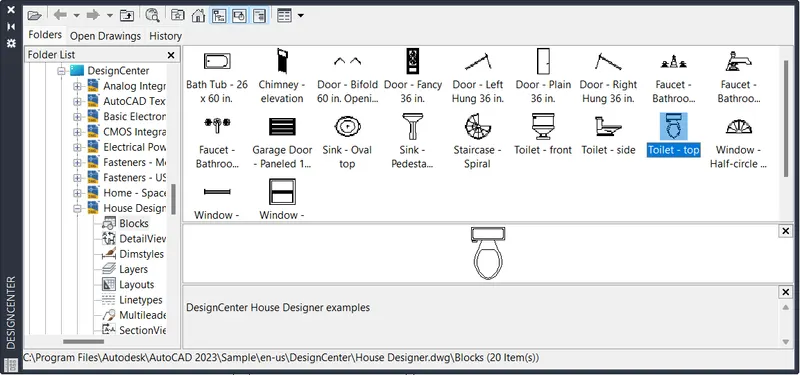
Step-7:-
- Enter the ADC commond
- In design center option using the blocks drag the Toilet top and sink
- Place at correct positions
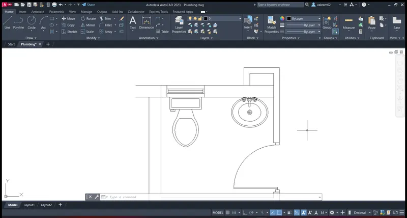
Step-8:-
- Enter the line commond
- Specify the first point and the length of 631 units
- Eneter offset and value of 200 units
- Similarly through offset give the direction to it
- Block the object and insert at their posion
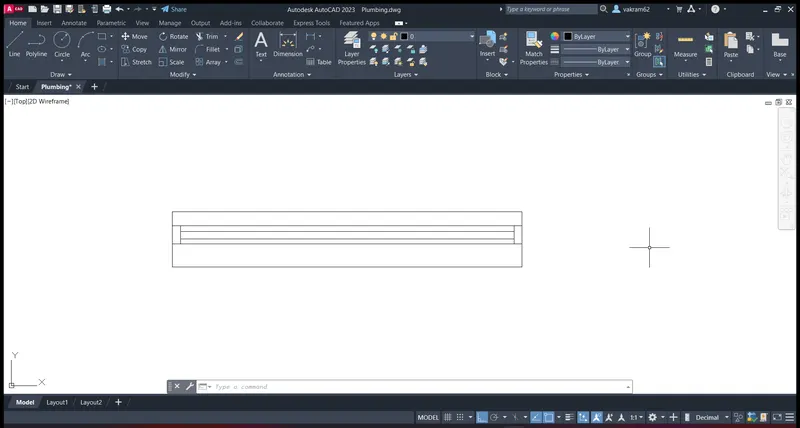
Step:-9
- Enter Dimension commond
- Specify all the needed dimensions
Step-10
- Select the Annotate and click on Multitext
- Specify the point on screen
- Write the Room names with dimensions
Result:- Drawn the part plan for the toilers and utilities room with the use of AutoCAD Tools
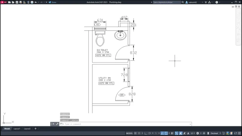
Layers:-