Creating a Layout, Section and Elevation with dimensions using AutoCad
AIM
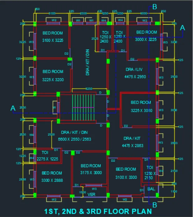
To create Plan, Elevation, and Section as shown in figure
COMMANDS USED
- Line
- Rectangle
- Polygon
- Offset
- Extend
- Trim
- Fillet
- Chamfer
- Mirror
- Move
- Rotate
- Dimension
- Text
- Array
PROCEDURE
The dimensions are
- WALL
- External wall - 250mm g
- Interior wall - 125mm
- Staircase -
- Thread = 250mm
- Rise = 150mm
- WINDOWS
- W - 1000 * 1500
- W1 - 900 * 1200
- W2 - 1200*1200
- W3 - 1500 * 1200
- W4 - 700 * 500
- DOORS
- D - 1000*2000
- D1 - 750 * 2000
- D2 - 900 * 2000
STEPS FOR PLAN
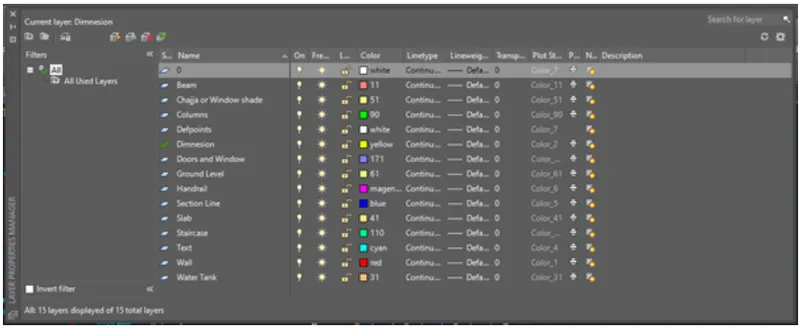
- Open AutoCAD and enter the Unit and Limit command
- Select the X-Line command and draw a horizontal line and vertical line
- Select offset command 250mm to both horizontal and vertical line drawn by X line
- give the offset as follow in the X direction
- Offset 3100 for bedroom
- Offset 125 for internal wall
- Offset 2250 for kitchen / drawing room / dining room
- Offset 125 for internal wall
- Offset 1250 for both toilet
- Offset 250 for external wall
- Give the offset as follows in the X direction
- Offset 3100 for bedroom
- Offset 250 for a wall on both sides of the stairs
- Offset 250 for thread
- Offset 1200 for the landing of the staircase
- Offset 2400 for the width of the staircase
- Offset 2250 for kitchen dining bedroom
- Offset 1000 for veranda
STEPS FOR DRAWING SECTION AA
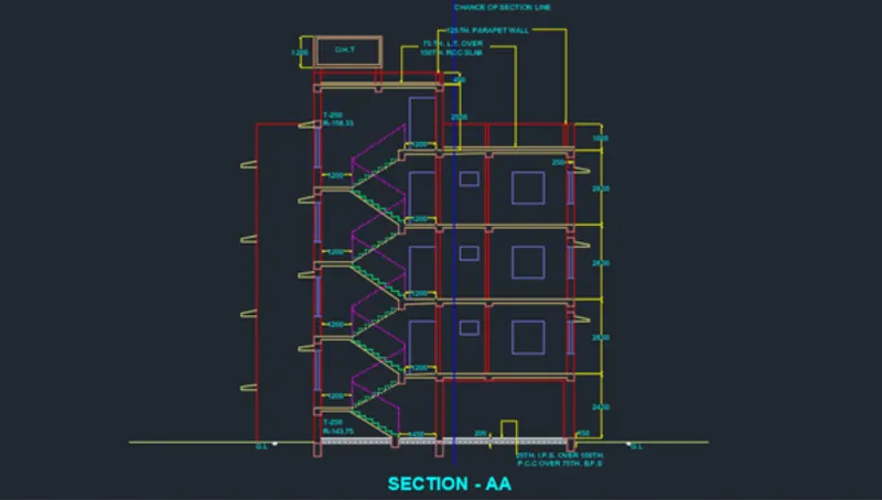
- Select XL line command and extend the line from the plan downwards to create a projection
- Offset 150 from ground level
- Offset 2450 for the ground floor
- Offset 2850 for the first, second, and third floor
- Offset 1000 for parapet wall
- Offset 2500 from terrace level
- Offset 450 from terrace level for parapet wall
- Offset 600 and 1200 for OTH
- For drawing of staircase offset 1250 for thread and offset 143.75 for rising the of staircase
- Offset 125 below floor level for slab
- Draw the chajjas and windows as per size considered and standards
- Drawing the railing of the staircase in-dash manners from the layers and change the layers type
- Give dimensions by dim linear or the dim continue command
- Draw doors and windows of a given size
- Select the multiline text for the naming of a section
STEPS FOR DRAWING SECTION BB
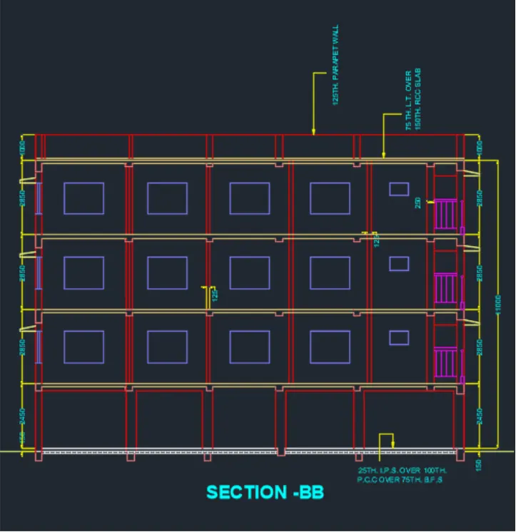
- Rotate the entire plan to a 90 degree to draw section BB
- Select XL command and take projection
- Take interior wall dimension as 125mm and external wall dimension as 250mm
- Draw a baseline
- Offset 150 from baseline
- Offset 2450from ground level
- Offset 2850 for the first, second, and third floor
- Offset 1000 for parapet wall
- Thickness of slab is assumed to be 125mm
- Offset 125mm on each floor downwards
- Give dimensions by dim linear or the dim continue command
- Draw doors and windows of a given size
- Select the multiline text for the naming of a section
RESULT
The given plan and section are created using AutoCAD.