Creating a Layout, Section and Elevation with dimensions using AutoCad
Question : 01
Create the Plan and Sections as shown in the Figures. Use proper dimension techniques and dimension styles to document the project. Assume the sizes of the doors and windows as per construction standards. Refer to sections for stair details if required.
(Answer):
Aim: To draw the floor plans and sections using the proper dimension techniques and dimension styles to document the project.
Introduction:
- Plan and Sections are different types of drawings used by architects to graphically represent a building design and construction.
- A plan drawing is a drawing on a horizontal plane showing a view from above.
- An Elevation drawing is drawn on a vertical plane showing a vertical depiction.
- A section drawing is also a vertical depiction but one that cuts through space showing what lies within.
Commands Used:
- Limits command
- Line command
- Offset command
- Hatch command
- Dimlinear command
- Dimstyle command
- Units command
- Extend command
- Fillet command
- Trim command
- Join command
- Line weight command
- Line type command
- Object snap command
Procedure:
Plan:
Step 1:
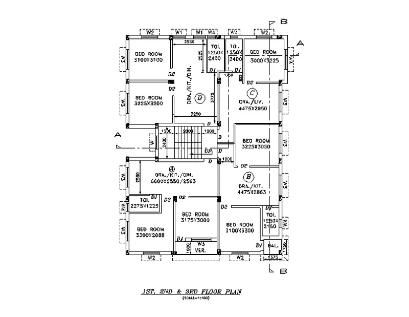
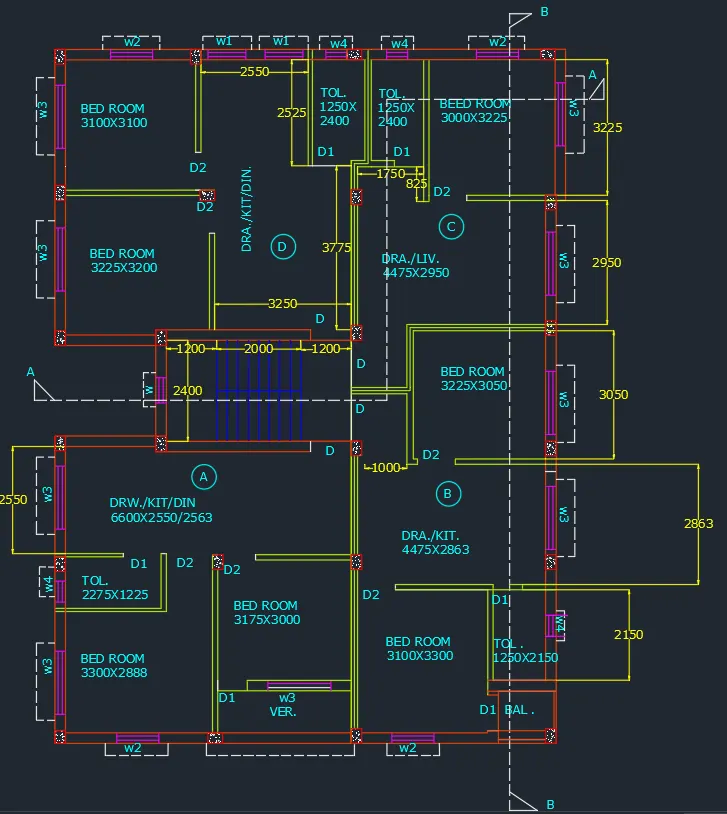
Drawing the plan:
- Given outer wall thickness as 250mm and inner wall thickness as 125mm.
- Draw XL-h and Xl-v give the wall thickness.
- Give the dimensions of rooms bed room(3100x3100) mm by offset method.
- Give inner wall dimension as 125mm by offset method.
- Offset horizontally 2550mm ,125mm, 1250mm(toilet) ,125mm,125mm,1250mm (Toilet of C) ,3000mm (bedroom of C),250mm (external wall)
- Offset vertically 2400mm (toilet) and 125mm ,3225mm (bedroom of) .125mm (wall thickness).
- Offset vertically 2950mm (drawing/living) from bedroom of C and give wall thickness of 125mm ,3250mm and 3200mm give wall thickness of 250mm.
- Divide the rooms horizontally by offsetting 3225mm,125mm,3250mm,125mm,4475mm,250mm.
- Offset 2400mm vertically and 4400mm horizontally for the staircase.
- Offset 3050mm vertically from drawing of C and 3225mm horizontally for the bedroom of B and offset the wall thickness also.
- Offset 3300mmvertically and 3100mm horizontally for the front bedroom.
- Fillet the wall of the bedroom with the left side wall and give wall thickness of 250mm.
- Offset 100mm from the outer wall, Draw verandas by offsetting 1000mm and offset 3175mm for the bedroom of A.
- Offset 2888mm for the front bedroom of A and offset wall thickness of 125mm.
- Offset 1225 and 2275 mm for the toilet, then offset 2550mm for the drawing/kitchen/dinning of A.
- Fillet all the corners and trim the excess lines .
Step 2:
Creating Doors and windows:
For doors and windows following diamensions are assumed:
D- 1000x2100mm W1-900x1200mm
D1-700x2100mm W2-1000x1200mm
D2-900x2100mm W3-1500x1200mm
W4-500x500mm
W-600x1200mm
- Trim off the size of doors on the walls, wherever door is required.
- Create windows of given sizes and place it in respective places.
Step 3:
Text:
- With multiline text, command "MT"- create text box, select standard as text style aerial text height as 250mm, type the required text.
- Names of rooms with sizes and marking of windows and doors.
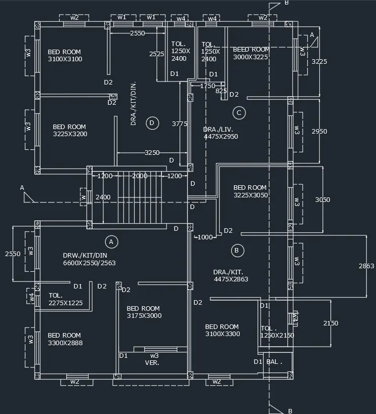
1st,2nd ,3rd floor plan.
Scale 1:100.
SECTION:
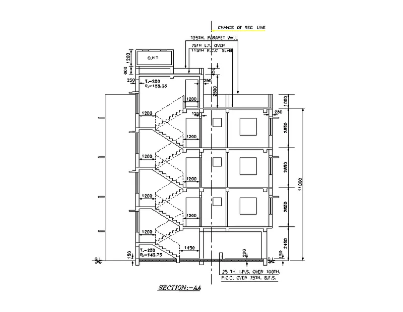
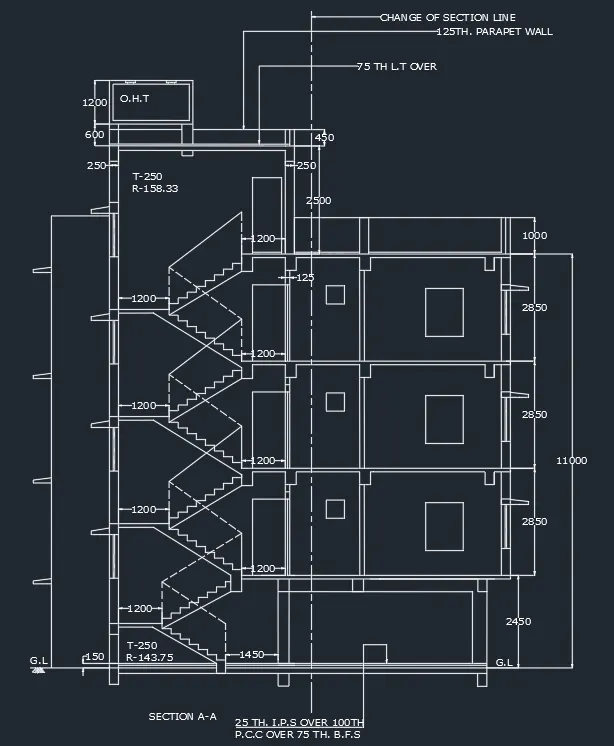
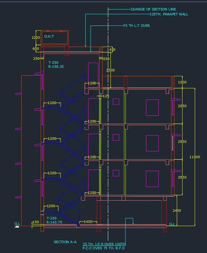
Section A-A:
- Assumed dimensions:
- Slab thickness -100mm
- Beam - 300 x350 mm
- Lintel level from floor- 2100mm
- Lintel thickness - 150mm
- Staircase waist slab thickness, landing slab thickness- 100mm
- Height of newel post -1000mm
Extend the wall thickness wherever the section cuts the plan.
Then draw a horizontal line to show the ground level.
Draw 150mm thickness from the ground level by offsetting 150mm from ground level.
Offset a distance of 2450mm from the ground level for the ground floor height.
Give the slab thickness of 100mm from the top level.
Draw beams wherever the walls are there beam size of 300x350mm.
Draw columns of 400mm and 300mm width.
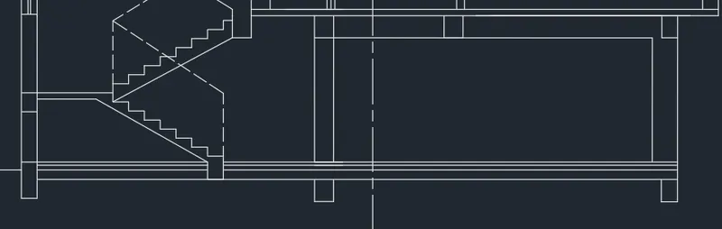
Drawing of stairs:
- Draw beam of 300mm width and 270mm depth down the ground level.
- At a distance 1450mm from the 300mm column draw vertical line of 143.75mm (riser), except the top floor 143.75mm
- Draw horizontal line of 250mm.(tread)
- Similarly draw 8 steps, draw the landing from the 8th one and offset a thickness of 100mm downwards.
- Draw an inclined line joining the riser end of the flight, offset 100mm from that line (waist slab), then join it with the landing slab.
- Mirror the steps to the opposite side meeting the next floor, given dotted lines as it won't be visible
- Draw beam of 300x250mm as landing beam.
- Give the height of newel post as 1000mm on both the start and end of flight, connect it with inclined line.
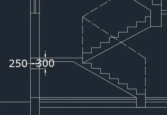
For the first floor, offset a height of 2850mm, also give slab thickness of 100mm and beam of 300x350mm.
Extend the projected walls of 125mm and 250mm.
Extend the doors and windows from the plan to get its width, then height is given 1200mm for window and 50mm for ventilator.
Draw lintel slab of 150mm and projection of shade as 400mm.
Show section of the window on one end of wall and the stair side as it is cut by the section line.

Similarly copy the same in the respective floors , up to 3rd floor.
On top for parapet give height of 1000mm and 2500mm for the top room.
Draw a door of 900x 2100mm door and wall thickness of 250mm on both sides.
For overhead water tank, draw a parapet height of 450mm.
Extend the wall thickness and the beam.
For tank, draw a line of 1200mm as height of tank and 2300mm as width of tank.
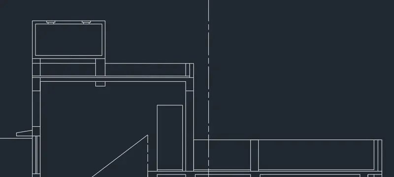
With the use of multileader text are written.
- Select leader from annotate tab - multileader style manager dialogue box displays.
- Create new - then give the leader points as 5, text height as 250mm and arrow size as 1000mm.
- Parapet walls are marked.
TEXT:
With multiline text, command "t"- create text box, select standard as text style aerial text height as 250mm, type the required text.
Tread and riser are mentioned, Overhead water tank is marked.
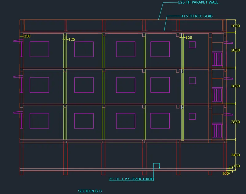
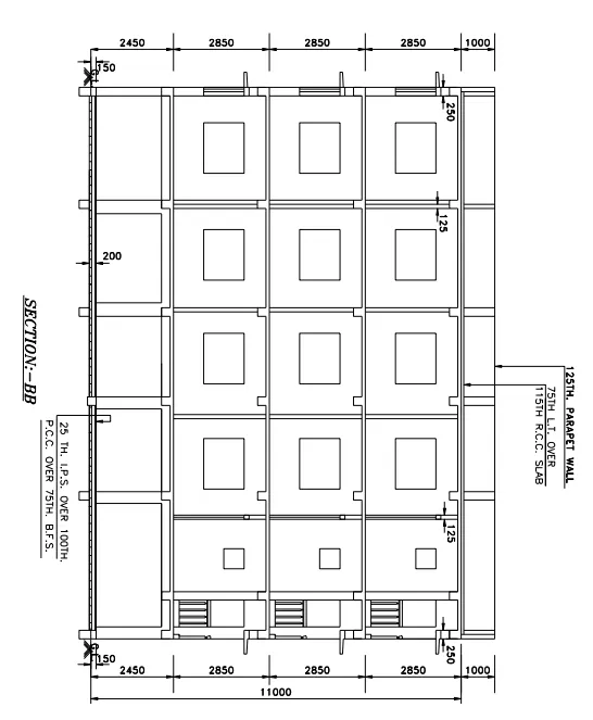
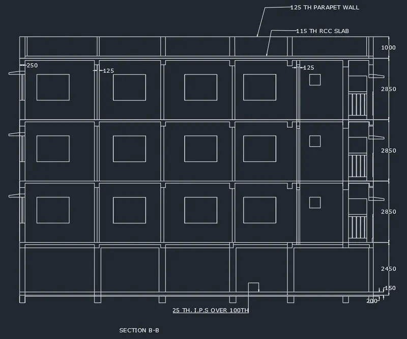
Section B-B
Project the walls and columns from the plan using line command.
Mark a vertical line showing Ground level, take offset of 150mm for P.C.C and 200mm from the ground level to show the flooring level.
Project the windows and ventilators and give the height 2100mm.
Offset slab of 100mm thickness and draw the beams.
Show the section of windows wherever the section line cuts the windows
With multileader, text size -250mm and leader point as 2, write the text.
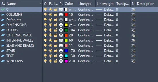
Creation and palcing the drawing elements in layers:
Layers are created by using the command "LA" create the layers and give the properties of the layers like colour,line weight,etc.
Create the layers for the walls ,text ,dimensions,etc.
Place all the elements in the respective layers.
Result:
PLAN:
SECTION A-A:
SECTION B-B: