Creating a Layout, Section and Elevation with dimensions using AutoCad
ANSWERS FOR CHALLENGE
1. Create the Plan and Sections as shown in the Figures. Use proper dimension techniques and dimension styles to document the project. Assume the sizes of the doors and windows as per construction standards. Refer to sections for stair details if required.
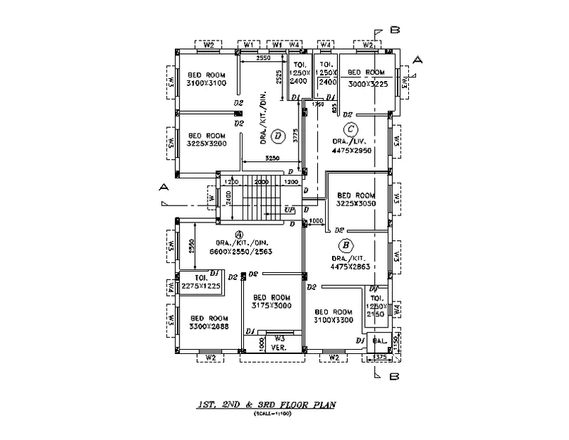
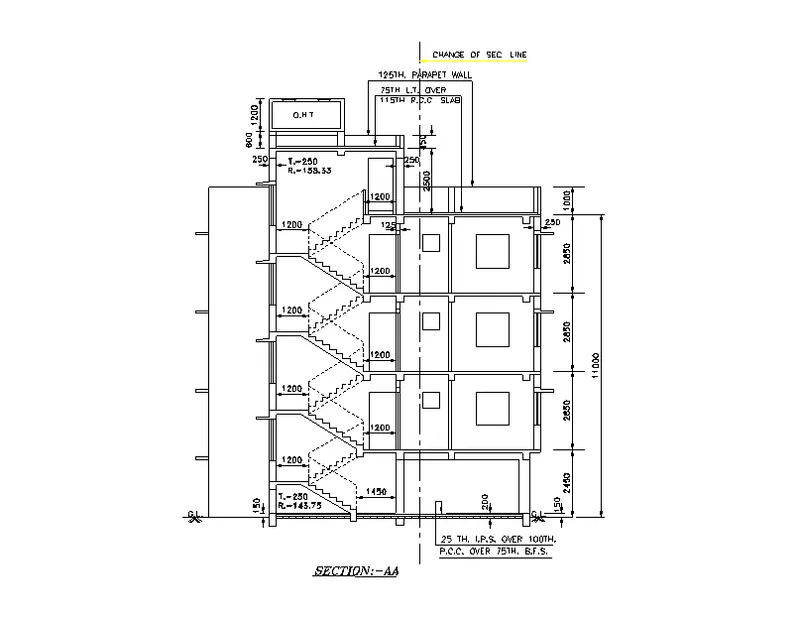
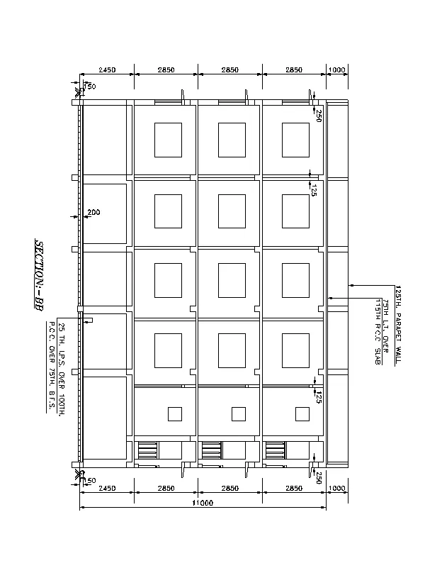
1.Ans:
AIM:- To draw the plan and section of given drawing
AutoCad used Tools:
- Line
- Polyline
- Rectangle
- Circle
- Dimension style
- Text style
- Block
- Group
- XLine
- Layers
- Trim
- Offset
- Mirror
- Copy
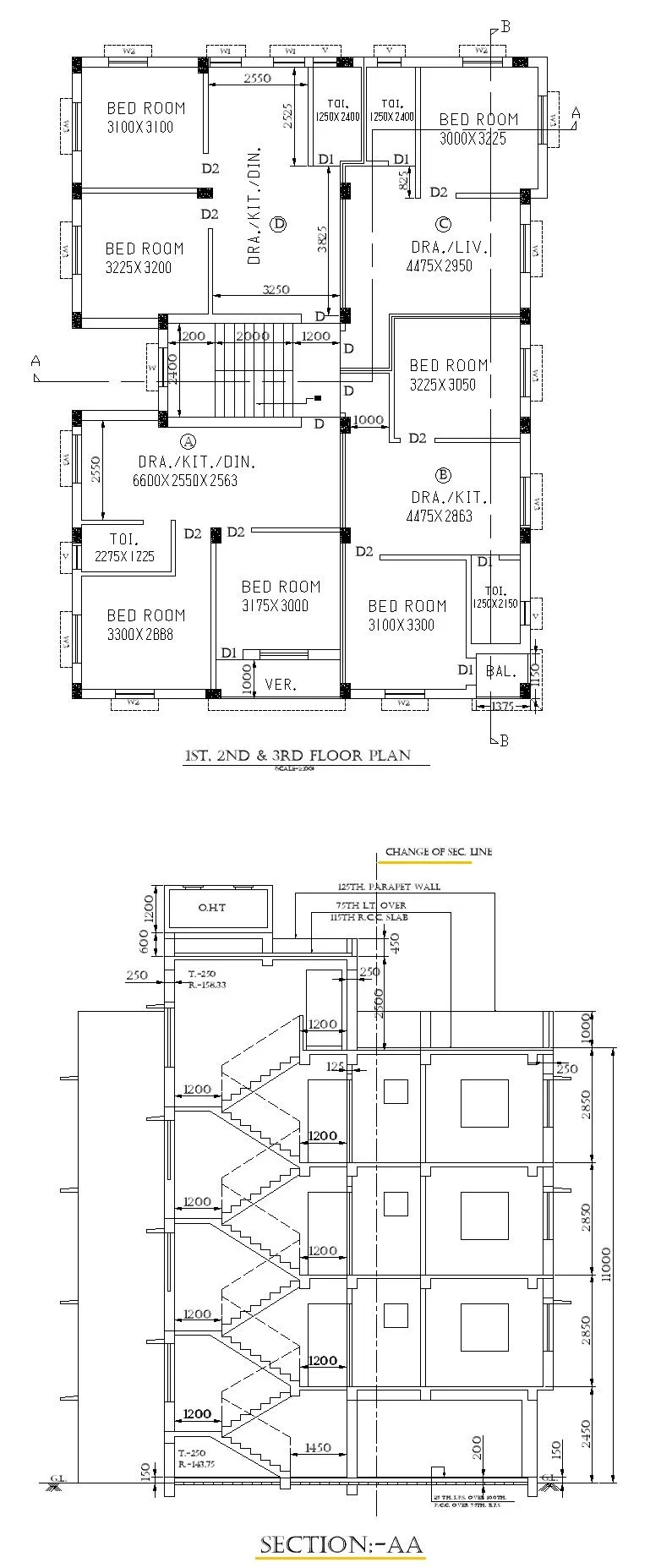
Procedure: Floor plan
Step-1
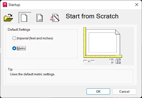
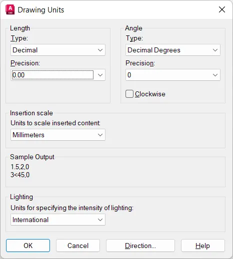
- Start the new file and select the Metric system
- Set the precision as 0.00 units
- Enter zoom commond and select all then start the drawing from base point
Step-2
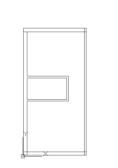
- Enter the line commond
- Specify the first point and enter the value of 16,388 units in Y-axis
- Enter the offset commond and enter the value of 250 units
- Again offset commond and enter the value of 11,450 units
- From the base point start the horizontal line in between two offset lines
- Then draw the horizontal line at the top offset line
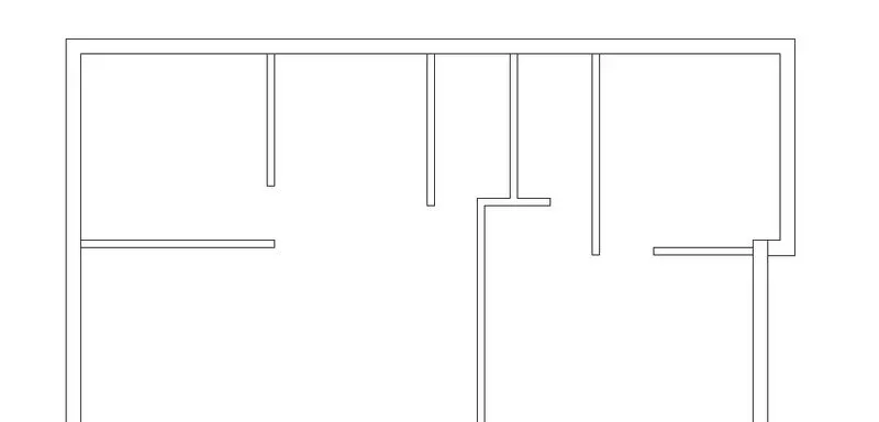
Step-3
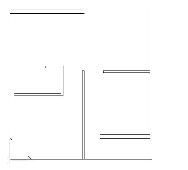
- Enter the offset commond and gives the value of 3300 in x axis as well as 2888 in y axis
- Then offset the wall thickness as 125 units and trim it unnecessary line
- Enter offset commond give the value of 3175 in x axis and 3000 in y axis simultaneously
- Trim the unwanted lines
- Again give the wall thichness as 125 units and another is 250 units
Step-4
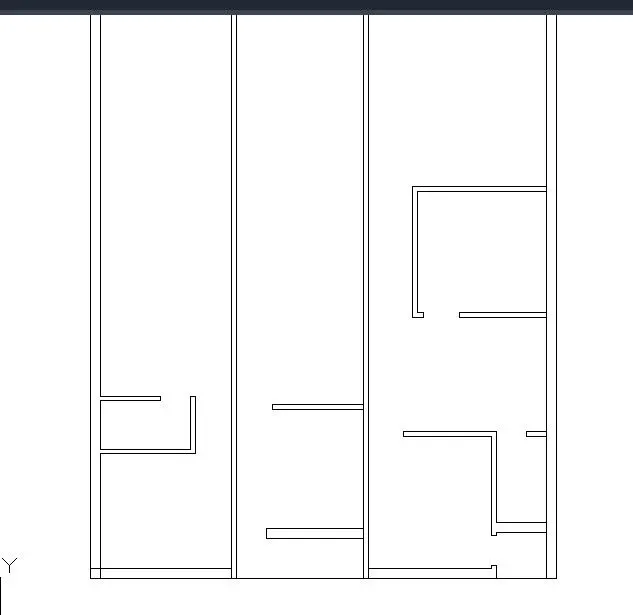
- Similarly take the offset commond and give the all rooms dimension which given in the grawing
Step-5
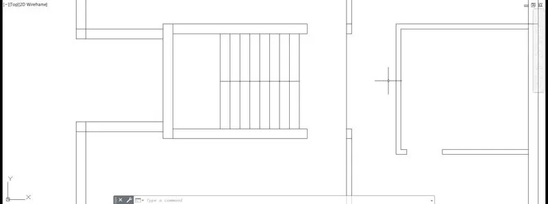
- Enter offset commond and specify the length of 1200 units which is first step of staircase having the width of 2400 units from the door(D) opening face
- Again enter the offset and specify the length of 250 units of tread and select the array option give the 8 items then click next point
- Offset the landing width having the 1200 units and offset the wall thich as 250 units
Step-6
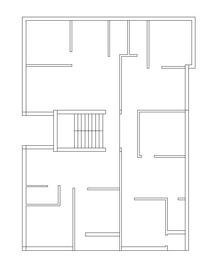
- Enter the trim commond and trim it unwanted lines
- Create the door openings having different widths
- Which is having following dimensions
- D=1000 units
- D1=700 units
- D2=900 units
Step-7
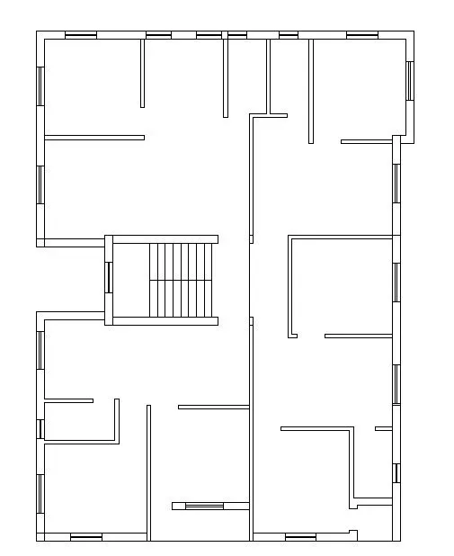
- To create the window openings following sizes are considered
- W1=800 units
- W2=1000 units
- W3=1230 units
- To create the ventilator openings following sizes are considered
- V=600 units
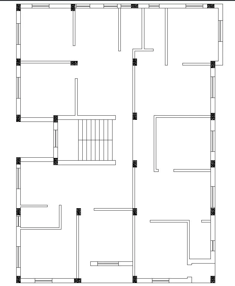
- Enter the rectangle commond and specify first point click on Dimensions and give the width 250 units, length 1230 units (W3)
- Enter the line commond draw the line in between the rectangle then offset it
- Copy the window and paste the required number of copies needed
- Place the window at desired points
- Similarly W1 and W2 windows are placed
Step-8
- Enter the rectangle commond specify the first point click on dimensions then enter the width as 250 units and length as 400 units
- Hatch the column with AR-CONC pattern
- Group the coulmn and give the name as column
- Copy the columns with required numbers
Step -9
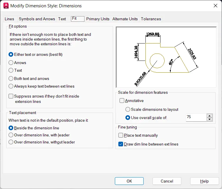
- Enter the dimension style commond and select the text font and overal scale of 75 units
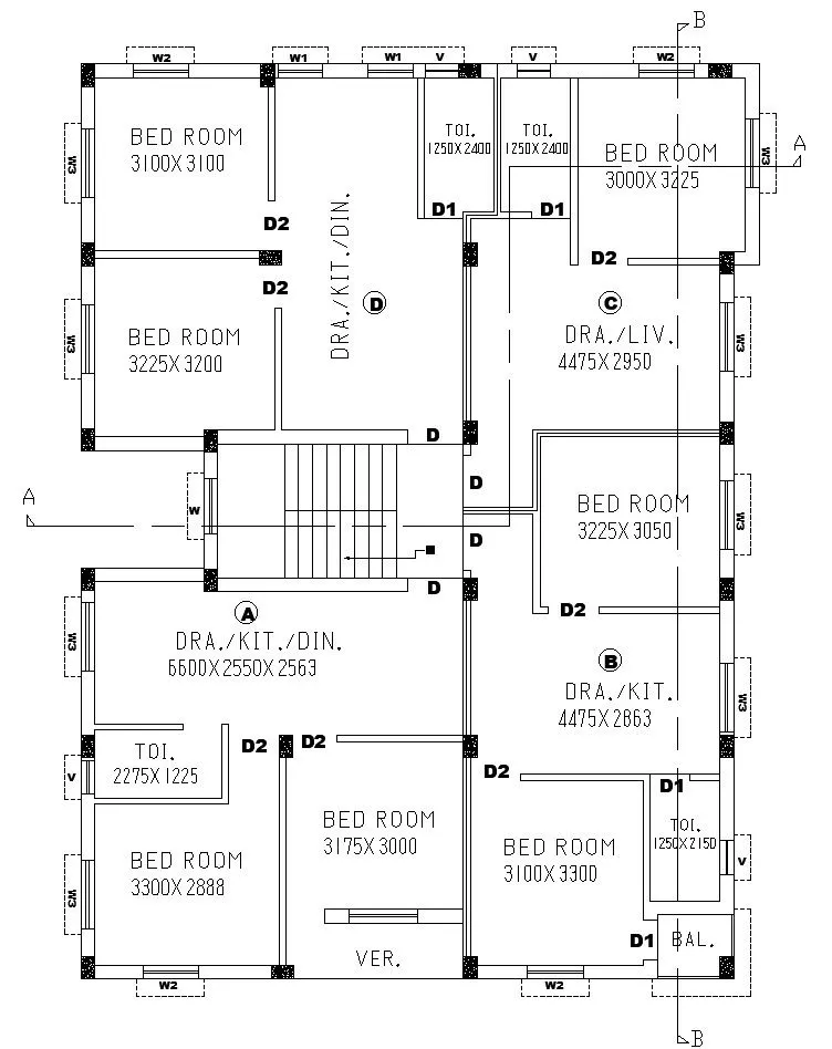
- Enter the Mtext commond start the writing the room names and dimensions
- Specify all the door numbers
- Specify all the window and ventilator names
- Enter the line commond and cut section as per drawing
- Section line layer property was changed to dash line type and text it as AA and BB
Step-10
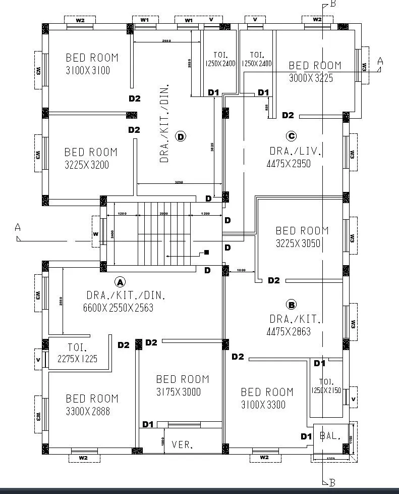
- Enter the dimension commond and Specify the required mesurements as per drawing
Step-11
- Creating a plan as per given drawing by using AutoCad tools
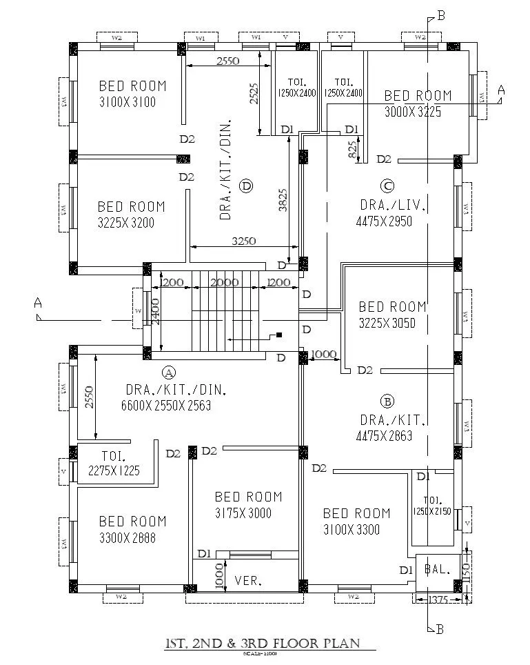
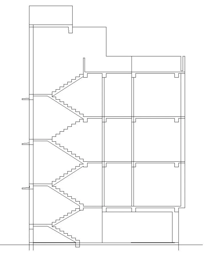
Procedure: SECTION-AA
Step-12
- Enter the xline in common specify the all the neended points
- Enter the line and draw the horizontal at top
- Trim it unwated lines
- Offset the top horizontal line having the value of15150 units
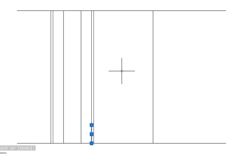
Step-13
- Enter the offset commond and specify the length as 2450 units
- Continue the offset with the values of 2850,2850,2850 and 1000 units
- Enter the polyline start the first step with 143.75 riser from the coulmn face of 1450 units
- Continue with 143.75 riser and 250 tread upto landing
- Then from the coulmn face 1200 units it will again another flight is started for this time from column face 1200 units width is consider for first floor
- Change the tread and riser as 250 and 158.33 units simultaneously
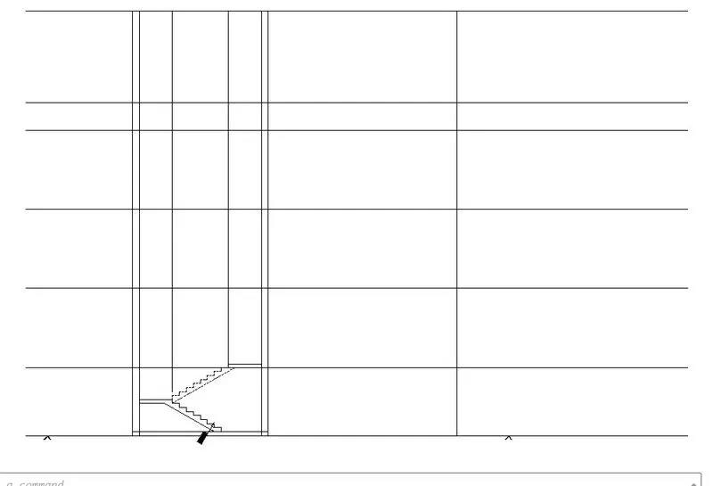
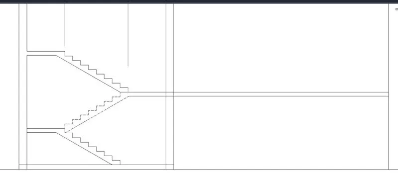
Step-14
- Enter the offset commond and specify the overheadroom top as 2500 units
- Again offset as 600 units and 1200 units upto over head tank top
- Offset the slab thick as 115 for all slabs
- Eneter line and specify the 400 units from the slab for beams
- Trim the all unwanted lines
Step-15
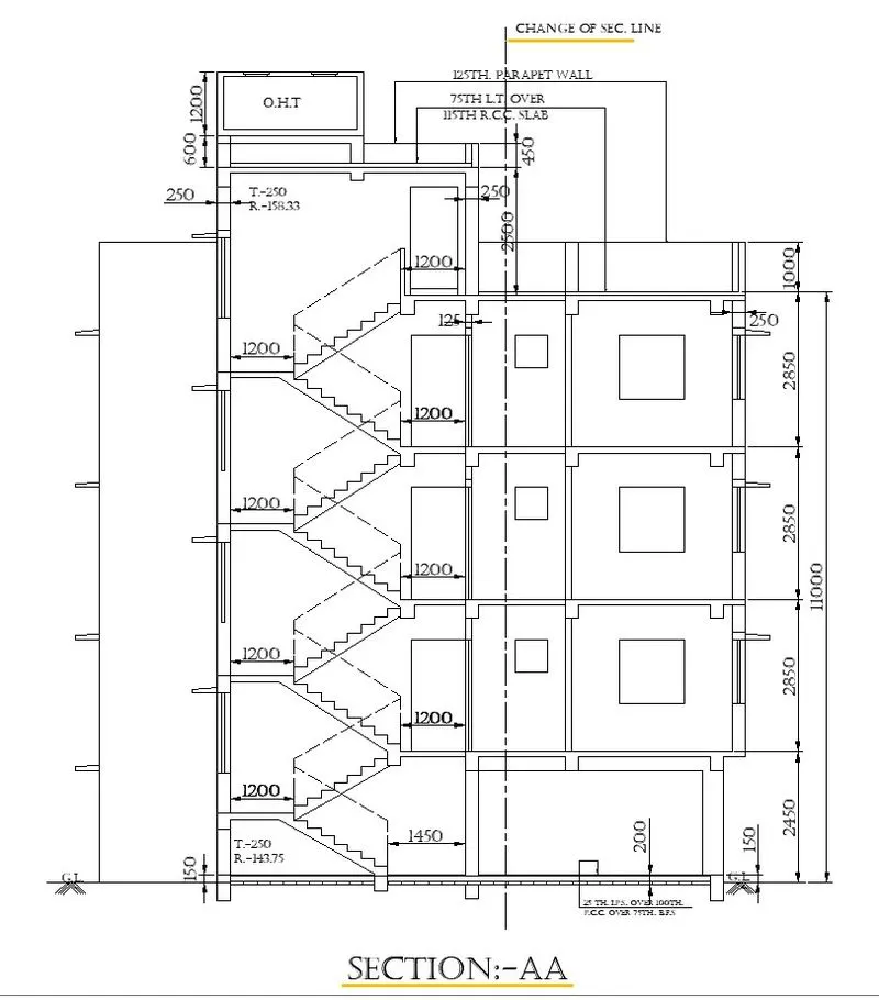
- Enter the Dimension commond and start the linear dimension
- Specify the All needed measurements
- Enter the Mtext commond and start the writing the needed information
- Door and window openings are trim it from projected lines
Step-16
- Creating a section-AA as per given drawing by using AutoCad tools
Procedure: SECTION-BB
Step-17
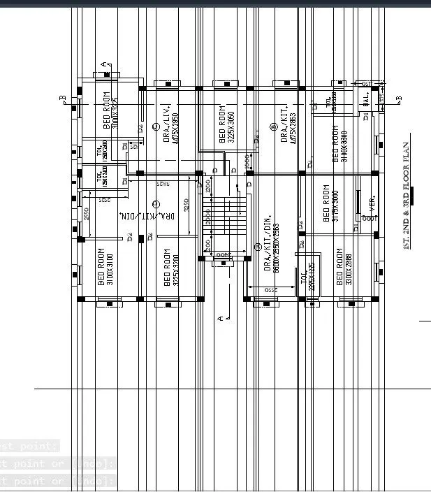
- Change the view of the drawing towards west
- Enter the Xline commond and specify the all the requred points
- L enter and draw the horizontal line
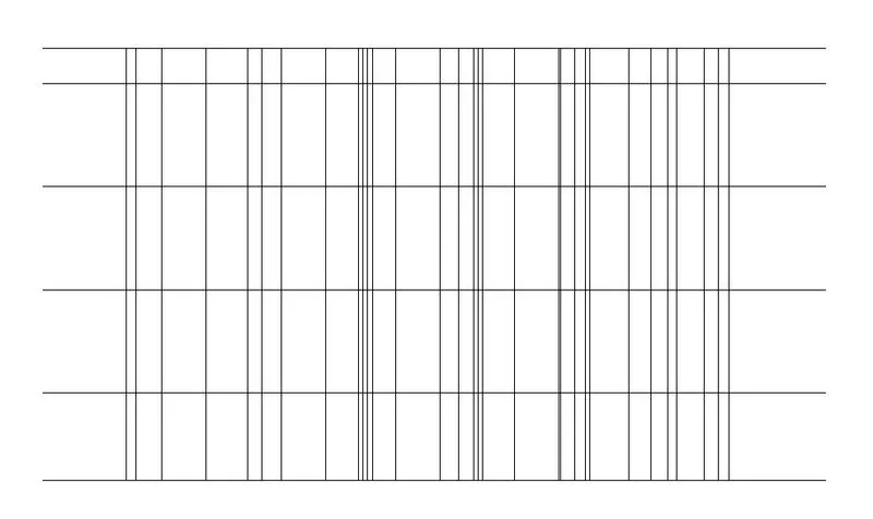
- Offset the horizontal line with 12000 units
- Trim the Unwanted lines

Step-18
- Offset the all the slab top levels from the base which is having vaules of 2450,2850,2850 and 2850 units
- Similarly offset the parapet wall value of 1000 units
Step-19
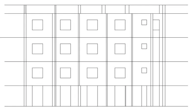
- Trim the unwanted lines
- All window and ventilator lintel level marked as 2100 units
- Sill level marked as 900 units from the slab
- Trim the window and ventilator openings
Step-20
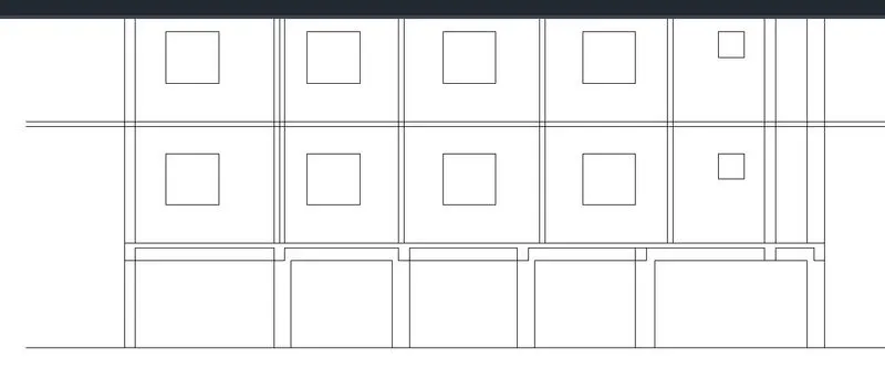
- From the projecton lines columns will be trimed and beam portion is showed in below
Step-21
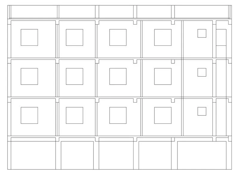
- Offset from slab for beam depth as 400 units and slab thick as 115 units
- Tim the unwanted lines from the beam and slab portions
Step-22
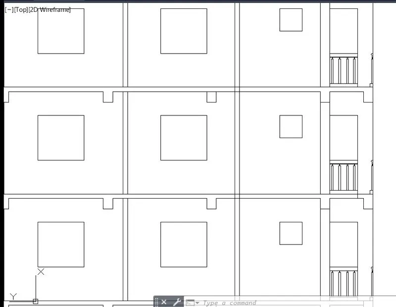
- Creating the balcony SS hand rail upto the sill level 900 units
- Offset the slab top line to 900 units
- Hand rails are drawn by line in between rectangle
- Group it the Hand rail portion and copy it place the required points
Step-23
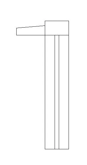
- Enter the rectangle commond
- Specify first point and click on dimension
- Width as 250 units and length as 1200 units
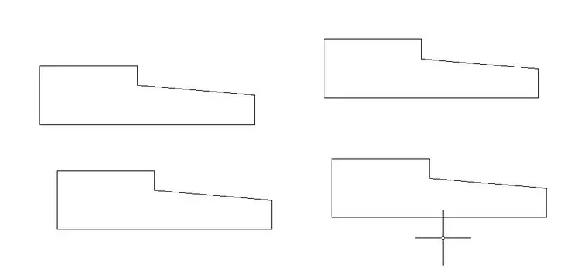
- Sunshade will drawn over the window 150 units and nosing will be 75 units
- Group it
- Copy the required number of windows
- Place required points
Step-24
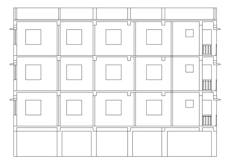
- After placing all window and sunshades
Step-25
- Enter the dimension commond and specify the all the dimensions required
- Enter the Mtext commond and start the reqiured information writing
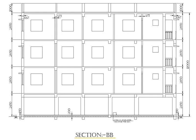
Step-26
- Section-BB is drawn as per given drawing by using AutoCad tools
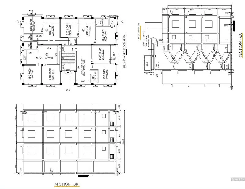
Result: All the drawings are successfully drawn By using AutoCad tools
It includes
- Floor plan
- Section-AA
- Section-BB
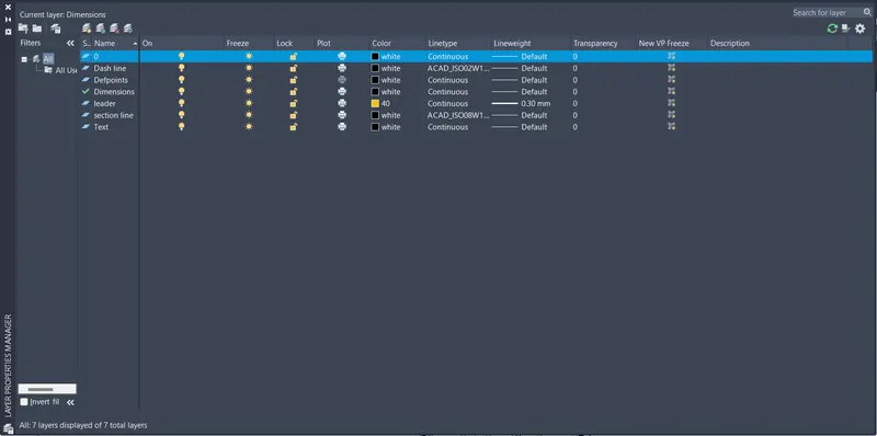
LAYERS :-
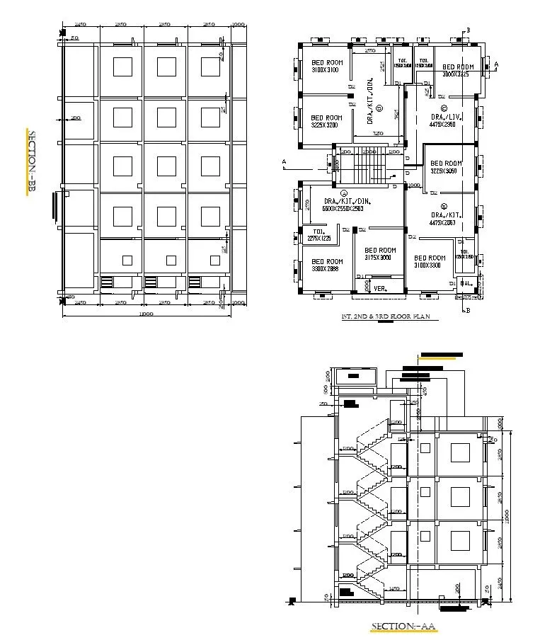
Overview drawing
THANK YOU