Creating a Layout, Section and Elevation with dimensions using AutoCad
1. AIM : To Create the Plan and Sections as shown in the Figures. Use proper dimension techniques
and dimension styles to document the project. Assume the sizes of the doors and windows
as per construction standards. Refer to sections for stair details if required.
- Open the Autocad
- Type unit and selet the decimal unit and precission as 0.0
- Type limits ans specify the lower and upper limits
- Type Z (Zoom) enter and A enter.
- Start for drafting
- All Dimensions are in mm.
COMMAND USED :
- Limits
- Zoom
- Xline
- Line
- Circle (C) command
- X (Explode) Command
- Dimlinear
- Dimstyle
- MLEADER
- Dimcont
- Fillet
- Join
- Object snap
- DT command
- ED command
- MT Command
- Unit command
- LW command
- LT command
- H (Hatch)
- HE (Hatch Edit)
- Offset
- Arc
- Extend command
- Trim command
STEP WISE PROCEDURE :
Step - 1
- Start with line command (L)
- Unit and Grid set 1 and 1
- Enter the xline command : 1,1
- Draw the line in both X and Y axis
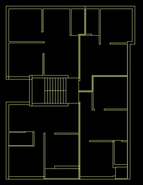
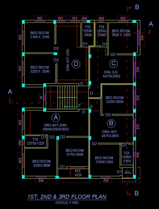
- Draw 1st, 2nd and 3rd floor plan
- Type L enter and specify the point with ortho on draw in X direction-12150 and in Y direction - 16388
- Draw rooms with the help of line and offset command and trim and extend command as per length given in fig.
- Run command offset (O)
- First we draw the bedroom with the size of 3100 x 3100mm
- Next we draw another bedroom with the size of 3225 x 3200
- Next we draw Drawing/kit/din room with the size of 2550 x 3775 x 3250mm
- Next we draw the two toilets with the size 1250 x 2500mm each
- Next we draw dra/liv with the size of 4475mm x 2950mm
- Next we draw bed room in part B with the size of 3225mm x 3050mm
- Next we draw dra/kit with the size of 4475mm x 2863mm
- Next we draw the toilet with the size of 1250 x 2150
- Next we draw another bed room with the size 3100x3300
- Next we draw balcony with size of 1375x1100mm
- Nexe we draw bed room in the Part A with the size of 3175x3000mm
- Next we have to draw the toilet with size of 2275mm x 1225mm
- Next we draw the dra/kit/din room with the size of 6600 x 2550 x 2563mm
- Next we draw the staircase with the size of 3200mm x 2400mm, the tread is 250 and riser 143.75 and 158.33mm
- Trimmed all extra line as as fig. with command (TRIM)
- All works done with different layers shown in different colours
RESULT - Step - 1
Step - 2
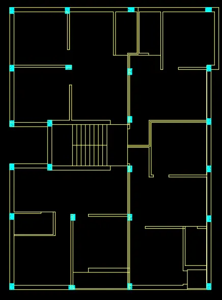
- Next we draw the columns with the size of 250mmX350MM
- The columns are placed where ever they required in the floor plan.
- All works done with different layers shown in different colours
RESULT - Step - 2
Step - 3
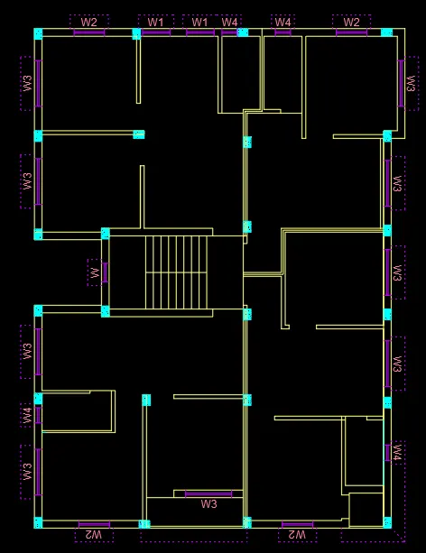
- Next we have to draw the window and doors with the Asumed size are shown below
- W - 600 x 1200mm
- W1- 900 x 1200mm
- W2- 1000 x 1200mm
- W3- 1500 x 1200mm
- W4- 500 x 500mm
- D- 1000 x 2100mm
- D1- 700 x 2100mm
- D2- 900 x 2100mm
- Trimmed all extra line as as fig. with command (TRIM)
- All works done with different layers shown in different colours
RESULT - Step - 3
Step - 4 (Final)
- Finally we indicate the rooms using the MT command
- Dimentions given as per floor plan as given in fig. using Dimlin command
- Also draw the secton lines as given in the fig. indicated A A and B B
- Also indicate the door and windows
- Trimmed all extra line as as fig. with command (TRIM)
- All works done with different layers shown in different colours
FINAL RESULT FOR 1ST, 2ND AND 3RD FLOOR PLAN
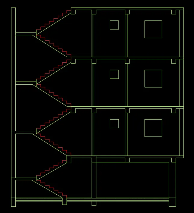
SECTION : AA (Step-1)
- First we have draw the line with length of 8900mm horizontally
- Next again draw the line from the previous line with the length of 11000mm horiziontally from the previousally drawn line.
- Next do the offset to the particular lines with the given offset value
- The inner wall offset are 125mm and outer wall 250mm thickness
- Ground level thickness is 200mm and 150mm
- Next we have draw the windows in their requires places 1st, 2nd and 3rd floors
- Trimmed all extra line as as fig. with command (TRIM)
- All works done with different layers shown in different colours
RESULT - Step - 1
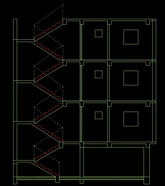
SECTION : AA (Step-2)
- Next we have to draw the stairs with tread 250 and the riser with 143.75 and 158.33mm
- Shown with dashed lines
- Trimmed all extra line as as fig. with command (TRIM)
- All works done with different layers shown in different colours
RESULT - Step - 2
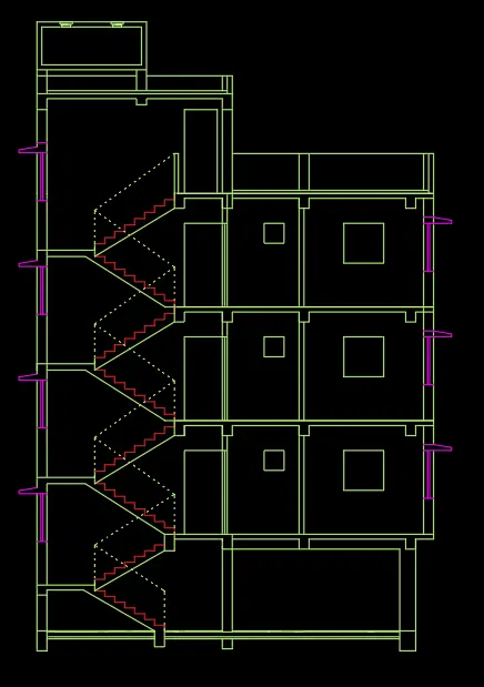
SECTION : AA (Step-3)
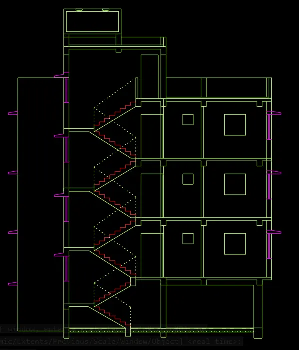
- Next we have to draw the remaining parts parapet wall and water tank (OHT) of the the top of the building
- Next draw the drros at their required places in the 1st, 2nd and 3rd floors
- Trimmed all extra line as as fig. with command (TRIM)
- All works done with different layers shown in different colours
RESULT - Step - 3
SECTION : AA (Step-4)
- Next we have to draw the window and sunshades in their particulars places
- Trimmed all extra line as as fig. with command (TRIM)
- All works done with different layers shown in different colours
RESULT - Step - 4
SECTION : AA (Step-5)
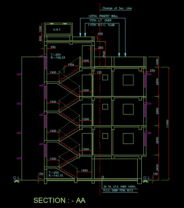
- Next we put the dimensions where ever they are required in the section drawing as shown below
- Finally we have draw the section line in the section plan as shown in fig. below
- Trimmed all extra line as as fig. with command (TRIM)
- All works done with different layers shown in different colours
FINAL RESULT - Step - 5
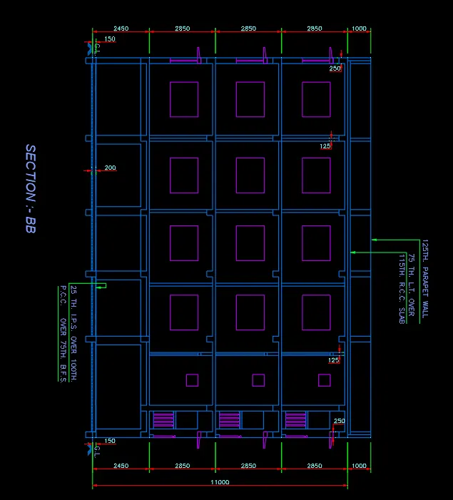
SECTION : BB (Step-1)
- First we have draw the line with length of 11000mm horizontally
- Next we have to draw another line from the previous line vertically with the length of 16388mm
- Next again draw the line from the previous line with the length of 11000mm horiziontally from the previousally drawn line.
- Next do the offset to the particular lines with the given offset value
- The inner wall offset are 125mm and outer wall 250mm thickness
- Ground level thickness is 200mm and 150mm
- Next we have draw the windows in their requires places 1st, 2nd and 3rd floors
- Trimmed all extra line as as fig. with command (TRIM)
- All works done with different layers shown in different colours
RESULT - Step - 1
SECTION : BB (Step-2)
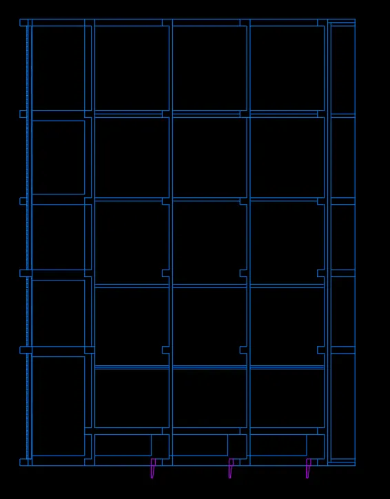
- Next we have draw the sunshades onupside of the window
- And we have to select different layer and colour for different parts in the section plan as shown below
- Trimmed all extra line as as fig. with command (TRIM)
- All works done with different layers shown in different colours
RESULT - Step - 2
SECTION : BB (Step-3)
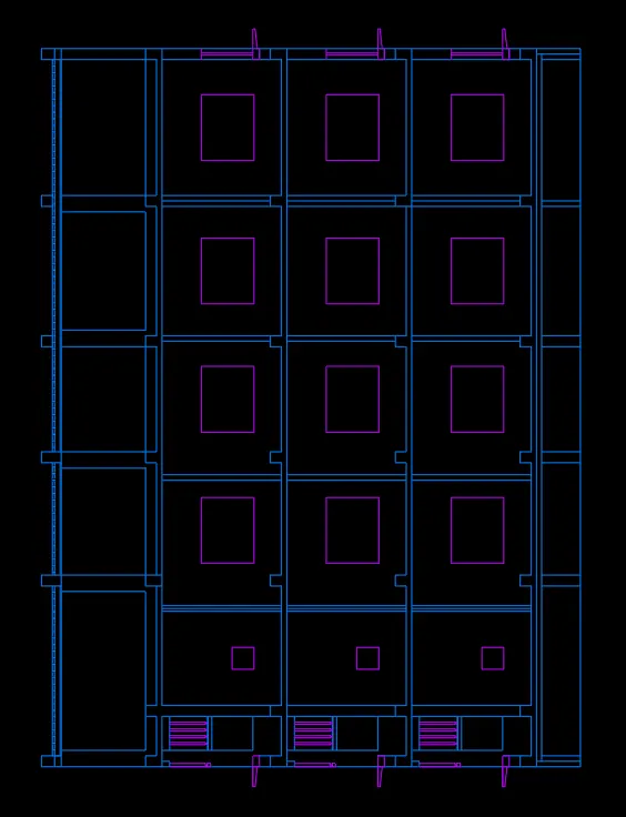
- Next we have put the dimentions where ever they are required
- And write the text to denote the parts in the section using the single text command
- Trimmed all extra line as as fig. with command (TRIM)
- All works done with different layers shown in different colours
FINAL RESULT - Step - 3