Creating a Layout, Section and Elevation with dimensions using AutoCad
Sketch 1:
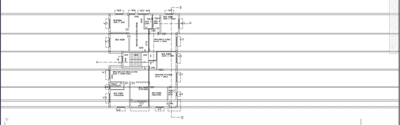
First floor,second floor and third floor plan:
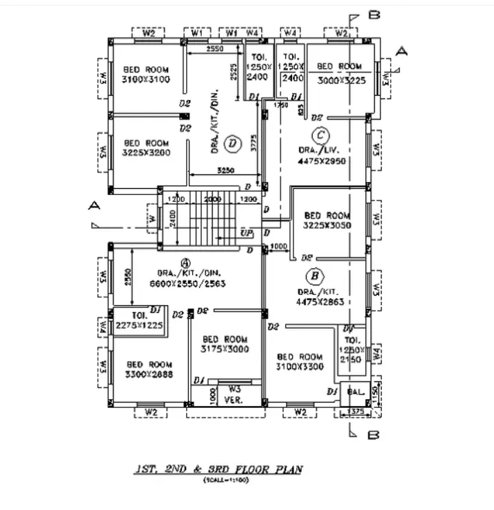
AIM- To draw the Plan of the building by using the AutoCAD software.
INTRODUCTION: This plan can be drawn in the AutoCAD software by using various software tools. Like
Line tool.
Rectangle tool.
Offset tool.
Circle tool.
Copy tool.
Fillet tool.
Trim tool.
Mirror tool.
Array tool.
Extend tool.
Move tool.
Rotate tool.
Dimension tool.
Text tool.
Given dimensions:
External wall: 250 MM
Internal wall: 125 MM
Staircase:
Tread- 250 MM
Riser- 150 MM
Assumed Dimensions:
Windows:
W1: 900 X 1200 MM.
W2: 1200 X 1200 MM.
W3: 1500 X 1200 MM.
W4: 600 X 500 MM.
W: 1002 X 1500
Doors:
D1: 750 X 2000 MM.
D2: 900 X 2000 MM.
D: 1000 X 2000 MM.
PROCEDURE:
- First of all open an AutoCAD software application.
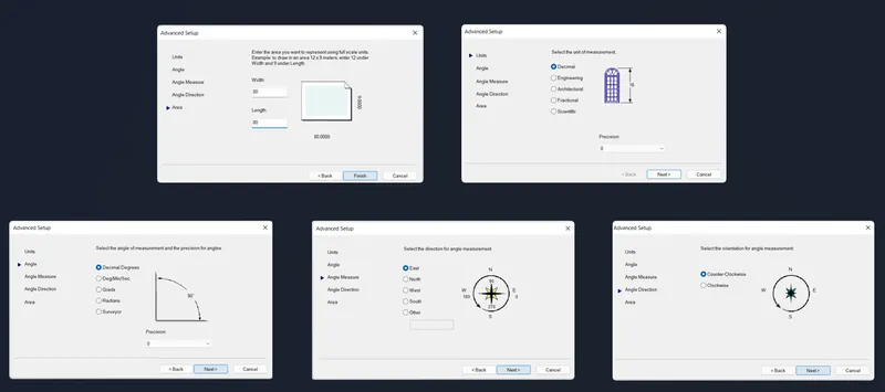
- Then type QNEW in the command line and then press Enter.
- Now select the default setting as Metric.
- Now in an advance setting click OK. and from there set unit as decimal and precision as 0. And then again press Next.
- Now set angle as Decimal angle and presicion as 0,press Next.
- Set angle measure as East and again press Next.
- Set angle direction as Counter-clockwise and press Next.
- Now set area by providing the length and width according to the requirement.
- Here i have provide 80 length and 80 width.
- Now press FINISH. Here the page setup for the drawing is finished. Now we can start the drawing.
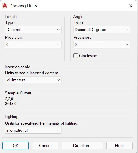
- Here keep the Ortho ON.
- And snap and grid OFF.
- Now type the UN in the command line and then press Enter.
- Set the units as Decimal and precision as 0.
- Page stup is completed.
- Now we will work on the planning of this sketch.
PROCEDURE TO SKETCH THE PLAN:
- First of all type Xline in the command line and then press Enter.
- Put Xline in horizontal and in vertical line to draw the sketch.
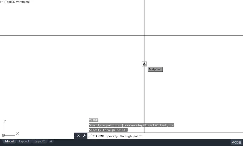
- Now trim the unwanted lines.
- Give the offset of 250 mm to the external wall inside the xline horizontal and vertical line.
- Now give the offset according the requirement of the plan.
- Give offset to each of the vertical lines as well as horizontal lines according to their wall thickness.
- For internal wall give the offset of 125 mm.
- And as for the external wall give the offset of 250 mm.
- Give the offset as per the requirement by using offset command.
- Leave the spaces for the doors as per its dimensions.
- Now using the trim command trim the all unwanted lines from the plan.
- Just type TRIM in the command line and then press Enter.
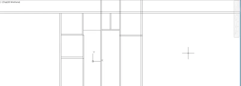
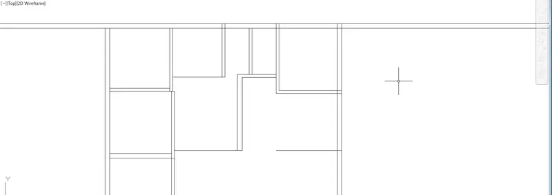
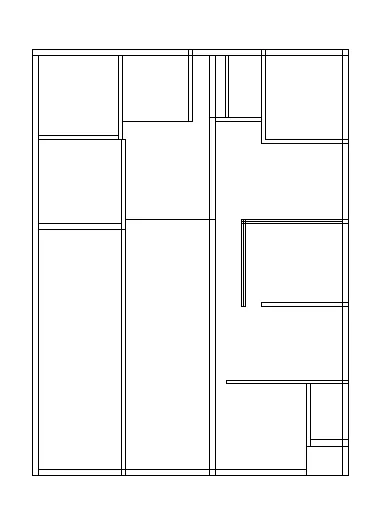
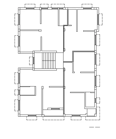
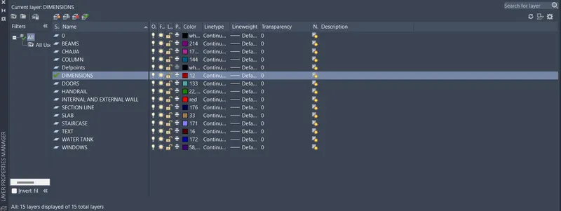
Creating Layers:
- To create the layers for different blocks. Just click on the layer properties.
- A box with different options for creating the layers opens up.
- From there just click on the option NEW LAYER and click.
- Now give it a new name,for example : WALL and press enter.
- Now turn the layer ON.
- Select the colour for that particular layer (WALL), whichever you like.
- Similarly, use this above procedure for creating the different layers which is going to be used in this project.
- The layers which are assigned for this project is shown below:
Windows and doors:
- By using line tool we can create different doors and windows according to their dimensions.
- For doors:
- D - 1000mm.
- D2 - 750mm.
- D3 - 900mm
Here is the figure to show the different doors of different sizes.
- For windows:
- W - 1000mm.
- W1 - 900mm.
- W2 - 1200mm.
- W3 - 1500mm.
- W4 - 700mm.
Columns:
- Now using rectangle command we can create different columns according to their respective sizes.
- Just type REC or rectangle in the command line and then press Enter.
- Specify the first point and then enter.
- Type d in the comment line and then give the length and the width for that column.
- Take length as 250 and width as 350.
- Using hatch command we can hatch the column as shown in the below figure.
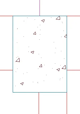
- Now using the copy tool we can copy the column wherever it is required.
- We can rotate the column as per the requirement.
- To do so type rotate in the command line and then press Enter.
- Now select the base point as the centre of the column.
- Specify rotation angle as 90 degree.
- And the column is rotated about 90 degree.
- Place this rotated column wherever is necessary.
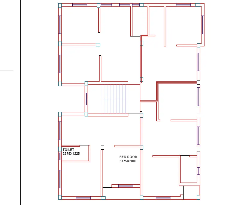
Create the Text:
- To create the text click on the annotation tab then click on the multiline option.
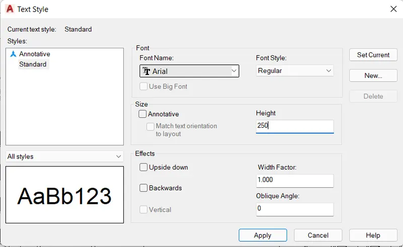
- Then click on the manage text style and then click on NEW option.
- Name the style name according to the project and then OK.
- Take Font style as Arial.
- Give a height of 200mm. And then press set current and then click OK.
- Now use the multiline text and write the text wherever is required in the plan.
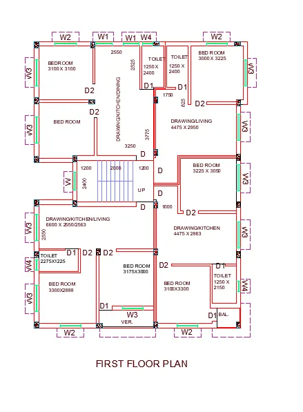
Create annotations:
- For this click on the annotation tab.
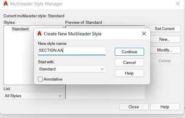
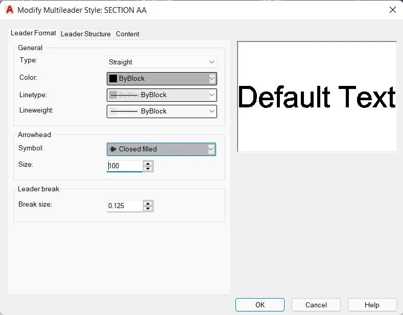
- Then click on the dimension tab manage dimension style.
- Put the required information such as style name etc.
- Select arrowhead sizw as 120.
- Text height should be of 250mm.
- And then select the linear dimension.
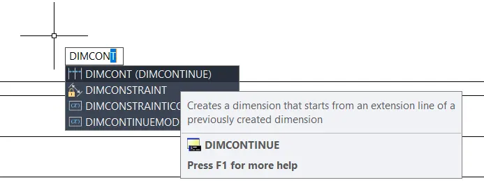
- Then take the continuous dimension option to create a continuous dimensions.
- And provide it wherever is required.
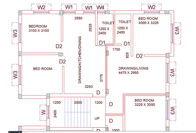
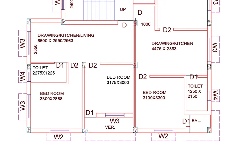
- The plan is ready.
RESULT:
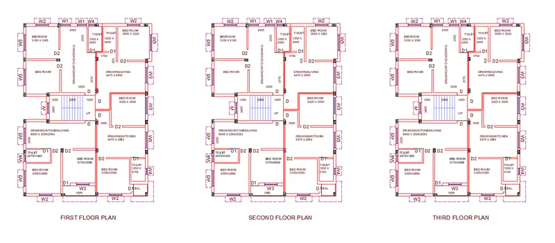
Sketch 2:
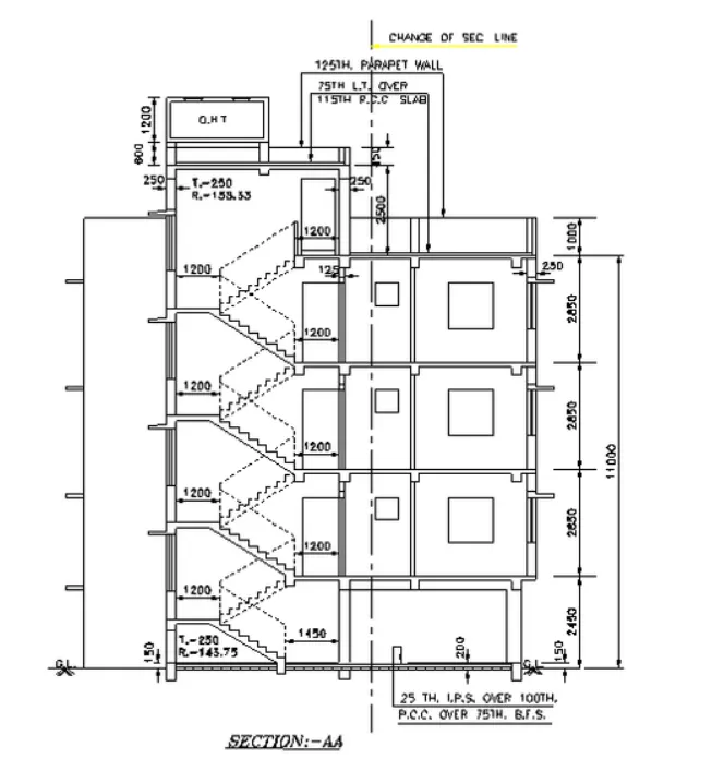
AIM: To draw the section AA of the building by using the AutoCAD software.
PROCEDURE:
- To draw the section AA. I am using xline command.
- And to invoke the xline command just type XLINE in the command line and then press enter.
- Now select vertical from the command line and then press Enter or just type V in the command line and then press Enter.
- Now take the vertical projections along the section line A-A.
- Take a horizontal line using line command and take it as a ground level.
- Now offset the horizontal line at 150 and 125 in the upward direction.
- Now again take a offset of this horrizontal line at 50 below the horizontal line.
- Now offset the top offset at a distance of 2450 keeping the cursor in the upward direction.
- From the last offset take the offset of 2450.
- From the last offset take the offset of 2850.
- From the last offset take the offset of 2850.
- From the last offset take the offset of 2850.
- From the last offset take the offset of 1000.
- Now trim the all unwanted lines using the trim command.
- Give the slab thickness as 125mm by using offset command.
- Change the current layers to Doors and windows layers.
- Now offset the top line of the first floor of 800 to show the sill level.
- Now offset the last line of the first floor of 1200 to give the height of the windows.
- Now trim the all unwanted lines using the trim command.
- From the same above procedure we can draw the other windows at the other floors too i.e W2 and W4.
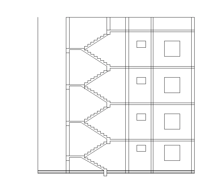
Create staircase( For ground floor):
- Now offset the wall which is near to the staircase with offset distance 1450.
- For first flight:
- Using polyline command we can draw the staircase.
- Type PL or polyline in the command line and then press Enter.
- Select the starting point of the stairs.
- Keep the object snap ON.
- Specify the length of the riser as 143.75 by keeping the cursor in the north direction.
- Now specify the length of the tread as 250 by keeping the cursor in the west direction.
- And now using the copy command we can copy the rise and tread in the specified direction till we reach to the landing.
- For the next set flight i used the same procedure as above.
- Now select the flight which are hidden and click in the properties and select the line type as ACAD_ISO03W100.
- Select the scale as 5.
For the remaining floorrs:
- Take the PL command and draw the staircase.
- Select the starting point of the stairs.
- Keep the object snap ON.
- Specify the length of the riser as 158.33 by keeping the cursor in the north direction.
- Now specify the length of the tread as 250 by keeping the cursor in the west direction.
- And now using the copy command we can copy the rise and tread in the specified direction till we reach to the landing.
- For the next set flight i used the same procedure as above.
- Now select the flight which are hidden and click in the properties and select the line type as ACAD_ISO03W100.
- Select the scale as 5.
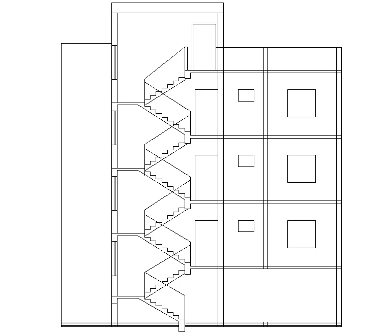
- Using the rectangle command we can draw the doors.
- Specify the first corner point anywhere.
- Now type d as dimension and then press Enter.
- Give the length and width as 1000mm and 2000mm.
- Now copy that rectangle using copy command and then press Enter.
- Copy the rectangle wherever is required as shown in the figure.
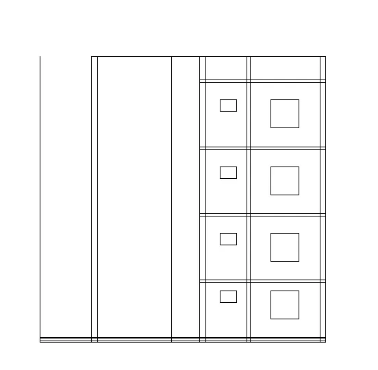
Windows:
- For creating windows use the line command and offset command.
- Provide the window in the section wall.
Create the Text:
- To create the text click on the annotation tab then click on the multiline option.
- Then click on the manage text style and then click on NEW option.
- Name the style name according to the project and then OK.
- Take Font style as Arial.
- Give a height of 200mm. And then press set current and then click OK.
- Now use the multiline text and write the text wherever is required in the plan.
Create annotations:
- For this click on the annotation tab.
- Then click on the dimension tab manage dimension style.
- Put the required information such as style name etc.
- Select arrowhead sizw as 120.
- Text height should be of 250mm..
- And then select the linear dimension.
- Then take the continuous dimension option to create a continuous dimensions.
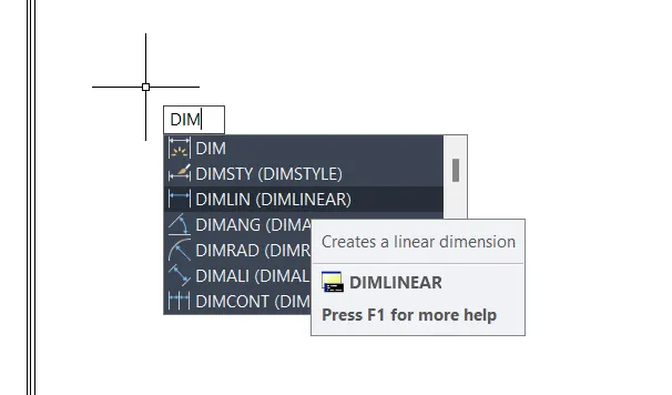
- And provide it wherever is required.
- Section AA is ready.
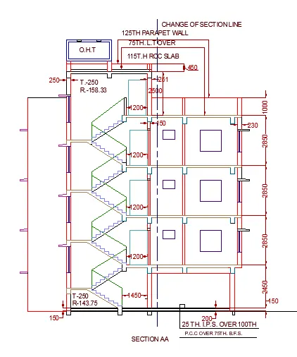
RESULT:
SKETCH 3:
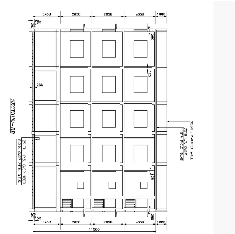
AIM: To draw the section BB of the building by using the AutoCAD software.
PROCEDURE:
- To draw the section BB. I am using xline command.
- And to invoke the xline command just type XLINE in the command line and then press enter.
- Now select horizontal from the command line and then press Enter or just type H in the command line and then press Enter.
- Now take the horizontal projections along the section line B-B.
- Take a vertical line using line command.
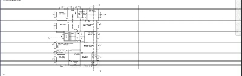
- Now offset the vertical line at 150 and 125 in the upward direction.
- Now again take a offset of this horrizontal line at 50 below the horizontal line.
- Now offset the top offset at a distance of 2450 keeping the cursor in the upward direction.
- From the last offset take the offset of 2450.
- From the last offset take the offset of 2850.
- From the last offset take the offset of 2850.
- From the last offset take the offset of 2850.
- From the last offset take the offset of 1000.
- Now trim the all unwanted lines using the trim command.
- Give the slab thickness as 125mm by using offset command.
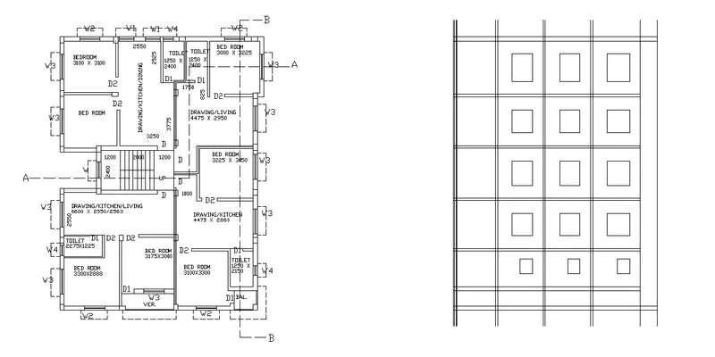
- Change the current layers to Doors and windows layers.
- Now offset the top line of the first floor of 800 to show the sill level.
- Now offset the last line of the first floor of 1200 to give the height of the windows.
- Now trim the all unwanted lines using the trim command.
- From the same above procedure we can draw the other windows at the other floors too i.e W2 and W4.
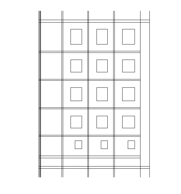
Create the Text:
- To create the text click on the annotation tab then click on the multiline option.
- Then click on the manage text style and then click on NEW option.
- Name the style name according to the project and then OK.
- Take Font style as Arial.
- Give a height of 200mm. And then press set current and then click OK.
- Now use the multiline text and write the text wherever is required in the plan.
Create annotations:
- For this click on the annotation tab.
- Then click on the dimension tab manage dimension style.
- Put the required information such as style name etc.
- Select arrowhead sizw as 120.
- Text height should be of 250mm..
- And then select the linear dimension.
- Then take the continuous dimension option to create a continuous dimensions.
- And provide it wherever is required.
- Section BB is ready.
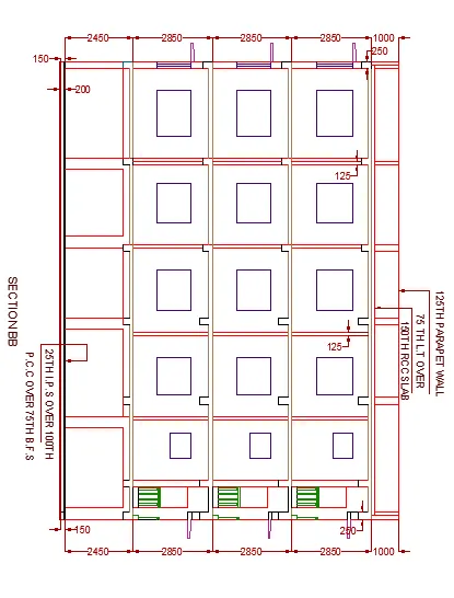
RESULT:
Overall Result:
PLAN:
Sketch 1:
SECTION AA:
Sketch 2:
SECTION BB:
SKETCH 3: