Creating a Floor plan, Footing detail and Isometric view using AutoCad
AIM:
To create the plan, footing detais and isometric view by using autocad.
Default Procedure:
-
- Click on AutoCAD application and open this application
- Initially set the template Imperial ( Feet and inches)and Units(Decimal)
- Then go to application menu -->select new-->creat drawing, to start form scratc.
- Select defaultf setting as Imperial (feet and inches)
- In default setting click on use a wizard and in that advancef setting and unit as decimal and precision as 0.00
- Set Angle as Decimal Degree and precision as 0 and click next
- Set Angle Measure as EAST and Next
- Set Angle Direction as Counter-Clockwise and click Next
- Set Area by provideing Lenght as 12 and Width as 10
- finished
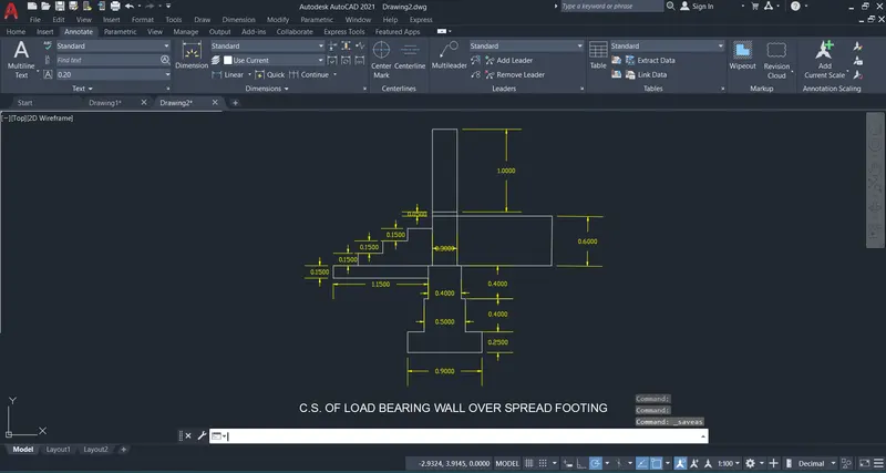
1.C.S Foundation Detalis For Load Bearing Wall Over Spread Footing:
- In this drawing we create a C.S Foundation Detalis For Load Bearing Wall Over Spread Footing
- Now we can see the command used for this drawing as step by step.
PROCEDURE:
- First check the dimension as we start before a line.
- In command bar Enter RECTANGULAR or 'REC' to select rectangular
- In command bar It will ask corner point, so specify it as 2,1
- Next start with a "L"line command.
- Draw a line as per dimension.
- After complete a drawing we need show dimension of Footing
- Click "DIM"command to create a dimension.
- And we use a Snipping Tool to take a screenshot.
- Finally Click Save as to save the picture.
RESULT:
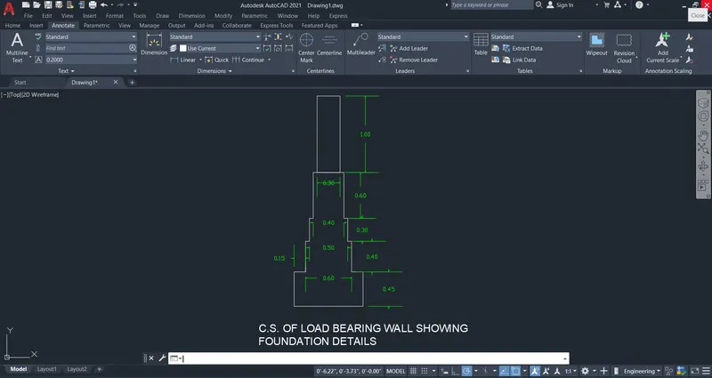
2.CS Foundation Details for Load Bearing Wall:
- In this drawing we create a cs foundation deatails for Load Bearing Wall.
- Now we can see the command used for this drawing as step by step.
PROCEDURE:
- First check the dimension as we start before a line.
- In command bar Enter RECTANGULAR or 'REC' to select rectangular
- In command bar It will ask corner point, so specify it as 2,1
- Next start with a "L"line command.
- Draw a line as per dimension.
- After complete a drawing we need show dimension of Footing
- Click "DIM"command to create a dimension.
- And we use a Snipping Tool to take a screenshot.
- Finally Click Save as to save the picture.
RESULT:
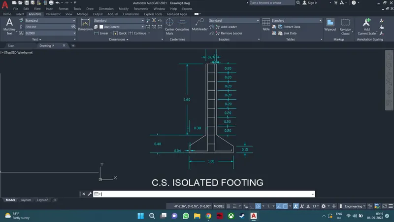
3.C.S Isolated Footing:
- In this drawing we create a C.S Isolated Footing
- Now we can see the command used for this drawing as step by step.
PROCEDURE:
- First check the dimension as we start before a line.
- Next start with a "L"line command.
- Draw a line as per dimension.
- Here we use "F8" orthomod command for draw incliend line.
- use offset "o" of 0.20 for each sections
- After complete a drawing we need show dimension of Footing
- Click "DIM"command to create a dimension.
- And we use a Snipping Tool to take a screenshot.
- Finally Click Save as to save the picture.
Result:
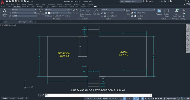
4.Line Diagram of Two Bedroom Buildings:
- In this drawing we create a Line Diagram of Two Bedroom Buildings.
- Now we can see the command used for this drawing as step by step.
PROCEDURE:
- command bar Enter the LINE or 'L' to take line command
- Line specify the first point 1,1
- Line specify the nexp point 0.90 (South)
- Line specify the nexp point 1.00 (East)
- Line specify the nexp point 0.90 (North)
- Line specify the nexp point 4.20 (East)
- Line specify the nexp point 3.60 (North)
- Line specify the nexp point 4.20 (West)
- Line specify the nexp point 0.90 (North)
- Line specify the nexp point 1.00 (West)
- Line specify the nexp point 0.90 (South)
- Line specify the next point 3.60 (West)
- Line specify the next point 3.60 (South) And Enter
- Now take OFFSET command to draw and finished the stair Tread (OFFSET Distance is 0.30)
- Dimensions are used by using dimension command fromt he command bar
- The Line Diagram of a Two Bedroom Building is done.
RESULT:
5.Isometric View Of Stairs:
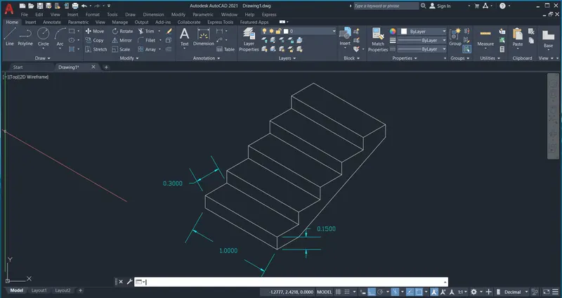
PROCEDURE:
- First type DS in command, this will lead to dialouge box named drafting setting in that snap and grid option change the snap type to isometric
- I have kept snap and grid setting is off
- Choose the line command from the staus bar
- specify the first point 2,1
- Then by distance entry method input the distance one by one and complete the drawing in the isometric plane.
- Now again choose lije option and change to soplane top by pressing the key F5 and then continue entering the distance values.
- similarly comtinue drawing by switching between isoplane left and isoplane right
- Now this drawing is closed by usingline tool connecting between two ends.
- Complete the fugure by dimensioning it.
- Use DIMALIGNED to plot the dimensions of isometric diagram
RESULT:
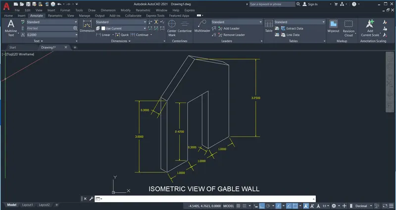
6.Isometric View Of Gable Wall:
- In this drawing we create a Isometric View Of Gable Wall.
- Now we can see the command used for this drawing as step by step.
PROCEDURE:
- First type DS in command, this will lead to dialouge box named drafting setting in that snap and grid option change the snap type to isometric
- I have kept snap and grid setting is off
- Choose the line command from the staus bar
- specify the first point 3,2
- Then by distance entry method input the distanc one by one and co,plete the drawing in the isometric plane.
- First chose isoplane right and enter 3 and press F5 and change to isoplane left and enter 0.3 and change direction to down and enter3.
- Now change to isoplane top and enter 1, then change to isoplane rifht and ente 2,42 and then towards right enter1.00
- Then towards right enter 1 and upwards enter 3 and change to isoplane left and enter 0.3.
- And complete the figure dimensioning it.
- Use DIMALIGNED to plot the dimensions of isometric diagram
RESULT: