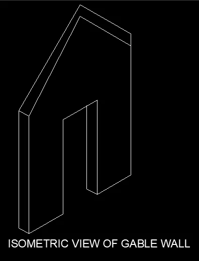
Creating a Floor plan, Footing detail and Isometric view using AutoCad
Commands used in this challenge:
- Line
- Polyline
- Rectangle
- Fillet
- Chamfer
- Trim
- Offset
- Isometric view
- Copy
- Move
- Dimlinear
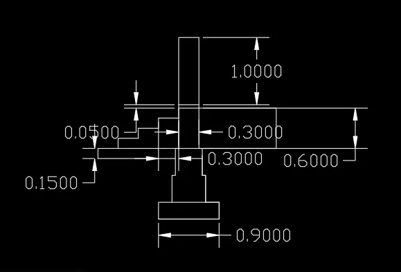
1. Draw C1 figure using AutoCAD.
Aim: Draw C1 of C.S (Cross section) of load bearing wall over spread footing.
Introduction: Wall footing is type of footing which used to support walls both structural and non-structural. This footing takes load from walls of structure and transferred such that the load bearing capacity of the soil does not reduced. It also maintains sufficient safety against overturning and sliding and also avoids excessive settlement.
Procedure:-
- Select Line from toolbar.
- Specify first point as 7,1
- Specify next point as @0.9,0
- Specify next point as @0,0.25
- Specify next point as @-0.2,0
- Specify next point as @0,0.4
- Specify next point as @-0.05,0
- Specify next point as @0,0.4
- Specify next point as @-0.05,0
- Specify next point as @0,0.6
- Specify next point as @-0.3,0
- Specify next point as @0,-0.6
- Specify next point as @-0.05,0
- Specify next point as @0,-0.4
- Specify next point as @-0.05,0
- Specify next point as @0,-0.4
- Specify next point as @-0.2,0
- Specify next point as @0,-0.25
- Then press Enter.
- Select Line from toolbar.
- Select required point in the Column.
- Specify next point as @0.90,0
- Then press Enter.
- Select required point in the Column.
- Specify next point as @0,-0.15
- Specify next point as @-1.15,0
- Specify next point as @0,0.15
- Specify next point as @0.30,0
- Specify next point as @0,0.15
- Specify next point as @0.30,0
- Specify next point as @0,0.15
- Specify next point as @0.30,0
- Specify next point as @0,0.15
- Specify next point as @0,30,0
- Then press Enter.
- Select required point in the Column.
- Specify next point as @0,0.05
- Specify next point as @0,-0.3
- Specify next point as @0,-0.05
- Then press Enter.
- Select required point in the Column.
- Specify next point as @0,1
- Specify next point as @-0.3,0
- Specify next point as @0,-1
- Then press Enter.
- After that type DIMLINEAR in the command bar for placing dimensions of the drawn figure.
- All dimensions are in meter.
RESULT:-
C.S OF LOAD BEARING WALL OVER SPREAD FOOTING
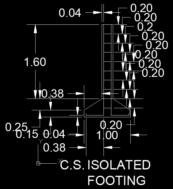
2. Draw C2 figure using AutoCAD
Aim:- To draw the figure of C2 of C.S. of isolated footing.
Introduction :- Isolated footing is a type of footing which is placed at shallow depth and supports one column of the building. It is an independent footing designed to support an independent column. The shape of column can be rectangular, square or circle. Based on the cross-sectional shape they are classified as pad footing, stepped footing and slope footing.
Procedure :-
Type “rec” in command prompt or select rectangle from toolbar
- Specify first corner point: take 1,1 then enter
- Specify other corner point: @1,0.4 then enter
Type “chamfer” in command prompt or select chamfer from modify toolbar
- Specify first chamfer distance: Type 0.38 then enter
- Specify second chamfer distance: Type 0.25 then enter
- Select first line: select left horizontal part of rectangle
- Select second line: select left vertical line of rectangle then enter
- Select first line: select right horizontal part of rectangle
- Select second line: select right vertical line of rectangle then enter
Type “PL” in command prompt or select line from toolbar
- Specify first point: click rectangles top at the chamfer cutting point
- Specify other point: @1.60<90 then enter
- Specify other point: @0.24<0 then enter
- Specify other point: @1.60<270 then enter
Type “PL” in command prompt or select line from toolbar
- Specify first point: click at the top let of the column
- Specify other point: @0.04<0 then enter
- Specify other point: @1.96<270 then enter
- Specify other point: @0.38<180 then enter
- Specify other point: @0.03<90 then enter
Type “PL” in command prompt or select line from toolbar
- Specify first point: click at the top right of the column
- Specify other point: @0.04<180 then enter
- Specify other point: @1.96<270 then enter
- Specify other point: @0.38<0 then enter
- Specify other point: @0.03<90 then enter
Type “L” or line then enter
- Specify first point: on snap or click F3 and click on the top polyline point at the top rectangle
Type “O” in command prompt or offset from modify toolbar
- Specify offset distance: 0.2 then enter
- Select object to offset: select the line at the top and bring curser down and click to offset that line
- Select the last offset line and bring curser down and click to offset that line
- Select the last offset line and bring curser down and click to offset that line
- Select the last offset line and bring curser down and click to offset that line
- Select the last offset line and bring curser down and click to offset that line
- Select the last offset line and bring curser down and click to offset that line
- Select the last offset line and bring curser down and click to offset that line
- Select the last offset line and bring curser down and click to offset that line
- Select the last offset line and bring curser down and click to offset that line
- Tap esc to close the offset command
After that use “DIMLIN” for the dimensions all of the drawn figure
- All dimensions are in meters.
RESULT :-
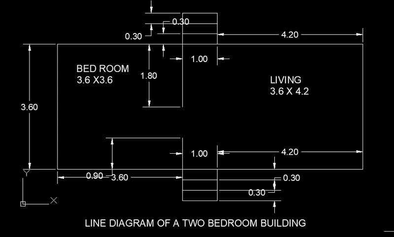
3. Draw C3 figure using AutoCAD
AIM :- Draw the figure C3 of C.S. of line diagram of a two-bedroom building.
INTRODUCTION :- Line drawing are drawings with details of dimensions and components of building. Two-bedroom building consists of 1x bedroom, 1x living room and steps in both directions.
PROCEDURE :-
Type “rec” in command prompt or select rectangle from the draw toolbar
- Specify first point: 1,1 and then enter
- Specify other corner point: @8.80,3.60 then enter
Type “L” in command prompt or select line from toolbar
- Specify first point: click on bottom left of the rectangle
- Specify other point: @3.60<0 then enter
- Specify other point: @0.90<90 then enter
Type “L” in command prompt or select line from toolbar
- Specify first point: click on top left of the rectangle
- Specify other point: @3.60<0 then enter
- Specify other point: @1.80<270 then enter
Type “rec” in command prompt or select rectangle from the draw toolbar
- Specify first point: click on bottom line at cross point
- Specify other corner: @1,0.30 then enter
Type “CO” in command prompt or select copy from modify tollbar
- Select the rectangle ate the middle of bottom line then enter
- Specify the base point: select the base of that rectangle
- Then using of curser copy and enter
- Then using of curser copy and enter
- Then esc to close the copy command
Type “rec” in command prompt or select rectangle from the draw toolbar
- Specify first point: click on bottom line at cross point
- Specify other corner: @1,0.30 then enter
Type “CO” in command prompt or select copy from modify tollbar
- Select the rectangle ate the middle of top line then enter
- Specify the base point: select the base of that rectangle
- Then using of curser copy and enter
- Then using of curser copy and enter
- Then esc to close the copy command
- After that use “DIMLIN” for the dimensions all of the drawn figure
Type “MT” or select text from toolbar and write left side BED ROOM 3.6 x 3.6 and right side LIVING ROOM 3.6 x 4.2
- All dimensions are in meter.
RESULT :-
4. Draw C4 figure using AutoCAD
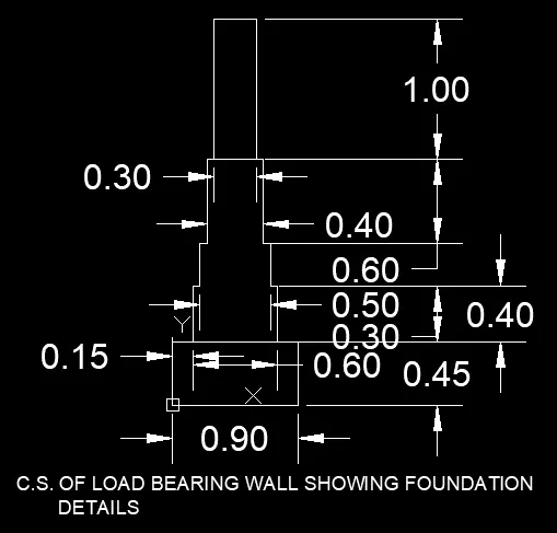
AIM :- To draw the figure C4 of C.S. of load bearing wall showing foundation detail.
INTRODUCTION :- Load bearing wall are wall which take loads from the beam, columns and also slab and transfers the foundation below them.
PROCEDURE :-
Type “REC” in command prompt or select rectangle from toolbar
- Specify first point: 0,0 then enter
- Specify other corner point: @0.90,0.45 then enter
Type “PL” in command prompt or select from toolbar
- Specify start point: click top left corner of the rectangle
- Specify next point: @0.15<0 then enter
- Specify next point: @0.40<90 then enter
- Specify next point: @0.05<0 then enter
- Specify next point: @0.30<90 then enter
- Specify next point: @0.05<0 then enter
- Specify next point: @0.60<90 then enter
- Specify next point: @0.40<0 then enter
- Specify next point: @0.60<270 then enter
- Specify next point: @0.05<0 then enter
- Specify next point: @0.30<270 then enter
- Specify next point: @0.05<0 then enter
- Specify next point: @0.40<270 then enter
Type “L” in command prompt or select from toolbar
- Specify first point: click on the top left of the column
- Specify next point: @0.05<0 then enter
Type “REC” in command prompt or select from toolbar
- Specify first point: click on the end point of last line draw at the top of column
- Specify other corner point: @0.30,1 then enter
- After that use “DIMLIN” for the dimensions all of the drawn figure
- All dimensions are in meter.
RESULT :-
5. Draw C5 figure using AutoCAD
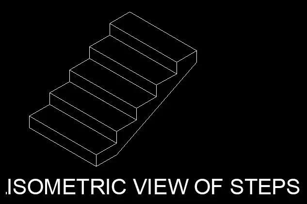
AIM :- To draw the figure C5 of isometric view of steps
INTRODUCTION :- Steps or stairs is a component of bearing, which are used to connect different floor or floor at higher level. It has a horizontal component called thread and a vertical component called rise. A series of threads and rises from a staircase.
PROCEDURE :-
Go to grid and snap setting and turn on isometric view.
Press F5 to change the direction of the isometric view to isoplane left or change direction in status bar to isoplane right
Turn on “orthomode”
Type “L” in command prompt or select from toolbar
- Specify first point: 1,1 then enter
- Specify next point: place the curser to right of first point then type 1 then enter
- Specify next point: place the curser to top of last point then type 0.15 then enter
- Specify next point: place the curser to left of last point then type 1 then enter
- Specify next point: C then enter or close option
Type “L” in command prompt or select from toolbar
- Specify first point: click on the top right corner of the rectangle
- Specify next point: place the curser to right of that point then type 0.30 then enter
- Specify next point: place the curser to top of that point then type 1 then enter
- Specify next point: place the curser to left of that point then type 0.30 then enter
Type “CO” in command prompt or select copy from modify tollbar
- Select the steps (as object) then enter
- Specify the base point: select the base of that
- Then using of curser copy and enter
- Then using of curser copy and enter
- Then using of curser copy and enter
- Then using of curser copy and enter
Type “L” in command prompt or select from toolbar
- Specify first point: click at the end of top steps rectangle
- Specify next point: place the curser to top then type 0.15 then enter
Type “L” in command prompt or select from toolbar
- Specify first point: click at the end of base steps rectangle
- Specify next point: place the curser to top then type 0.30 then enter
- Specify next point: place the curser to right of that point then “C” or close to the top of the end line.
- All dimensions are in meter.
RESULT :-
6. Draw C6 figure using AutoCAD
AIM :- To draw the figure of C6 of isometric view of gable wall.
INTRODUCTION :- A wall with triangular portion between the intersecting of roof pitches is called gable wall. The shape of the gable and how it is detailed depends on the structural system used, which reflects climate, material availability and aesthetic concerns. The combination of wall and the gable at the top is referred to as the gable wall or gable end. While a front gabled building faces the street with its gable, a side gable building faces it with its gutter, meaning the ridge is parallel to the street.
PROCEDURE :-
Go to grid and snap setting and turn on isometric view.
Press F5 to change the direction of the isometric view to isoplane left or change direction in status bar to isoplane right
Turn on “orthomode”
Type “L” in command prompt or select from toolbar
- Specify first point: 1,1 then enter
- Specify next point: place the curser to right of first point then type 1 then enter
- Specify next point: place the curser to top of last point then type 2.42 then enter
- Specify next point: place the curser to right of last point then type 1 then enter
- Specify next point: place the curser to left of last point then type 1 then enter
- Specify next point: place the curser to top of last point then type 3 then enter
Type “L” in command prompt or select from toolbar
- Specify first point: click on the starting point of base
- Specify next point: place the curser to left of last point then type 3 then enter
Type “L” in command prompt or select from toolbar
- Specify first point: click on the right point of door at the bottom
- Specify next point: place the curser to left of last point then type 0.30 then enter
- place the curser to top of last point then type 2.42 then enter
Type “L” in command prompt or select from toolbar
- Specify first point: click on the starting corner point of base
- Specify next point: place the curser to left of last point then type 0.15 then enter
- Specify next point: place the curser to top of last point then type 3 then enter
- Specify next point: place the curser to left of last point then type 0.15 then enter
Type “L” in command prompt or select from toolbar
- Specify first point: select the mid point of the top of the door
- Specify next point: place curser to top of that line and make line randomly to get exact center top
Type “L” in command prompt or select from toolbar
- Specify first point: click on the top of left line
- Specify next point: place the curser to right of last point the connect with Streat line of door center
Type “L” in command prompt or select from toolbar
- Specify first point: click on the top of right line
- Specify next point: place the curser to right of last point the connect with Streat line of door center
Type “TRIM” or select from modify toolbar and trim those unwanted line
- All dimensions are in meter.
RESULT :-