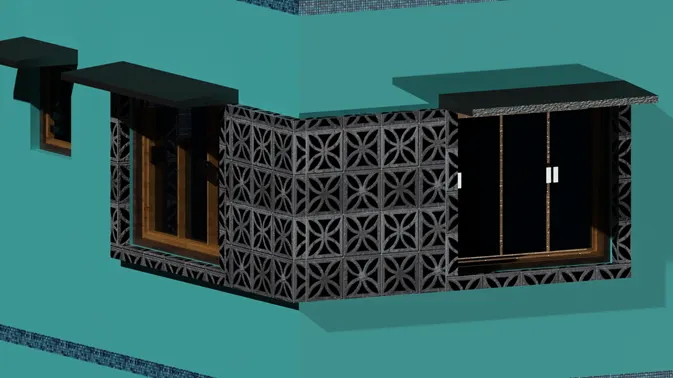
Creating a 3D rendered model for a Residential Building in AutoCad
Project 2 (AutoCAD)
Submitted by Kanala Rahul Reddy
Commands Used in this challenge
- Line
- Xline
- Polyline
- Rectangle
- Circle
- Arc
- Trim
- Move
- Offset
- Hatch
- Layer
- Match Prop
- Multileader
- Fillet
- Copy
- Explode
- Dimlinear
- Dimcontinue
- Dim break
- Dim update
- Hide pallets (POFF)
- Show pallets (PON)
- Extrude
- Boundary/BO
- Region
- Sweep
- Matbrowseopen
- Material Mapping
- Create light
- 3D Orbit
- 3D Rotate
Aim: To draw a 3D Rendered view of a Residential Building
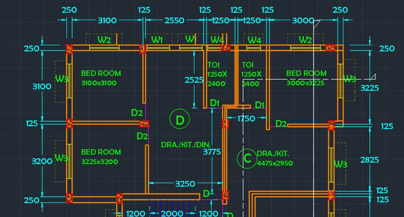
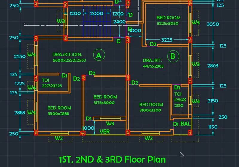
Introduction: Initially a floor plan is made as per challenge 7 of AutoCAD. The floor plan is of an apartment building with the same plan for the 1st, 2nd, and 3rd floors. Each floor consists of four houses, three two-bedroom flats and one single bedroom flat each with kitchen and living room. Each flat has only one common bathroom. Stairs connect all the floors. Stair dimensions are taken from the stair section view. The top two flats are given as flat C and flat D respectively. The section views AA and BB are drawn using projection lines from the plan drawing. Dimensions and text are placed accordingly. The dimensions of doors and windows are assumed as follows
- Main Door or D as 1000mm X 2200mm
- Door 1 or D1 as 700mm X 2000mm
- Door 2 or D2 as 800mm X 1750mm
- Window 1 or W1 as 1000mm X 1200mm
- Window 2 or W2 as 1300mm X 1200mm
- Window 3 or W3 as 1500mm X 1200mm
- Window 4 or W4 as 600mm X 700mm
3D view of the residential building is drawn changing drafting and annotation settings to “3D Modelling Advanced”. Using command like region, boundary 3D faces are created, which are extruded to give 3D view to the structure. Components/ Furniture of the house is created separately and then added to the structure. Super structure of 4 floors is then created.
Rendering of the residential building is done using “Material browser” command in Visualize Tab. Various rendering views are to be made
Procedure:
Open AutoCAD
In Start-up settings start from scratch select metric (Meter)
Open grid and snap settings
- Change snap and grid spacing to 100
- Change major line every grid line to 10
- Turn off adaptive grid
Type ‘un’ in command box and press enter
Change units’ type to decimal and precision to 0.00 and insertion scale to millimeters
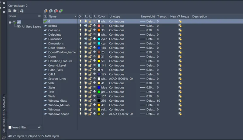
Step 1: Creating Layers
Open Layer properties and create new layers by clicking on new layer or right-click on any layer and select a new layer to create a new layer
Layers are created as follows
Step 2: Creating Flat C and D
Type line in command box and press enter
- Specify a point or [Hor: Ver: Ang: Bisect: Offset]: Click on hor and select any point on the screen
Type xline in command box and press enter
- Specify a point or [Hor: Ver: Ang: Bisect: Offset]: Click on ver and select any point on the horizontal xline
Type ‘o’ or offset and press enter or click offset from the modify tool bar
- Specify offset distance: Type 250 and press enter
- Select object to offset: Select horizontal xline and click on bottom
- Select object to offset: Select vertical xline and click on right
Type ‘o’ or offset and press enter or click offset from the modify tool bar
- Specify offset distance: Type 3100 and press enter
- Select object to offset: Select the vertical offset xline of wall thickness and click on right
Type ‘o’ or offset and press enter or click offset from the modify tool bar
- Specify offset distance: Type 125 and press enter
- Select object to offset: Select last offset to give wall thickness and click on right
Type ‘o’ or offset and press enter or click offset from the modify tool bar
- Specify offset distance: Type 2550 and press enter
- Select object to offset: Select the last vertical offset line and click on right
Type ‘o’ or offset and press enter or click offset from the modify tool bar
- Specify offset distance: Type 125 and press enter
- Select object to offset: Select last offset to give wall thickness and click on right
Type ‘o’ or offset and press enter or click offset from the modify tool bar
- Specify offset distance: Type 1250 and press enter
- Select object to offset: Select the last vertical offset line and click on right
Type ‘o’ or offset and press enter or click offset from the modify tool bar
- Specify offset distance: Type 125 and press enter
- Select object to offset: Select last offset to give wall thickness and click on right
Type ‘o’ or offset and press enter or click offset from the modify tool bar
- Specify offset distance: Type 1250 and press enter
- Select object to offset: Select the last vertical offset line and click on right
Type ‘o’ or offset and press enter or click offset from the modify tool bar
- Specify offset distance: Type 125 and press enter
- Select object to offset: Select last offset to give wall thickness and click on right
Type ‘o’ or offset and press enter or click offset from the modify tool bar
- Specify offset distance: Type 3000 and press enter
- Select object to offset: Select the last vertical offset line and click on right
Type ‘o’ or offset and press enter or click offset from the modify tool bar
- Specify offset distance: Type 250 and press enter
- Select object to offset: Select last offset to give wall thickness and click on right
Trim off outer portions and extra portions as shown in the figure
Type ‘o’ or offset and press enter or click offset from the modify tool bar
- Specify offset distance: Type 3100 and press enter
- Select object to offset: Select the horizontal offset xline of wall thickness and click on bottom
Type ‘o’ or offset and press enter or click offset from the modify tool bar
- Specify offset distance: Type 125 and press enter
- Select object to offset: Select horizontal offset xline to give wall thickness and click on bottom
Type ‘o’ or offset and press enter or click offset from the modify tool bar
- Specify offset distance: Type 3200 and press enter
- Select object to offset: Select the last offset line of wall thickness and click on bottom
Type ‘o’ or offset and press enter or click offset from the modify tool bar
- Specify offset distance: Type 250 and press enter
- Select object to offset: Select last offset line to give wall thickness and click on bottom
Draw a line connecting the two bathrooms
Type ‘o’ or offset and press enter or click offset from the modify tool bar
- Specify offset distance: Type 2400 and press enter
- Select object to offset: Select the line drawn above of wall thickness and click on bottom
Type ‘o’ or offset and press enter or click offset from the modify tool bar
- Specify offset distance: Type 125 and press enter
- Select object to offset: Select last offset line to give wall thickness and click on bottom
Type ‘o’ or offset and press enter or click offset from the modify tool bar
- Specify offset distance: Type 3775 and press enter
- Select object to offset: Select the last offset line of wall thickness and click on bottom
Type ‘o’ or offset and press enter or click offset from the modify tool bar
- Specify offset distance: Type 250 and press enter
- Select object to offset: Select the last offset line and give wall thickness and click on bottom
Extend that last two offset lines till the left most wall edge, so that it can be trimmed off later
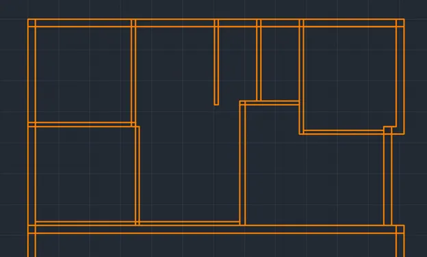
Draw a line at the inner top edge of bedroom of flat C
Type ‘o’ or offset and press enter or click offset from the modify tool bar
- Specify offset distance: Type 3225 and press enter
- Select object to offset: Select the line drawn earlier and click on bottom
Type ‘o’ or offset and press enter or click offset from the modify tool bar
- Specify offset distance: Type 125 and press enter
- Select object to offset: Select the last offset line and click on bottom
Type ‘o’ or offset and press enter or click offset from the modify tool bar
- Specify offset distance: Type 2950 and press enter
- Select object to offset: Select the last offset line and click on bottom
Type ‘o’ or offset and press enter or click offset from the modify tool bar
- Specify offset distance: Type 4475 and press enter
- Select object to offset: Select the left edge of the living room in flat C and click on right
Adjust the wall of flat C living room as shown in figure
The final figure with door openings and windows is as follows
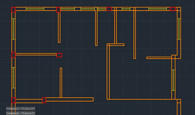
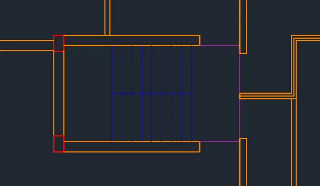
Creating stairs, flat A and flat B
Stairs
Type ‘o’ or offset and press enter or click offset from the modify tool bar
- Specify offset distance: Type 2400 and press enter
- Select object to offset: Select the bottom outer wall edge of flat D and click on bottom
Type ‘o’ or offset and press enter or click offset from the modify tool bar
- Specify offset distance: Type 250 and press enter
- Select object to offset: Select the last offset line and click on bottom
Using line command draw lines connecting the edges of columns
Using line command draw a line at the left edge of stair way
Type ‘o’ or offset and press enter or click offset from the modify tool bar
- Specify offset distance: Type 1200 and press enter
- Select object to offset: Select the line drawn earlier and click on left
Type ‘o’ or offset and press enter or click offset from the modify tool bar
- Specify offset distance: Type 2000 and press enter
- Select object to offset: Select the line drawn earlier and click on left
Type ‘o’ or offset and press enter or click offset from the modify tool bar
- Specify offset distance: Type 250 and press enter
- Select object to offset: Select the last offset line and click on right
- Select object to offset: Select the last offset line and click on right
- Select object to offset: Select the last offset line and click on right
- Select object to offset: Select the last offset line and click on right
- Select object to offset: Select the last offset line and click on right
- Select object to offset: Select the last offset line and click on right
- Select object to offset: Select the last offset line and click on right
Draw a line connecting midpoints of the stairs
Using line command draw the left wall concerning stairs
Change the layer to stairs layer in the layer dropdown
Flat A and B
Using line command draw the top wall of flat B starting from the middle of stairway
Offset the wall line drawn with 250 mm to bottom
Type ‘o’ or offset and press enter or click offset from the modify tool bar
- Specify offset distance: Type 3050 and press enter
- Select object to offset: Select the last offset line at top and click on bottom
Type ‘o’ or offset and press enter or click offset from the modify tool bar
- Specify offset distance: Type 125 and press enter
- Select object to offset: Select the last offset line and click on bottom
Type ‘o’ or offset and press enter or click offset from the modify tool bar
- Specify offset distance: Type 2863 and press enter
- Select object to offset: Select the last offset line at top and click on bottom
Type ‘o’ or offset and press enter or click offset from the modify tool bar
- Specify offset distance: Type 125 and press enter
- Select object to offset: Select the last offset line and click on bottom
Draw a line using line command at the right wall edge of top bedroom of flat B on vertical x line
Type ‘o’ or offset and press enter or click offset from the modify tool bar
- Specify offset distance: Type 3225 and press enter
- Select object to offset: Select the line drawn earlier at right wall and click on left
Type ‘o’ or offset and press enter or click offset from the modify tool bar
- Specify offset distance: Type 125 and press enter
- Select object to offset: Select the last offset line and click on left
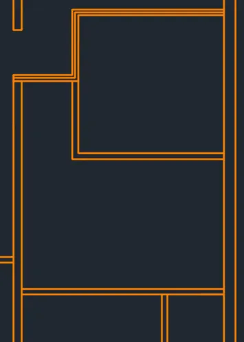
Type ‘o’ or offset and press enter or click offset from the modify tool bar
- Specify offset distance: Type 2563 and press enter
- Select object to offset: Select the bottom edge of stair way and click on bottom
Type ‘o’ or offset and press enter or click offset from the modify tool bar
- Specify offset distance: Type 125 and press enter
- Select object to offset: Select the last offset line and click on bottom
Type ‘o’ or offset and press enter or click offset from the modify tool bar
- Specify offset distance: Type 3000 and press enter
- Select object to offset: Select the bottom edge of stair way and click on bottom
Type ‘o’ or offset and press enter or click offset from the modify tool bar
- Specify offset distance: Type 250 and press enter
- Select object to offset: Select the last offset line and click on bottom
Type ‘o’ or offset and press enter or click offset from the modify tool bar
- Specify offset distance: Type 2550 and press enter
- Select object to offset: Select the bottom edge of wall left of stairway and click on bottom
Type ‘o’ or offset and press enter or click offset from the modify tool bar
- Specify offset distance: Type 125 and press enter
- Select object to offset: Select the last offset line and click on bottom
Trim off extra portions
Type ‘o’ or offset and press enter or click offset from the modify tool bar
- Specify offset distance: Type 1225 and press enter
- Select object to offset: Select the last offset line and click on bottom
Type ‘o’ or offset and press enter or click offset from the modify tool bar
- Specify offset distance: Type 125 and press enter
- Select object to offset: Select the last offset line and click on bottom
Type ‘o’ or offset and press enter or click offset from the modify tool bar
- Specify offset distance: Type 2888 and press enter
- Select object to offset: Select the last offset line and click on bottom
Type ‘o’ or offset and press enter or click offset from the modify tool bar
- Specify offset distance: Type 250 and press enter
- Select object to offset: Select the last offset line and click on bottom
Trim off extra portions of xlines drawn at different points
Draw line at the left inner wall edge of flat A
Type ‘o’ or offset and press enter or click offset from the modify tool bar
- Specify offset distance: Type 2275 and press enter
- Select object to offset: Select the line drawn earlier and click on right
Type ‘o’ or offset and press enter or click offset from the modify tool bar
- Specify offset distance: Type 125 and press enter
- Select object to offset: Select the last offset line and click on right
Type ‘o’ or offset and press enter or click offset from the modify tool bar
- Specify offset distance: Type 3300 and press enter
- Select object to offset: Select the line drawn earlier and click on right
Type ‘o’ or offset and press enter or click offset from the modify tool bar
- Specify offset distance: Type 125 and press enter
- Select object to offset: Select the last offset line and click on right
Trim extra portions of bathroom wall and main wall in the bedroom
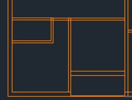
Draw a line connecting right wall edge of bedroom in flat B
Type ‘o’ or offset and press enter or click offset from the modify tool bar
- Specify offset distance: Type 1250 and press enter
- Select object to offset: Select the line drawn earlier and click on left
Type ‘o’ or offset and press enter or click offset from the modify tool bar
- Specify offset distance: Type 125 and press enter
- Select object to offset: Select the last offset line and click on left
Draw line at the top edge of bathroom above
Type ‘o’ or offset and press enter or click offset from the modify tool bar
- Specify offset distance: Type 2150 and press enter
- Select object to offset: Select the line drawn earlier and click on left
Type ‘o’ or offset and press enter or click offset from the modify tool bar
- Specify offset distance: Type 250 and press enter
- Select object to offset: Select the last offset line and click on left
Draw balcony using line command
Trim off extra portions to as the final figure as shown below
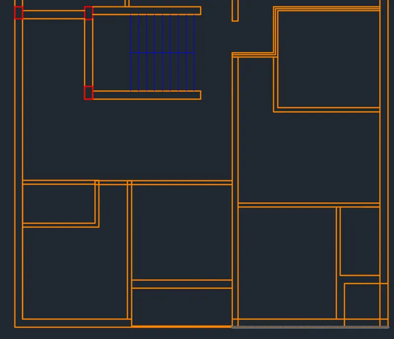
- Create the door openings as per the dimensions from introduction
- Create window openings as per step 4 and dimensions from the introduction
- Assign layers accordingly as per layers cretaed
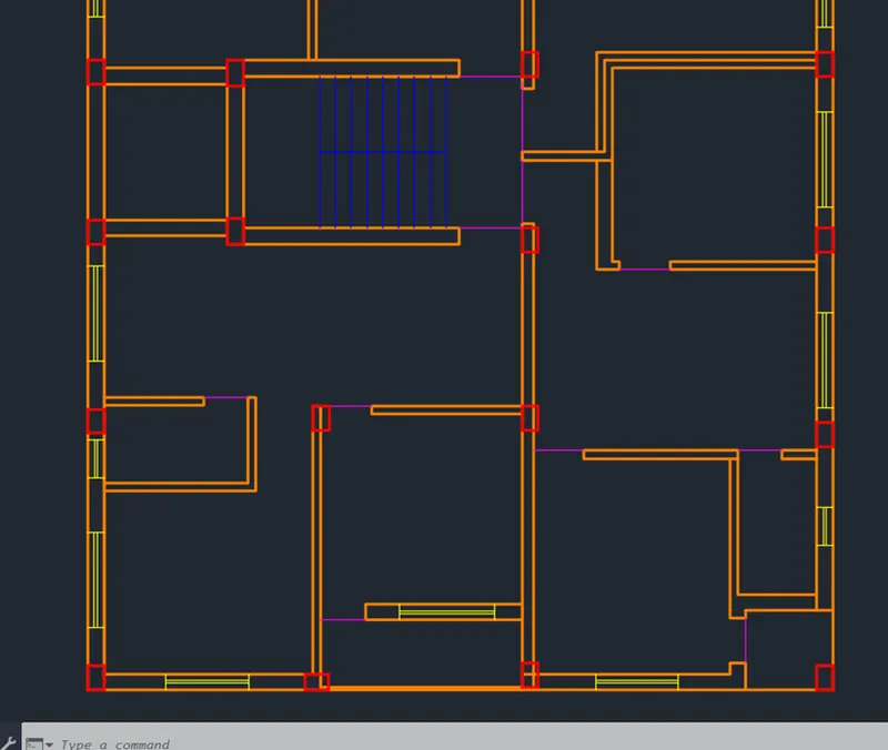
- The final figure after creating walls and columns of flat A and B along with stairs is
Creating Windows and Doors
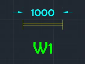
Window
- Using line command draw a line across the wall
- Offset the line through a distance of 1000
- Using line command draw two lines connecting the above drawn lines at the middle
- All windows are created with same procedure and dimensions from the introduction
Door
- Doors are created using line command as shown below
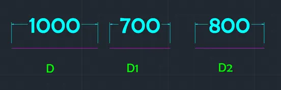
- Doors and windows are copied from creation point and pasted where ever required
- Use DIMBREAK command where ever dimensions are intersecting
- Hatching is done for columns with hatch pattern AR-CONC
- Window shades are created around all windows using ISO dash space - - - - - - - - line type
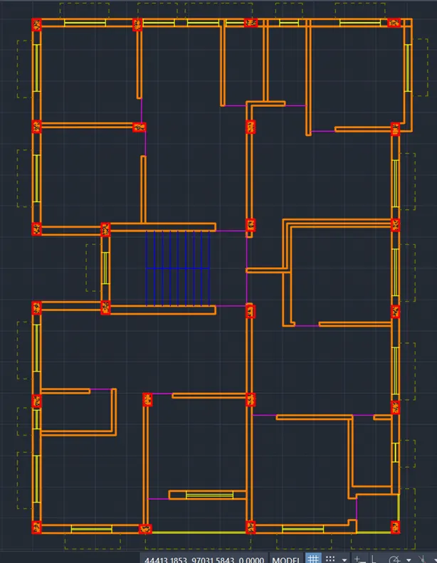
- The final result of step 2, 3 and 4 is as follows
Step 3: Creating 3D View
Change the workspace settings to ‘3D Modelling’
Go to view cube and click on the top view
I. Creating Regions/ Boundaries
For creating boundaries there should not be any open edges, so some changes are made to the walls of the building such as
- Change the layers of column to walls
- Freeze layers of dimension, windows and window shades for better workability
- Trim and delete all the extra portion of the walls and columns to extrude the house as one single wall
Change the current layer to ‘wall’
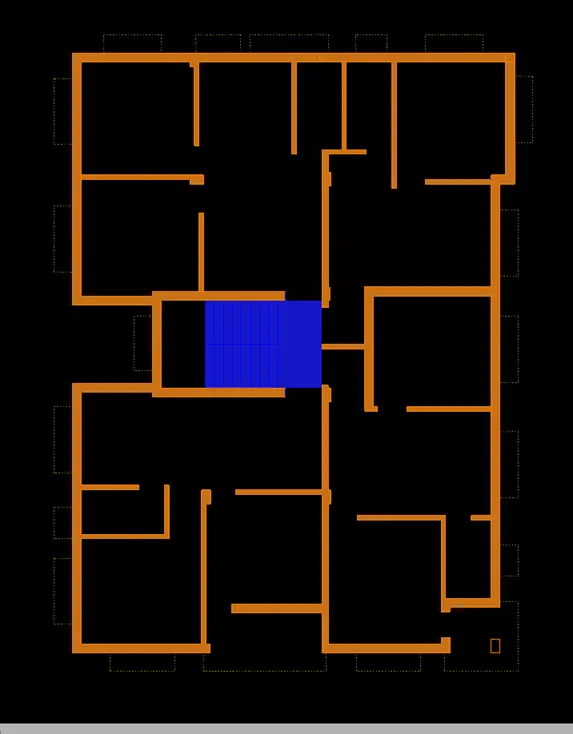
Start boundary command
- Click on pick points
- Select inside all the wall boundaries as shown in figure
Do similar process to stairs as shown in figure
II. Extrusion
Go to view cube and click on the home button
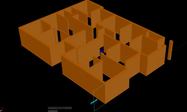
Select all the regions and join them together
Start Extrude command
- Select all the component boundaries created as shown in above figure
- Extrude all the components selected to a distance of 2735mm as shown in figure
Step 4: Creating 3D elements of the residential building
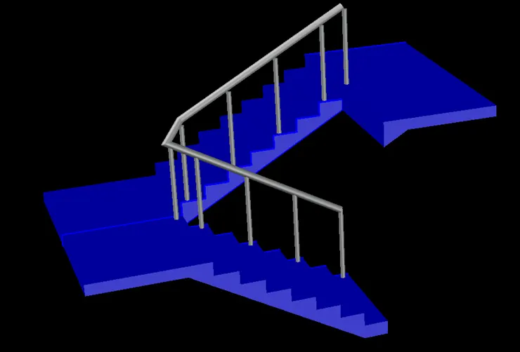
I. Creating Staircase 3D view
Staircase is the common part for the all the four flats and it connects different floors
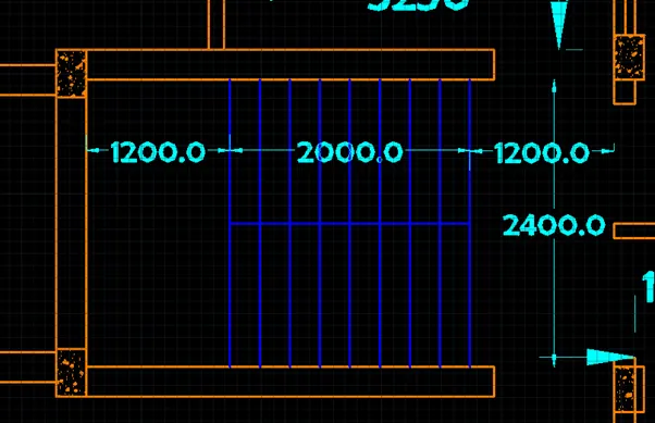
Staircase dimensions and landing thickness are taken from the plan view and introduction as shown in figure
Change the UCS view to front
Change the view from view cube to front view
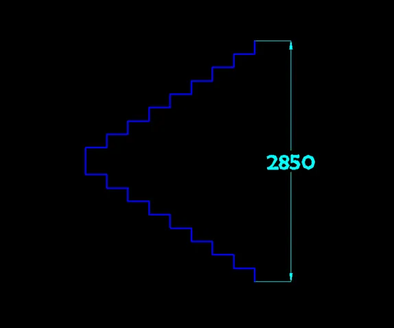
Start line command
- Draw a vertical line of height 158.33mm
- Draw a horizontal line of length 250mm
- Repeat the same process for 8 steps
- Draw another vertical line twice of height 158.33mm
- Change the direction of stairs and follow the same procedure till another 8 steps as shown in figure
- Draw the landing on both sides of length 1200mm and of thickness of slab as 115mm
- Draw line from bottom point of first step horizontal of length 250mm
- Draw a line vertically down of distance 158.33 from the top step of first flight
- Connect the above 2 lines for drawing stair slab for both flights as shown in figure
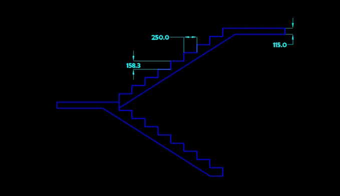
- Draw beams for stair slab as shown in figure
- Create regions of both flights and landings separately
- Extrude first flight in positive direction and second flight in negative direction to a distance of 1200mm
- Extrude the landing for 1400mm as shown in figure
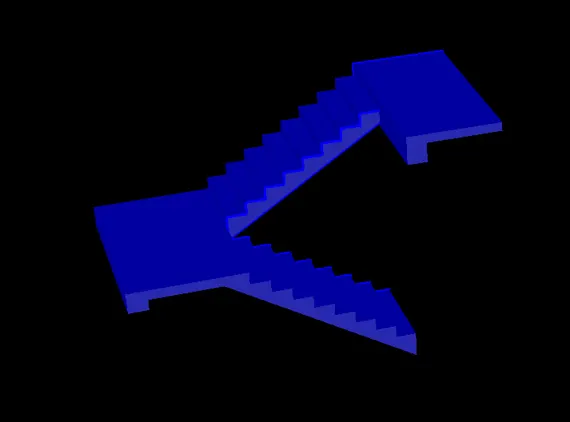
- Draw the vertical part of hand rails on alternate steps as a circle and extrude them to a height of 800mm
- Draw a poly line connecting all the vertical rails
- Draw a circle at the top of one hand rail
- Create a region of the hand rail and sweep it along the length of polyline as shown in figure
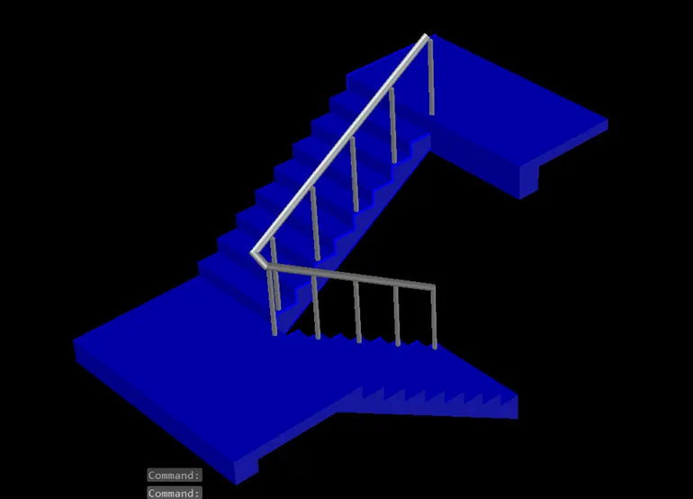
- Similarly ground floor stairs are drawn with raiser height 143.75 as shown in figure
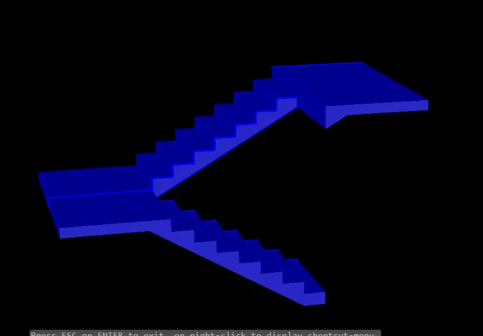
- Create regions and extrude as shown in figure
- Add hand rails similar to stairs created for rest of the floors
II. Creating Doors
There are three door types of different dimensions as per the introduction
i. Door 1:
A model door as shown in figure is drawn with dimensions 1000X2200
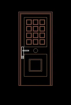
- Change the current layer to respective layer and create the regions where ever required using boundary command
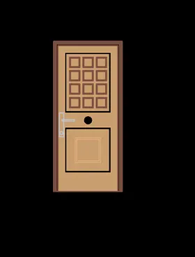
- Create 3D view of Door by extruding the frame and mullion components as shown in figure
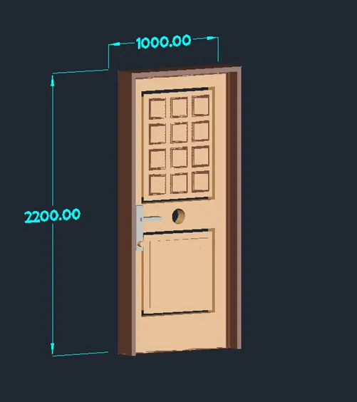
The above model is created into a block
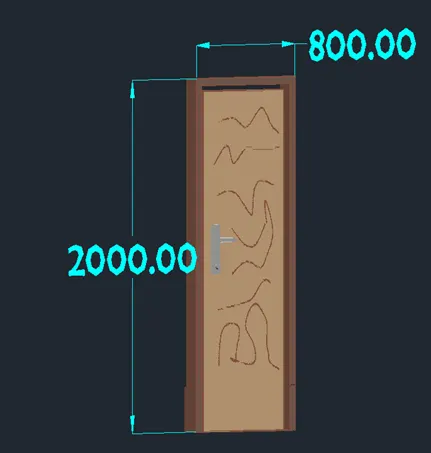
ii. Door 2
A model door as shown in figure is drawn with dimensions 800X2000
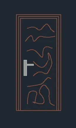
- Change the current layer to respective layer and create the regions where ever required using boundary command
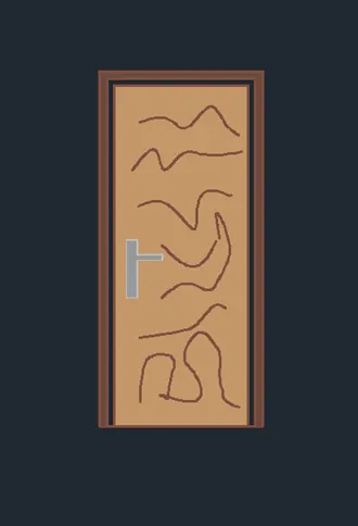
- Create 3D view of Door by extruding the frame and mullion components as shown in figure
iii. Door 3:
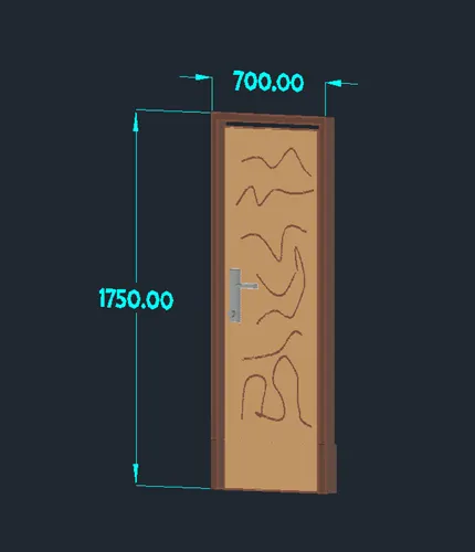
A model door as shown in figure is drawn with dimensions 700X1750
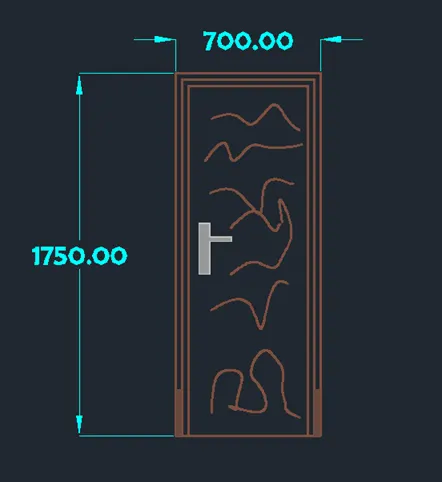
- Change the current layer to respective layer and create the regions where ever required using boundary command
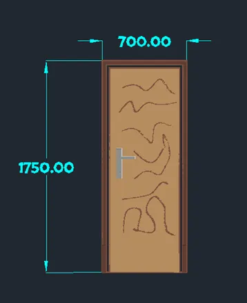
- Create 3D view of Door by extruding the frame and mullion components as shown in figure
Adding Doors to 3D model
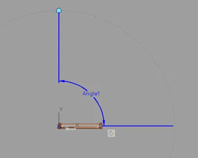
Convert all types of doors into a 3D model blocks
Go to block editor and add rotate parameters and rotate action to all the door types
III. Creating Windows
i. Window 1
Change the current layer to Window Frame
- Draw a window of dimension 1000mmX1200mm
- Offset the rectangle to inside distance of 50mm
- Offset the same to a distance of 30mm to inside
- Offset the same to a distance of 20mm to inside
- Draw a line connecting midpoints of the inner rectangle
- Offset the lien to both side by 10mm
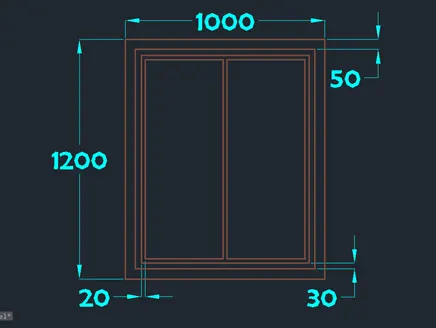
- Create the regions using boundary command
- Subtract the common region using SUBTRACT command
- Change the current layer accordingly.
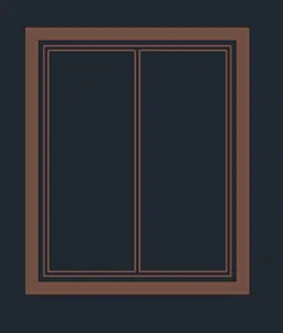
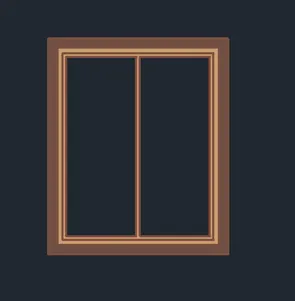
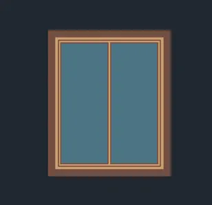
- Extrude the layers by change the current layer to respective layers
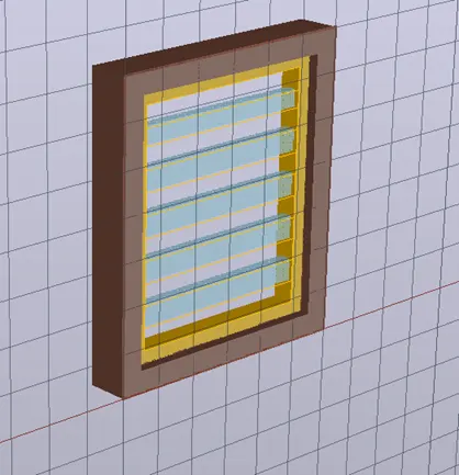
- Move the mullion and glass to inside to create a 3D view as shown in the following figure.
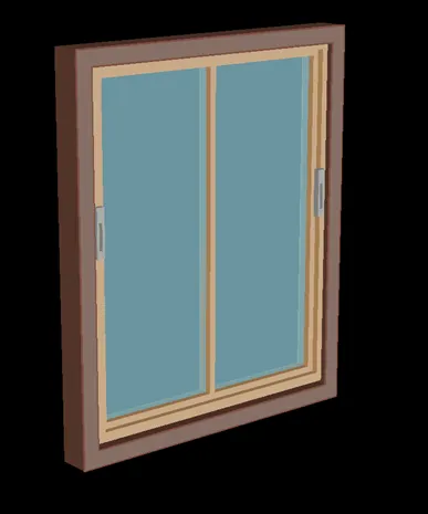
ii. Window 2:
Change the current layer to Window Frame
- Draw a window of dimension 1300mmX1200mm
- Offset the rectangle to inside distance of 50mm
- Offset the same to a distance of 30mm to inside
- Offset the same to a distance of 20mm to inside
- Draw a line connecting midpoints of the inner rectangle
- Offset the lien to both side by 10mm
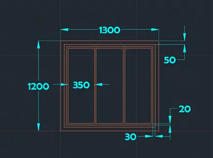
- Create the regions using boundary command
- Subtract the common region using SUBTRACT command
- Change the current layer accordingly.
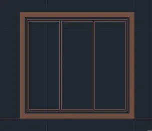
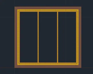
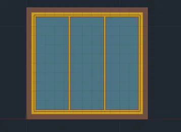
- Extrude the layers by change the current layer to respective layers
- Move the mullion and glass to inside to create a 3D view as shown in the following figure.
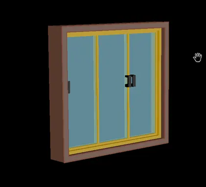
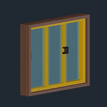
iii. Window 3:
Change the current layer to Window Frame
- Draw a window of dimension 1300mmX1200mm
- Offset the rectangle to inside distance of 50mm
- Offset the same to a distance of 30mm to inside
- Offset the same to a distance of 20mm to inside
- Draw a line connecting midpoints of the inner rectangle
- Offset the lien to both side by 10mm
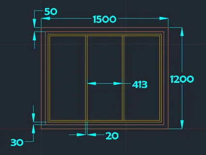
- Create the regions using boundary command
- Subtract the common region using SUBTRACT command
- Change the current layer accordingly.
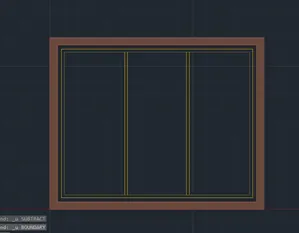
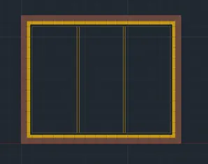
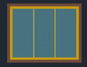
- Extrude the layers by change the current layer to respective layers
- Move the mullion and glass to inside to create a 3D view as shown in the following figure.
iv. Window 4:
Change the current layer to Window Frame
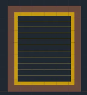
- Draw a window of dimension 600mmX700mm
- Offset the rectangle to inside distance of 50mm
- Offset the same to a distance of 30mm to inside
- Offset the same to a distance of 20mm to inside
- Draw a line connecting midpoints of the inner rectangle
- Offset the lien to both side by 10mm
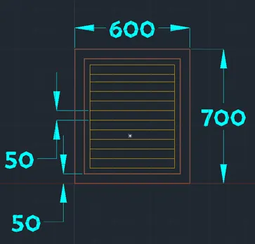
- Create the regions using boundary command
- Subtract the common region using SUBTRACT command
- Change the current layer accordingly.
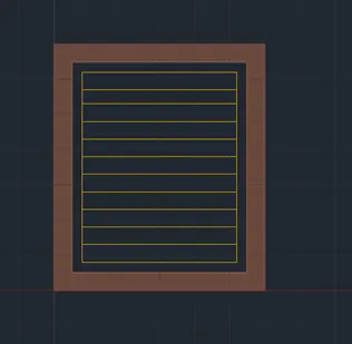
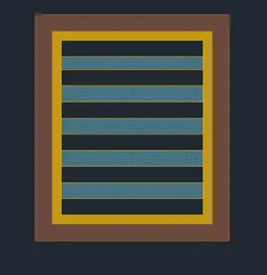
- Extrude the layers by change the current layer to respective layers
- Move the mullion and glass to inside to create a 3D view as shown in the following figure.
IV Window shades
Change the current layer to window shade
Change the UCS to right or left side
- Draw a horizontal line of length 500mm
- Draw a vertical line of length 50mm to the top from last point
- Draw a horizontal reverse line of length 500mm from last point
- Press enter twice
- Draw a vertical line from the start point of length 100mm
- Draw a vertical line of length 50mm to the top from last point
Edit the top horizontal line by grips and draw the one end and place it on the point at 100mm above the bottom point as shown in figure
Create a region of the closed area as shown in figure
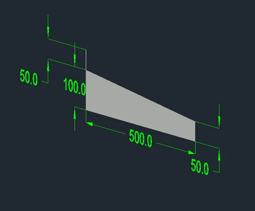
Make many copies of the same
- Extrude the region created depending the required length +200mm i.e 100mm offset on both sides as shown below.
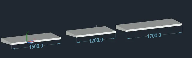
The next step is to create opening for windows in the wall of the building
- Create a rectangle region at the location of the window
- Extrude the rectangle to thickness of wall
- Subtract the rectangle region to create the opening as shown in figure
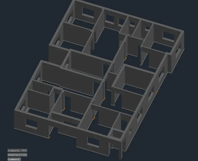
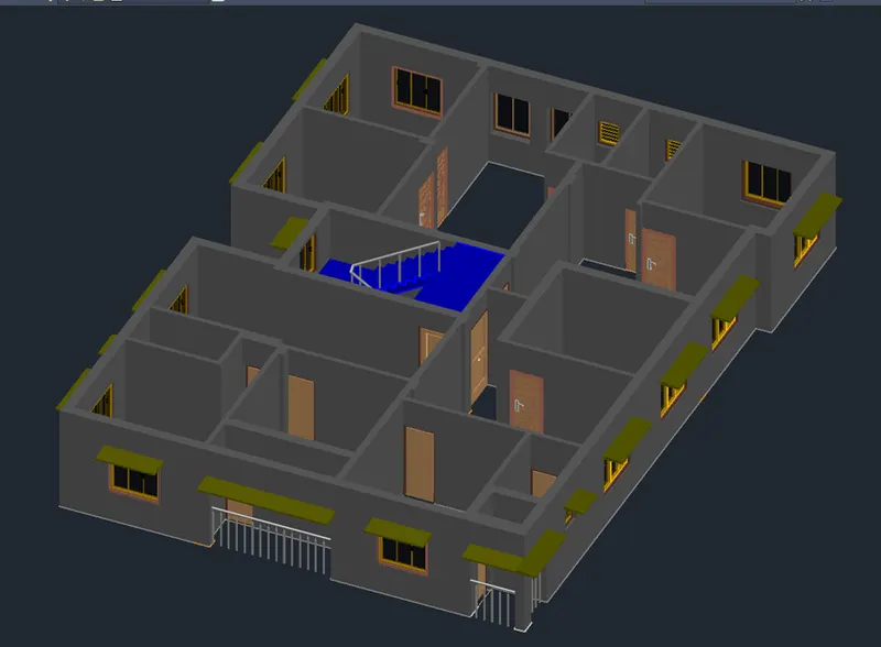
Add respective doors, windows and window shades created at respective locations as shown in the following figure.
Step 5: Creating Superstructure
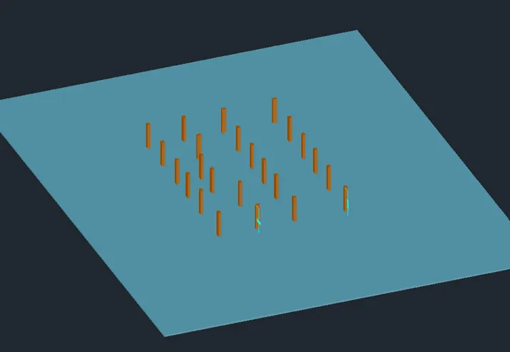
Ground Floor: Ground floor contains floor, columns and connecting stairs
Go to Plan view
- Select one column and right click and click on select similar
- Copy the selection with a base point and paste it at some distance from the plan
Change the current layer to column layer
- Start region command and select all the columns pasted earlier
- Extrude the regions created to height of 2450mm as shown in figure
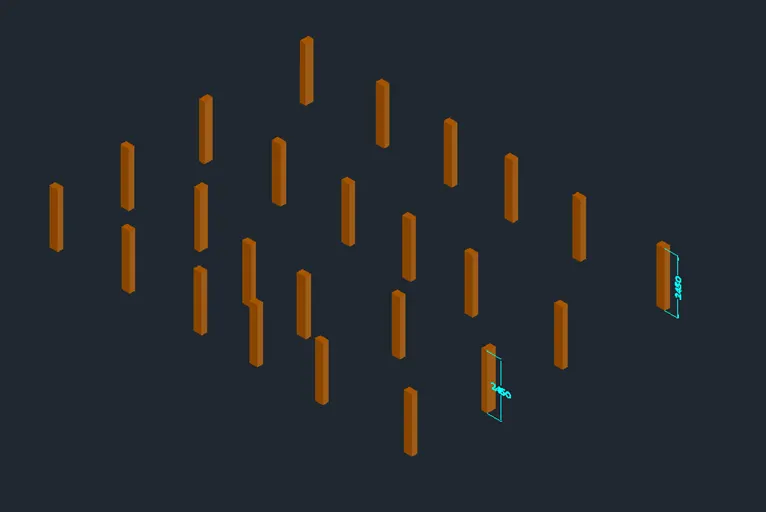
Change the current layer to ground level
- Draw a rectangle of some dimension such that entire building area is covered
- Create the region the rectangle created
- Extrude the rectangle region to a distance of 150mm to above as shown in figure.
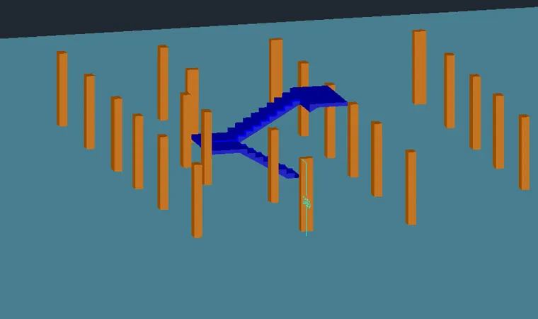
Add staircase created for the ground floor as shown in figure.
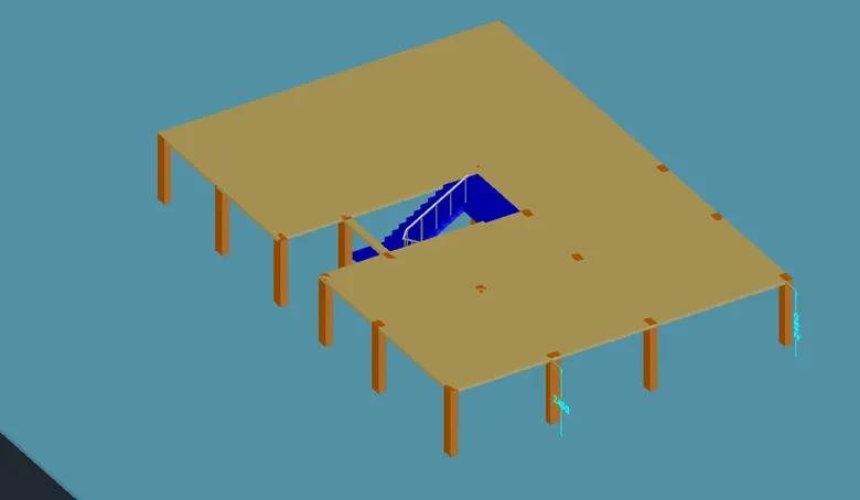
Change the current layer to slab
- Draw a rectangular slab connecting column edge points as shown in figure leaving the staircase open.
- Convert the rectangles drawn in to region
- Extrude the slab down to distance of 115mm as shown figure
Go to first floor 3D drawing
- Draw rectangles that cover the area of the slab
- Convert the rectangles into region
- Group all the rectangles into one
- Select the group and extrude them to a height of 115mm as shown in figure
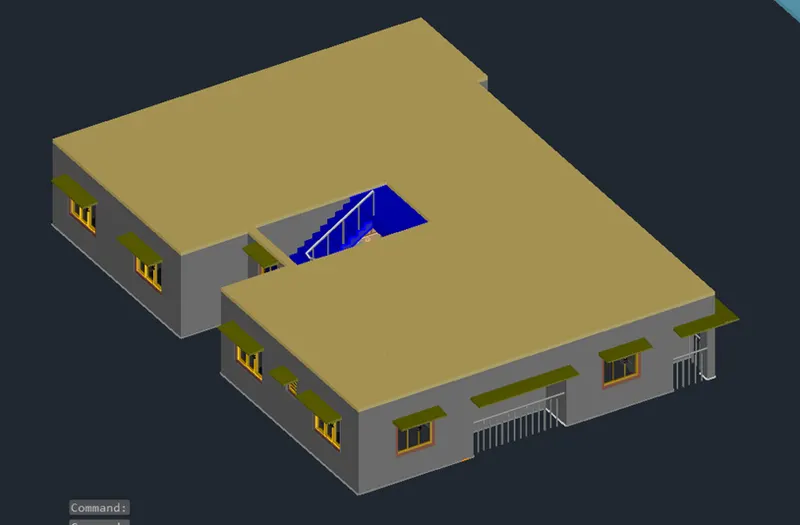
Some elevation features added to windows on all sides except for W4 types
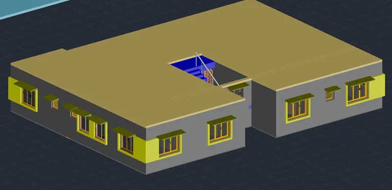
Roof Plan
At the top of the superstructure, it contains parapet wall access to roof door, overhead tank etc.
- They are created with base outer boundary of the roof
- Parapet wall is created by using sweep command
- Door type 2 is set as access to the door.
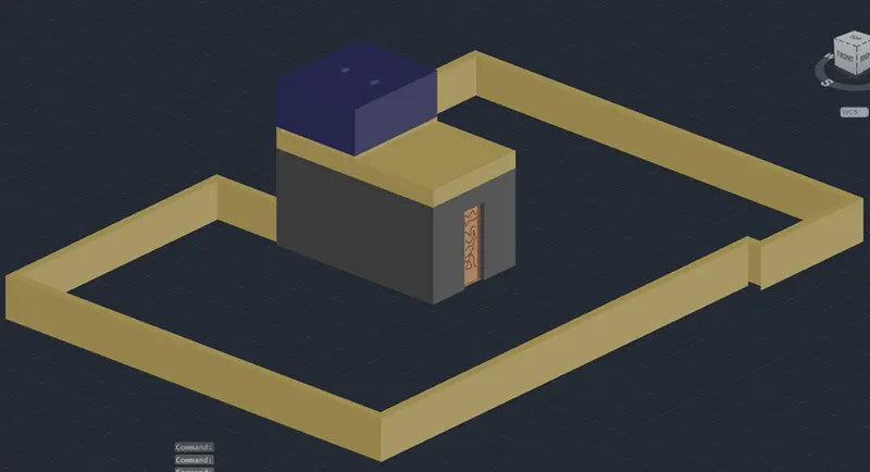
Creating Super structure
Once the ground floor plan and first floor plan are completed, the next step is to create superstructure with four floors
- Copy the entire first floor plan created and paste it on the top of ground floor plan
- Repeat the same process three times to keep 4 floors
- Add the roof top as shown in figure
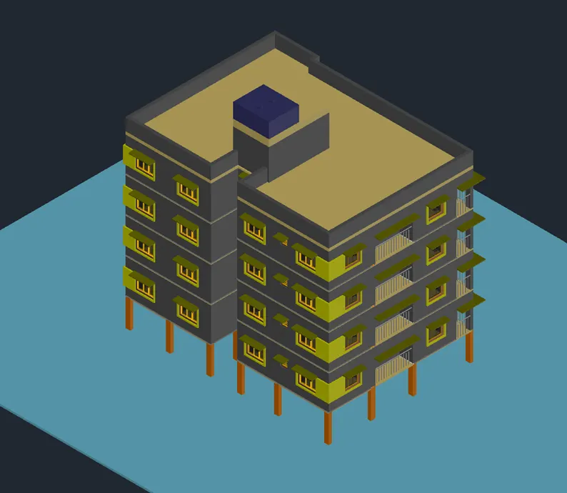
Some other elevation features are added for all the floor balconies on the front side and right side as shown in figure
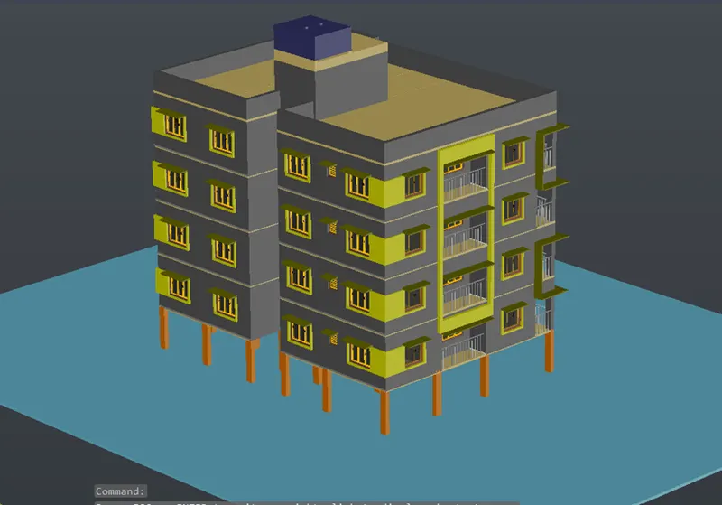
All the elevation features are shown using views created in the next step which are shown in result
Step 6: Creating Views
Click on home button of the view cube and zoom for better view
Go to visuvilise tab and click on new view
- Set view name as VIEW 1 SW Isometric
- Click on current view and press ok
Click on the SE Iso view of the view cube and zoom for better view
Go to visuvilise tab and click on new view
- Set view name as VIEW 2
- Click on current view and press ok
Click on theNE Iso view of the view cube and zoom for better view
Go to visuvilise tab and click on new view
- Set view name as VIEW 3
- Click on current view and press ok
Click on the NW Iso view of the view cube and zoom for better view
Go to visuvilise tab and click on new view
- Set view name as VIEW 4
- Click on current view and press ok
The above created views are shown in result as a part before rendering is done.
Step 7: RENDERING
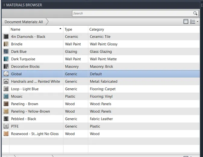
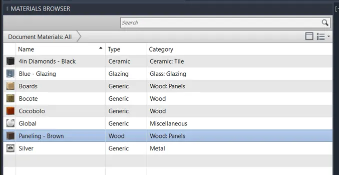
Rendering is done by adding materials to the 3D view
- Material Browser is used for adding materials to objects
- The materials added for the components from the material browser are shown below
Superstructure Rendering
Furniture Rendering
- Box mapping is done to adjust the texture of the wall
Result:
The project aims to draw a rendered view of a residential building. Initially, Layers are created in step 1. Then plan view of the residential building is drawn which is the same for all floors as shown in step 2. After that drafting and annotation settings are changed to 3D Modelling advanced for drawing a 3D view of the plan. From step 3, a 3D view of the residential building floor plan and extrusion of walls is done. In the next step 3D view of components of the building such as the staircase, doors and windows are drawn. In the next steps adding components to the building and created superstructure is done. In step 6 different views are created to show the result of the project. In the final step of the procedure, 3D Rendering process for the residential building and all the assigned materials are shown for both superstructure and also components of the building separately as most of them are not visible in the superstructure.
- All dimensions of all components are in millimeters.
- All Rendering views are shown in the result of both super structure and also components of the building.
- Building component views are shown in step 4.
Plan View
SW Isometric
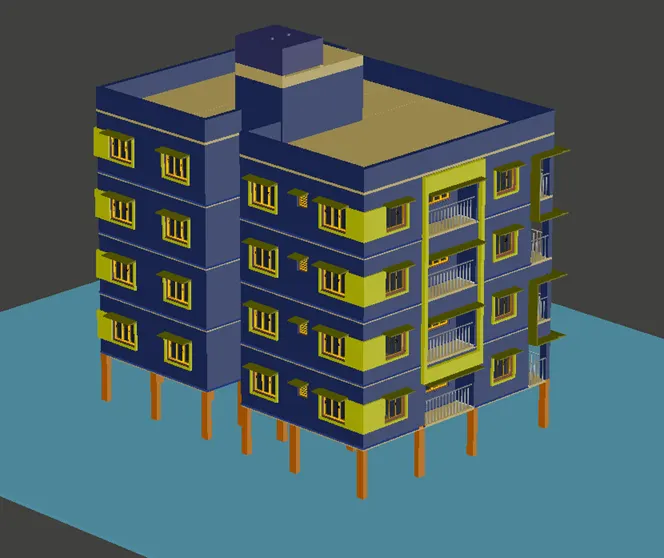
SE Isometric
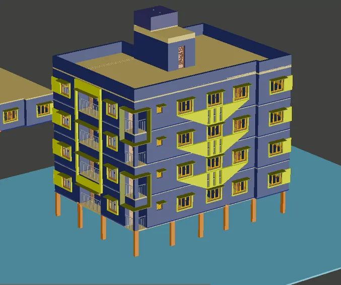
NW Isometric
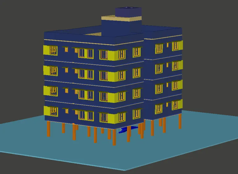
SW Render View
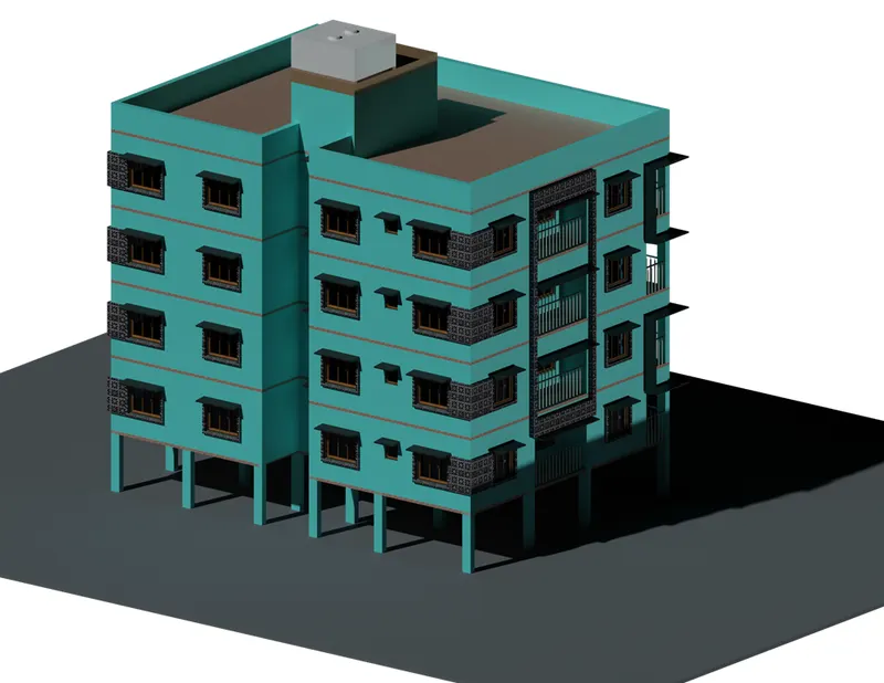
SE Render View
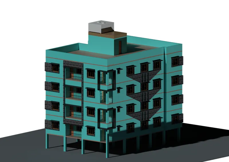
NE Render View
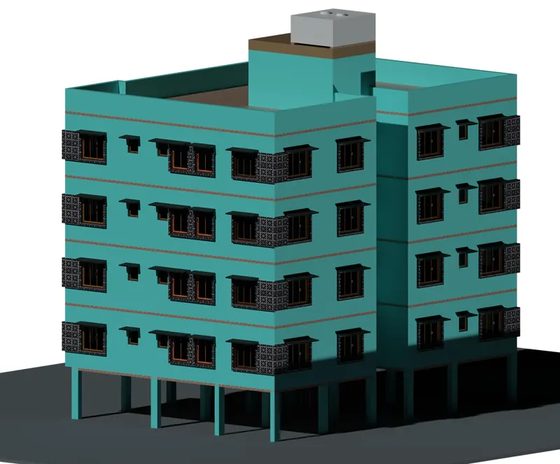
Staircase Render View
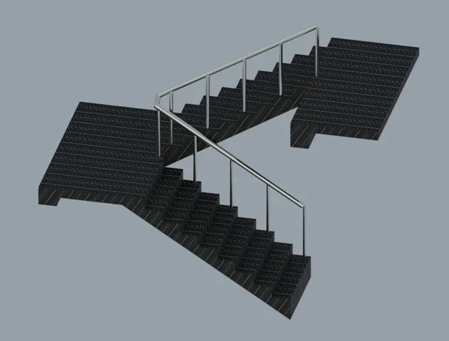
Door 1 Render View
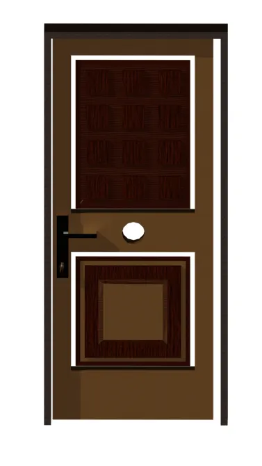
Door 2 Render View
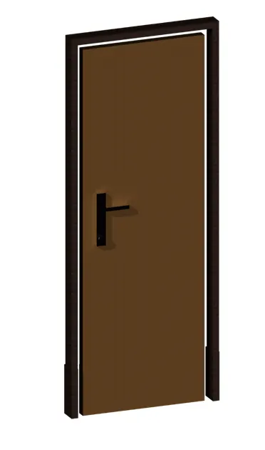
Window 1- Render View
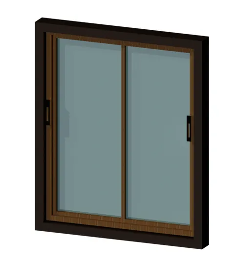
Window 2- Render View
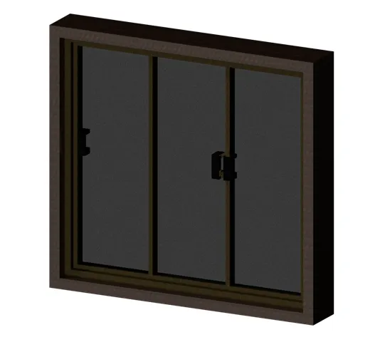
Window 3- Render View
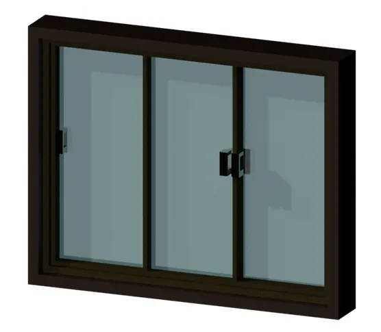
Window 4- Render View
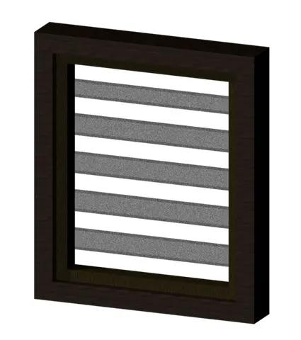
Elevation Feature Rendering