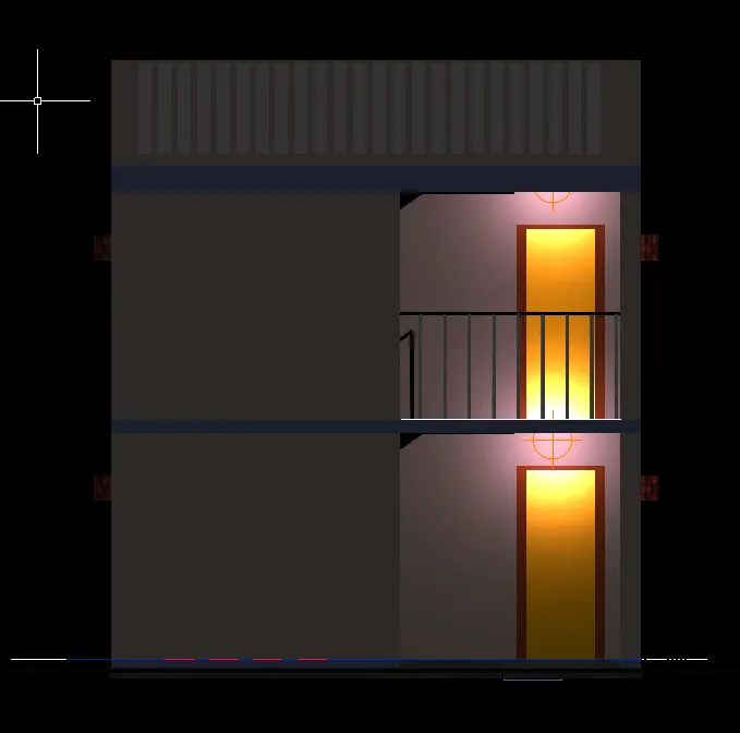
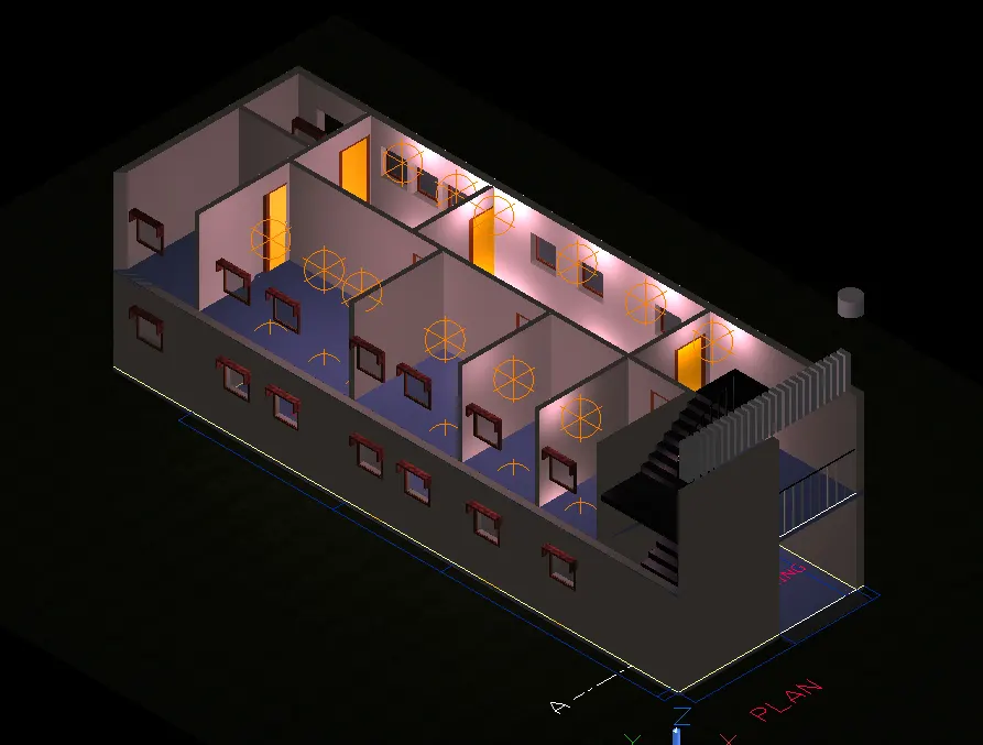
Creating a 3D rendered model for a Residential Building in AutoCad
Aim:
Creating the plan for the residential building of the 60*20 building with the AutoCAD 3D and providing the isometric 3D view with all the materials assigned to the structure and rendered as per required formalities. This process of drawing the model was briefly explained to the better understanding.
Procedure:
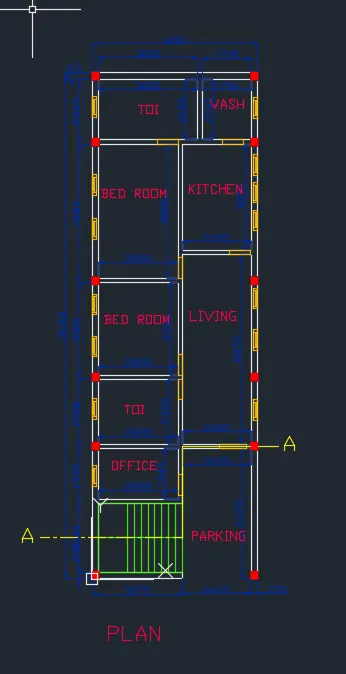
I. In command prompt type (startup:1)
II. Then file>new
III. Then create new drawing window select metric in default settings
IV. In advanced setup in units check on the decimal, angle in degrees, then ok
V. In command prompt type plan and select the current ucs
VI. draw a reference line in the x-direction and the y-direction of the 20000
VII. Next, in command prompt type (o and specify distance of offset as 3000) and offset the horizontal line to top
VIII. Next, in command prompt type (o and specify distance of offset as 1800) and offset the horizontal line to top
IX. Next, in command prompt type (o and specify distance of offset as 2500) and offset the horizontal line to top
X. Next, in command prompt type (o and specify distance of offset as 3500) and offset the horizontal line to top
XI. Next, in command prompt type (o and specify distance of offset as 5000) and offset the horizontal line to top
XII. Next, in command prompt type (o and specify distance of offset as 3000) and offset the horizontal line to top
XIII. Next, in command prompt type (o and specify distance of offset as 2500) and offset the horizontal line to top
XIV. Next, in command prompt type (o and specify distance of offset as 4800) and offset the horizontal line to top of bottom line
XV. Next, in command prompt type (o and specify distance of offset as 7000) and offset the horizontal line to top
XVI. Next, in command prompt type (o and specify distance of offset as 4000) and offset the horizontal line to top
XVII. Next, in command prompt type (o and specify distance of offset as 2200) and offset the vertical line to right
XVIII. Next, in command prompt type (o and specify distance of offset as 1000) and offset the vertical line to right
XIX. Next, in command prompt type (o and specify distance of offset as 2800) and offset the vertical line to right
XX. Next, in command prompt type (o and specify distance of offset as 2400) and offset the vertical line to right
XXI. Next, in command prompt type (o and specify distance of offset as 2300) and offset the vertical line to right
XXII. Offset all exterior lines to 230 inwards and offset all interior line for 75 on both sides and delete the original line
XXIII. Now, trim and fillet all the required lines
XXIV. Create a block of the square of 250*250 as column and co this blocks to the required positions
XXV. Now using rectangle command draw the rectangle boundary for the staircase and explode the rectangle and oddest it by 250mm.
XXVI. Create a block of the rectangle as window and doors and co this blocks to the required positions
XXVII. Select all create a layer of walls in orange colour
XXVIII. SELECT THE GREEN LAYER FOR STAIRCASE
XXIX. draw one raiser and footer and ten copy to the top floor
XXX. and draw the parallel line to the steps with snapping
XXXI. form the parallel lines draw the railings of the stairs
XXXII. In command prompt type (xl enter h enter v) construction line horizontal and vertical respectively is obtained
XXXIII. Next, in command prompt type (o and specify distance of offset as 2720) and offset the horizontal line to top
XXXIV. Next, in command prompt type (o and specify distance of offset as 2895) and offset the vertical line to right
XXXV. Next, in command prompt type (o and specify distance of offset as 150) and offset the vertical line to right
XXXVI. Next, in command prompt type (o and specify distance of offset as 2725) and offset the vertical line to right
XXXVII. Enter
XXXVIII. Now type bo in the command prompt and wake the boundary command
XXXIX. Pick a point as the space between the wall therefore the wall portion is created as the region
XL. If this doesn’t work then in command prompt type 3d which wakes the 3dface command
XLI. And then create the required face over the wall sections
XLII. Then type reg to wake region command and make the created 3dfaces as the region
XLIII. Now type EXT in the command prompt and wake the extrude command
XLIV. Select all the regions over the wall section and in the z direction extrude it for the height of the 2720
XLV. Go to the custom view and check the model once
XLVI. In command prompt type UNI and wake the union command and select the all objects and combine them
XLVII. Enter
XLVIII. Select all the walls extruded and and change the properties to the wall layer
XLIX. Enter
L. Away from the model draw the section and elevation view for the reference
LI. Section AA
LII.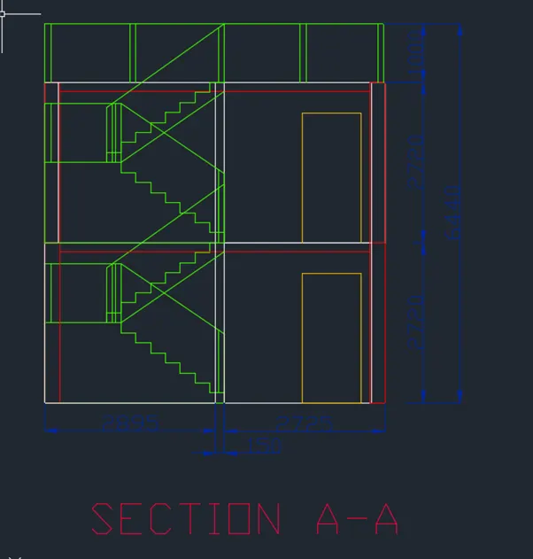
LIII. SELECT THE GREEN LAYER FOR STAIRCASE
LIV. draw one raiser and footer and ten copy to the top floor
LV. and draw the parallel line to the steps with snapping
LVI. form the parallel lines draw the railings of the stairs
LVII. In command prompt type (xl enter h enter v) construction line horizontal and vertical respectively is obtained
LVIII. Next, in command prompt type (o and specify distance of offset as 2720) and offset the horizontal line to top
LIX. Next, in command prompt type (o and specify distance of offset as 2895) and offset the vertical line to right
LX. Next, in command prompt type (o and specify distance of offset as 150) and offset the vertical line to right
LXI. Next, in command prompt type (o and specify distance of offset as 2725) and offset the vertical line to right
LXII. Draw a rectangle with the column layer of 250*2750 at both the corner and offset 150 of the top line and set to current layer as beam
LXIII. And copy the entire objects as the 2nd floor
LXIV. Draw a 1000mm vertical line at top floor and offset to the required positions and draw the horizontal line connecting last lines.
LXV. Select all the section elements and the type the group in the command prompt and group the whole section
LXVI. Now type the 3dr in command prompt to wake the 3drotate in the 3d
LXVII. Select the group as the object and specify the base point as the bottom corner and pick the y axis as the axis of rotation and specify the angle as the 90
LXVIII. And ungroup the whole section
LXIX. Select the door section create the region of the exterior wall line then copy it to the any specified point make its layer as the dumi door
LXX. Switch off the wall layer
LXXI. Select the dumi wall and copy it
LXXII. And the place it in the all portion of the door
LXXIII. Enter
LXXIV. Now type layon
LXXV. Next type sub in command prompt to wake the subtract command
LXXVI. Select the wall the first object and then next select all the dumi doors that has to be deleted from the wall section and substract
LXXVII. Then we obtain the pitcher below
LXXVIII.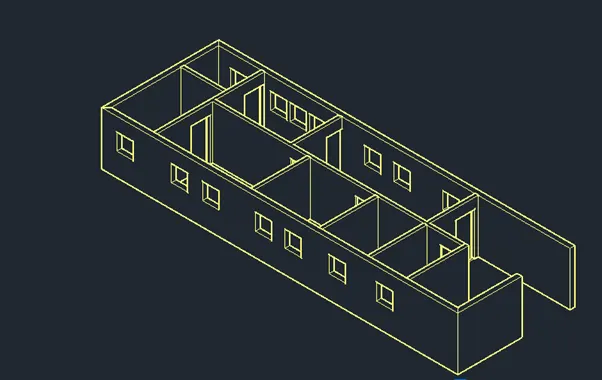
LXXIX. Next go to the door section and create the 2 regions of the frame of the door frame and the door
LXXX. Using the subtract tool form the 2 regions
LXXXI. And extrude the door frame to 200mm
LXXXII. And then extrude the door to 150mm
LXXXIII. And move the door for 25 @0,0,25 along the door frame
LXXXIV. Craeate the 2 layers of the door and door frame and aggign the them respectively
LXXXV. Copy the both door and door frame at once
LXXXVI. And then place in all the wall openings that was created for the door by the bottom corner as the base point
LXXXVII. Similarly
LXXXVIII. In command prompt type (xl enter h enter v) construction line horizontal and vertical respectively is obtained
LXXXIX. Next, in command prompt type (o and specify distance of offset as 4800) and offset the vertical line to right of bottom line
XC. Next, in command prompt type (o and specify distance of offset as 7000) and offset the vertical line to right
XCI. Next, in command prompt type (o and specify distance of offset as 4000) and offset the vertical line to right
XCII. Draw a rectangle with the column layer of 250*2750 at both the corner and offset to all required positions and offset 150 of the top line and set to current layer as beam
XCIII. Using rect command draw window and copy to all respective positions
XCIV. Select all the section elements and the type the group in the command prompt and group the whole section
XCV. Now type the 3dr in command prompt to wake the 3drotate in the 3d
XCVI. Select the group as the object and specify the base point as the bottom corner and pick the y axis as the axis of rotation and specify the angle as the 90
XCVII. And ungroup the whole section
XCVIII. Select the window section from elevation view create the region of the exterior window line then copy it to the any specified point make its layer as the dumi window
XCIX. Switch off the wall layer
C. Select the dumi wall and copy it
CI. And the place it in the all portion of the window
CII. Select all the dumi windows and move it to the @0,0,1250
CIII. Enter
CIV. Now type layon
CV. Next type sub in command prompt to wake the subtract command
CVI. Select the wall the first object and then next select all the dumi windows that has to be deleted from the wall section and substract
CVII. Next go to the window section and create the 3 regions of the frame of the door frame and the door
CVIII. Using the subtract tool form the 3 regions
CIX. And extrude the window frame to 200mm
CX. And extrude the window margin to 100 mm
CXI. And then extrude the window to 50mm
CXII. And move the window margin for 25 @0,0,25 along the window frame
CXIII. And move the window for 25 @0,0,25 along the window margin frame
CXIV. Create the 3 layers of the window margin, window and window frame and assign the them respectively
CXV. Copy all the parts of the window
CXVI. And then place in all the window openings that was created for the door by the bottom corner as the base point
CXVII. Enter
CXVIII.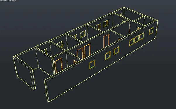
CXIX. Go to the section view and copy the stair boundary and
CXX. Place them in the required position
CXXI. Then select the bo and create the region of the stair and
CXXII. then extrude it to the y direction to 1250
CXXIII. Similarly, do it for the upper landing
CXXIV. So, the doglegged stair is created
CXXV. Change the layer to the stair
CXXVI. Using the circle command create the circle over the first step
CXXVII. Create this circle as the region
CXXVIII. Type EXT in command prompt and wake up the extrude command
CXXIX. Select the circle regions that has to be extruded
CXXX. And move the cursor in the z direction and specify the extrude distance as the 3’
CXXXI. Enter
CXXXII. Now copy the rail and specify the base point as the stairs corner
CXXXIII. And copy it to every stair
CXXXIV. At the landing copy it at the midpoint and end point
CXXXV. At the end of the polyline draw the circle in the xz plane of the 20 dia
CXXXVI. Select the sweep command
CXXXVII. Select the rectangle as the object
CXXXVIII. And polyline connected to the rails as the path for the sweep
CXXXIX. Enter
CXL. Now sweep is created
CXLI. Now, type CO in command prompt and to copy
CXLII. Now select all the rails and the sweep
CXLIII. Specify the base point as the bottom connection to stair and copy to the other side of the stair
CXLIV. Enter
CXLV. Select all and create railings layer
CXLVI. Enter
CXLVII.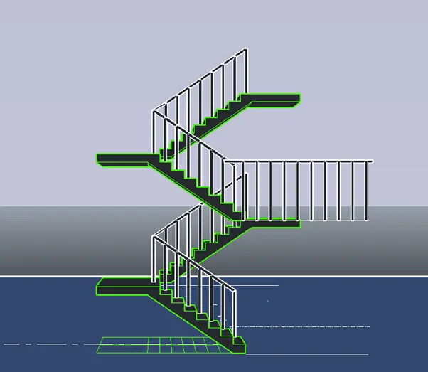
CXLVIII. Select this and move to the required position
CXLIX. Go to the isometric view
CL. Draw the rectangle connect the top corners and make it as the region
CLI. Then extrude the rectangle by 150 on z direction and create the slab
CLII. Slab opening for the staircase
CLIII. Copy this slab to the bottom
CLIV. Draw the rectangle or space required for opening at top
CLV. Create the region by bo command
CLVI. And extrude it by 15 in -ve z direction
CLVII. With the help of the subtract command from the top slab subtract the stair case opening
CLVIII.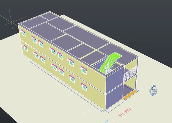
CLIX. Create the rectangle and offset it by 230
CLX. Create the 2 region over the top and sub tract the outer region so that the exterior wll region for roof is obtained
CLXI. And then extrude the region by the 1200 in z direction
CLXII. At the front view create the rectangle
CLXIII. Make it region
CLXIV. And extrude it to the 300 at y direction
CLXV. And select it and type array in command prompt
CLXVI. And specify 24 columns and 1 row between 220
CLXVII. Name the layer as the wood
CLXVIII. Next, go to the visualize tool bar and open material browser
CLXIX. By searching load the all required materials and then
CLXX. With Qselect option select the layer = wall and assign material= wall paint matte
CLXXI. With Qselect option select the layer = stair and assign material= metal fabricated
CLXXII. With Qselect option select the layer = railings and assign material= metal fabricated
CLXXIII. With Qselect option select the layer = door and window margin assign material= red oak
CLXXIV. With Qselect option select the layer = door and window frame and assign material= hard wood
CLXXV. With Qselect option select the layer = slap and assign material= ceramic tile
CLXXVI. With Qselect option select the layer = window and assign material= glass
CLXXVII. With Qselect option select the layer = footing and assign material= concrete
CLXXVIII. With Qselect option select the layer = bottom and assign material= grass
CLXXIX. There fore model will be like
CLXXX.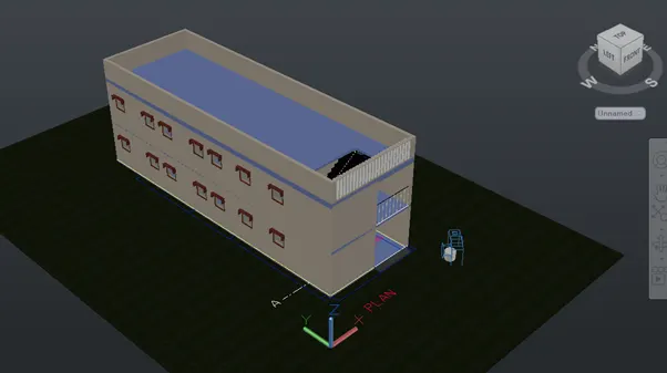
CLXXXI. Place the cylinder of the height 2600 whgere ever the light is required
CLXXXII. In the visuilze tool select the light
CLXXXIII. And place the over the cylinder
CLXXXIV. And select the cylinder and delete them
CLXXXV. Noe select all the lights and the copy them to the respective floor with propper distance
CLXXXVI. Position of the camera
CLXXXVII. First select position where the camera has to be placed and then
CLXXXVIII. Type cyl in command prompt and wake the cylinder command
CLXXXIX. And draw the cylinder at that position
CXC.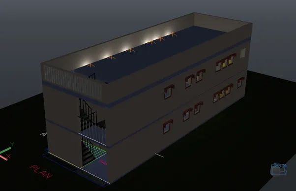
CXCI. Then type cam in the command prompt to wake the camera command
CXCII. And place it on the cylinder and specify the path of the focus
CXCIII. Name the view
CXCIV. Then type v view and y yes
CXCV. Therefore, the camera view is formed
CXCVI. Go to visualize toolbar and in the render select medium
CXCVII. And render window dimension
CXCVIII. And select the view that has to be rendered on screen
CXCIX. Type rr in the command prompt and wake the render command
CC. Therefore, we obtain the rendered model in the render window.
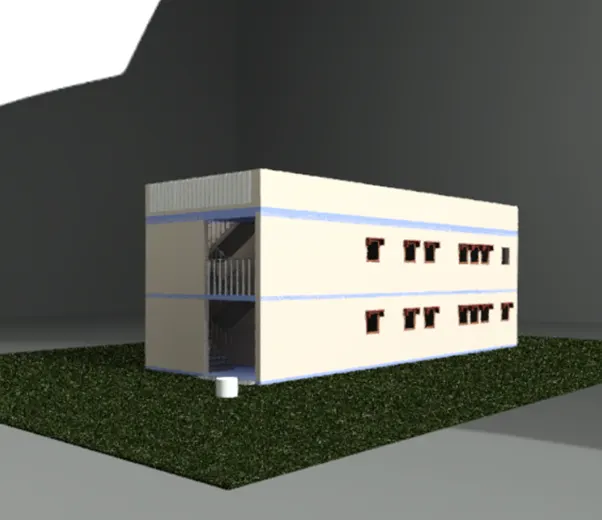
Result:
In this project For the given condition at first the hand sketch draft file was done for the 60*20 site as depending on that the AutoCAD file was created depleting the draft drawing was drawn as shown in the figure 1 and by this plan consideration a section view and the side elevation was visualised and drawn in the AutoCAD as figure 2 and figure3 respectively and layers columns and beams was used during the drawing which will be helpful in differentiating the architectural and structural drawing which shows the position of the columns and beams by this reference a 3d model was created in the Autocad3d software With the proper us of the materials, layers and many other tools to assign the properties and usage of the solid editing was done wherever required and tools like extrude, sweep fillet were very helpful During the drafting of this model
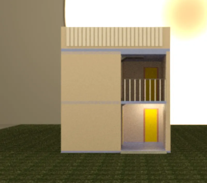
and here are the some of the rendred images of the model
\
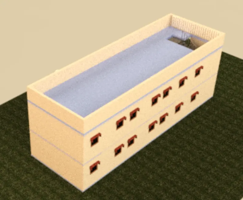
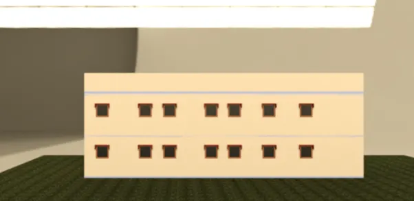
wire frame model
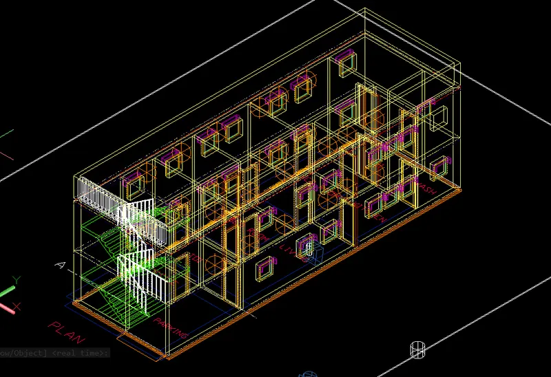
reilestic