Creating 3D Isometric view of various structural elements in AutoCAD
QUESTION 1
AIM
To create a 3D Isometric View of the building with plan and elevation given
PROCEDURE
- Open AutoCAD and set maximum and minimum limit
- Draw a rectangle
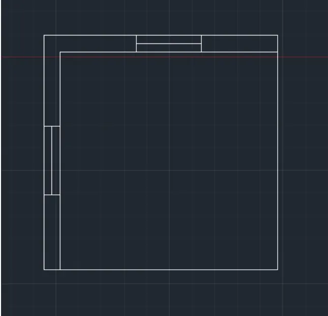
- Draw the two windows of size 3'*9" and 9"*3'2"
- Draw elevation A and B as shown in figure
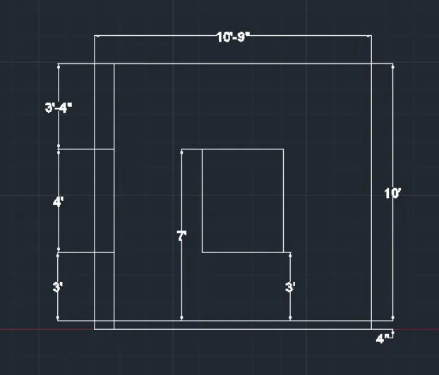
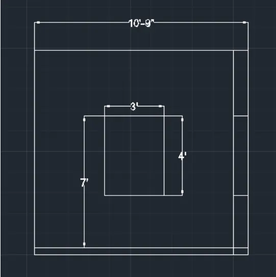
- Draw window of 3' * 4' and extrude it
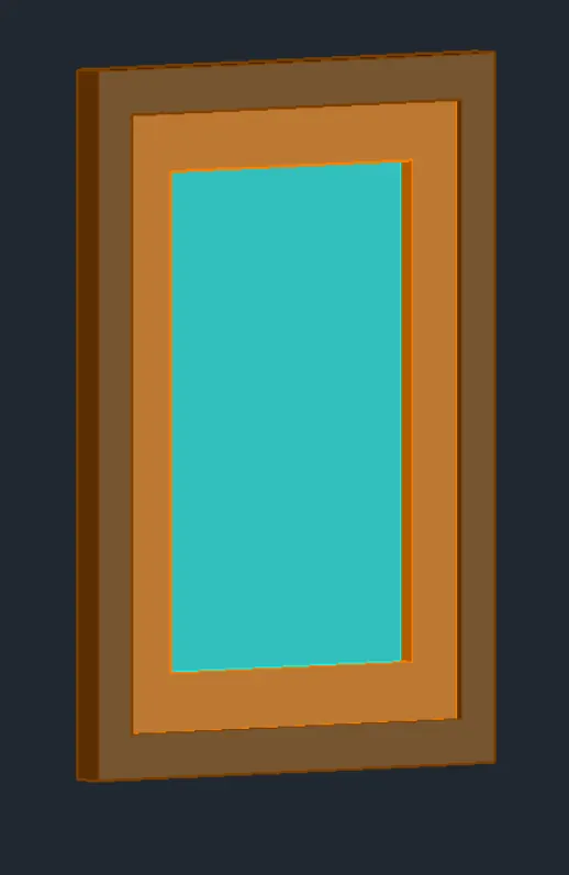
- Draw window of 3'2" * 4' and extrude it
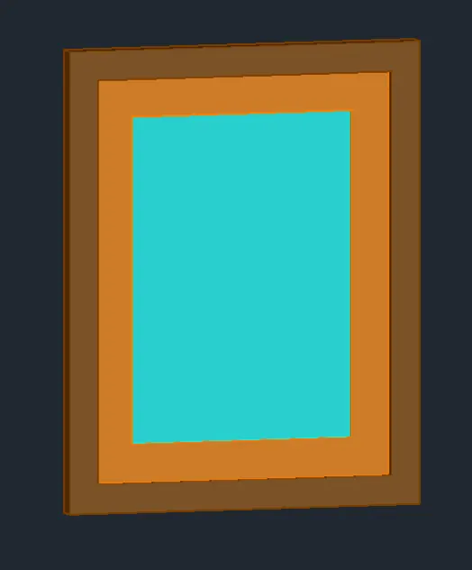
- Draw wall using extrude command
- Use layers for colors to them
- Attach the created windows to the wall
- Use 3D orbit to show a different view
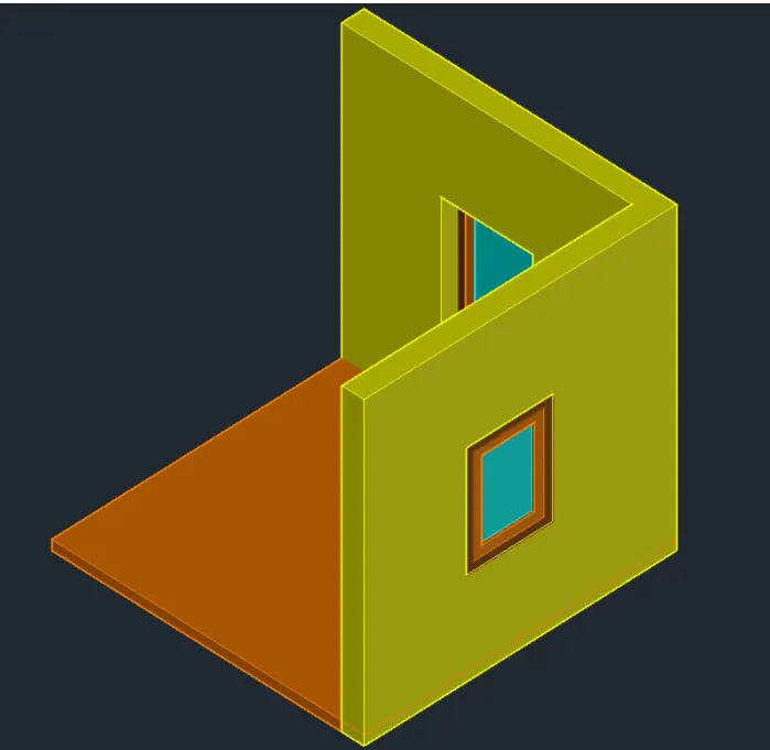
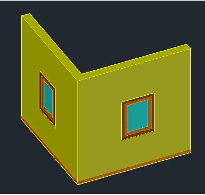
RESULT
The given 3D Isometric View of the building with plan and elevation is created
QUESTION 2
AIM
To create the 3D View of the Building Façade as given in the plan and elevation
PROCEDURE
- Open AutoCAD and set limits and units
- Draw a rectangle and then the window of size 3'2" * 9"
- Use region command and select the object, then press enter
- Then after a total object will become the one region
- Now extrude the plan with the height of 40'10"
- Next, subtract the four window portion vertical in the building faced with the distance 5'11" with a window size of 3'*4'
- Next use the union command and press enter
- Then select total drawing and press enter
- Make window position clear in building as a facade
- Next shade the edges
- Provide the layer for the building faced of sky blue color
- Use extrude command and extend
- Use 3D orbit command to view the front elevation
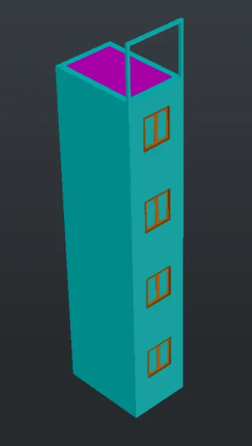
RESULT
The given 3D Isometric View of the building with plan and elevation is created
QUESTION 3
Aim
To create the 3D View of the stair with a railing as shown in the plan and elevation
PROCEDURE
- Open AutoCAD and set limits and units
- Draw stair of 6" of rising and 1' thread
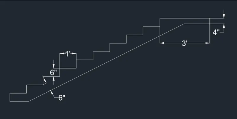
- Use 3D rotate to rotate the diagram
- Now extrude the diagram
- Draw railing using circle command and sweep command
- 3D rotate and show the stairs inside view
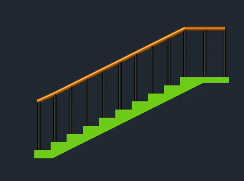
- Now put stairs in 3D isometric view using 3D orbit command
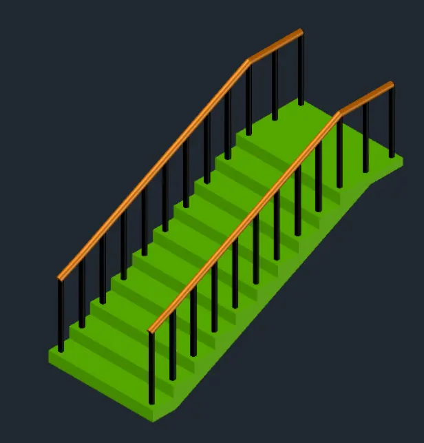
RESULT
The given 3D View of the stair with a railing as shown in the plan and elevation
QUESTION 4
AIM
To create the 3D view of a Wall with spread footing with various aspects
PROCEDURE
- Open AutoCAD and set unit and limit
- Draw a plan of the wall with spread footing with a given dimension
- Draw the isometric view of the wall of spread footing and extrude
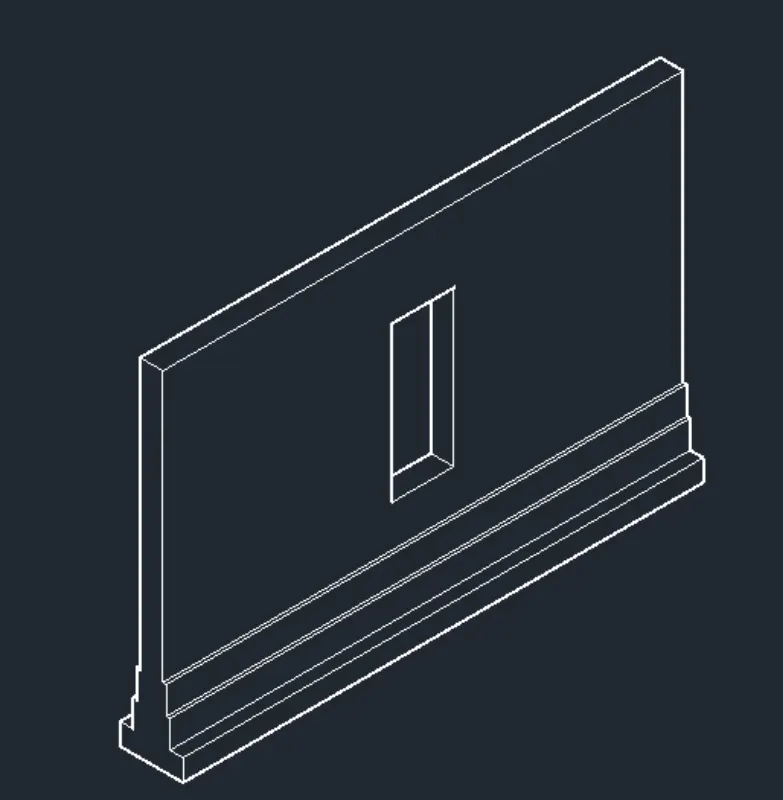
- Provide layers for wall with spread footing with different parts
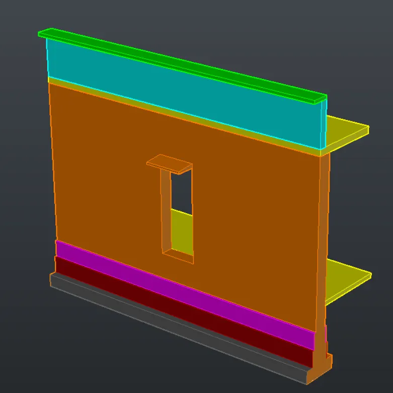
- Provide materials for wall with spread footing with different parts
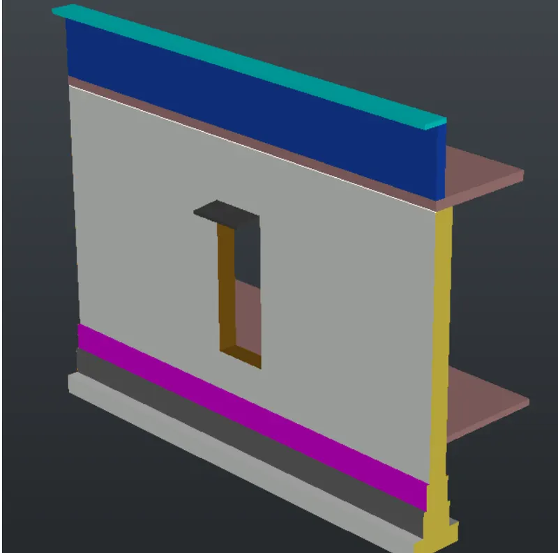
- Select the camera and put in the required position and then press enter
- Click camera the small tab appears as shown
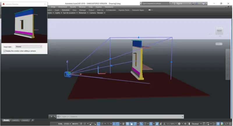
- Select render option and then slowly changes to rendering view
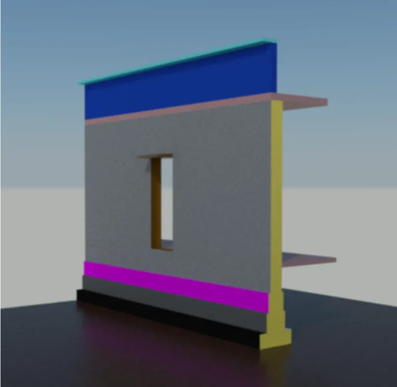
RESULT
The 3D view of a Wall with spread footing with various aspects is created