Creating 3D Isometric view of various structural elements in AutoCAD
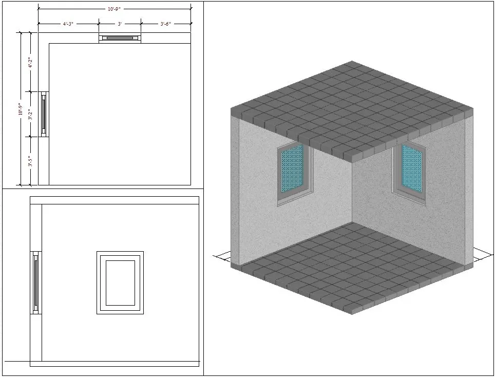
1. Create a 3D Isometric View of the building with plan and elevation given.
Aim : To create a 3D isometric view of the given building with plan and elevation.
Introduction :
- An isometric drawing is a 3D representation of an object, room, building or design on a 2D surface.
- One of the defining characteristics of an isometric drawing, compared to other types of 3D representation, is that the final image is not distorted.
- This is due to the fact that the foreshortening of the axes is equal.
- In an isometric drawing, the object appears as if it is being viewed from above from one corner, with the axes being set out from this corner point.
- Isometric drawings begin with one vertical line along which two points are defined.
- Any lines set out from these points should be constructed at an angle of 30 degrees.
Commands used :
- Line command
- Rectangle command
- UCS command
- Dimlinear command
- Region command
- Extrude command
- Substract command
- Box command
- Units command
- Dimstyle command
- 3D face command
- 3Dorbit command
- Hide command
- Explode command
- Move command
- copy command
- Dist command
- Solid edit command
- Union command
- Boundary command
- 3D mirror command
- 3D rotate command
- Erase command
- Plan command
Procedure :
Step 1 :
- First we have to open the autocad and the set the maximum limits and minimum limit and minimum limits on the screen
- Here first have to draw the rectangle using the rectangle command as shown
- Next we have to draw the two windows of sizes of 3'x9" and 9"x3'-2"
Step 2 :
- Now we draw the elevation of A and the elevation of B, as shown
- We draw the given elevation using the line command and we put the dimensions using the dimlinear command
Step 3 :
- First we draw the windows of the sizw 3'x 4' as shown
- We draw the window using the line command and extruded using the extrude command
Step 4 :
- Next we draw the windowa of the size 3'-2"x4' as shown
- We draw the window using the line command and extrude using the extrude command
Step 5 :
- Next we draw the walls using the extrude command as shown
- Next we use the layers for providing the colours to them
- Next we attach the created windows to the walls as shown
Step 6 :
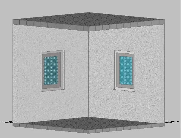
- Next we use the 3D orbit command to see the different views of the given figure
Result :
- The given 3D isometric view of the building with plan and elevation is drawn sucessfully in the autocad in detailed manner
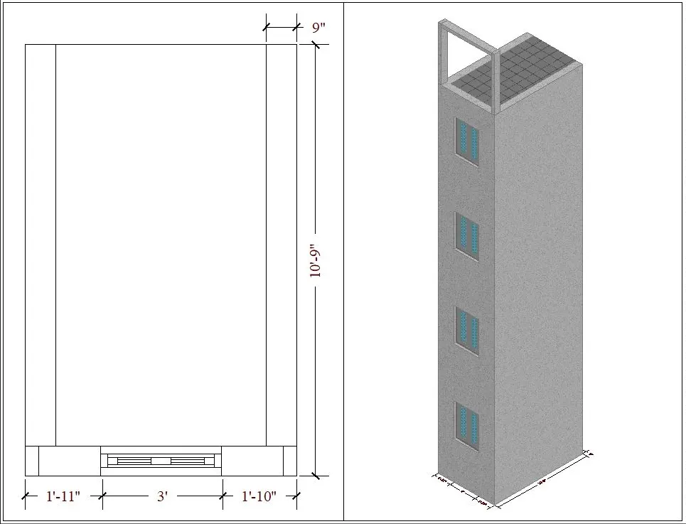
2. Create the 3D View of the Building Façade as given in the plan and elevation. Also, see the detail of the window.
Aim : To create the 3D view of the building facade as given in the plan and elevation and need to create the window using the given dimensions
Introduction :
- An isometric drawing is a 3D representation of an object , room , building or design on a 2D surface
- One of the defining characteristics of an isometric drawing ,compared to other types of 3D representation, is that the final image is not distorted
- This is due to the fact that the foreshortening of the axes is equal
- In an isometric drawing the object appears as if it is being viewed from above from one corner, with the axes being set out from this corner point
- Isometric drawing begin with one vertical line along which two points are defined
Commands used :
- Line command
- Rectangle command
- UCS command
- Dimlinear command
- Region command
- Extrude command
- Substract command
- Box command
- Units command
- Dimstyle command
- 3Dface command
- 3Dorbit command
- Hide command
- Explode command
- Move command
- Copy command
- Dist command
- Solidedit command
- Union command
- Boundary command
- 3D mirror command
- 3D rotate command
- Erase command
- Plan command
Procedure :
Step 1 :
- First we have to open the autocad and the set the maximum limit and minimum limit on the screen
- Here first have to draw the rectangle using the rectangle command
- Next we have to draw the window of size of 3'-2"x9"
Step 2 :
- Next we use the region command and select the object the press enter
- Then after total object will become the one region
- Next we need to extrude the plan using the extrude command with the height of 40'-10"
- Next we need to substract the four window portion vertically in a building facade with the distance 5'-11" with the window size of 3'x4'
Step 3 :
- Next we use the union command and press enter
- Then after select the total drawing and press enter
- Next the window portion will be clearly visible in the building facade
Step 4 :
- Next we select the custom visual style as shaded with edges
Step 5 :
- Next provide the layer for the building facade of skyblue colour
Step 6 :
- Next we close the top surface of the building facade using the using command
Step 7 :
- Next we draw the window of the size 3'-2'x4' as shown
- We draw the window using the line command and extruded using the extrude command
Step 8 :
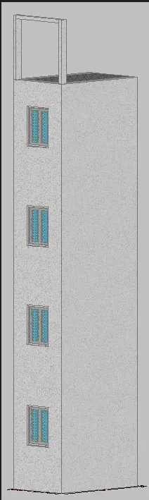
- Next we use 3Dorbit command to view the front elevation
Step 9 :
- Now put the building facade in the 3d isometeric view using the 3dorbit command
Result :
The given 3D isometeric view of the building facade is drawn successfully in the autocad in detailed manner
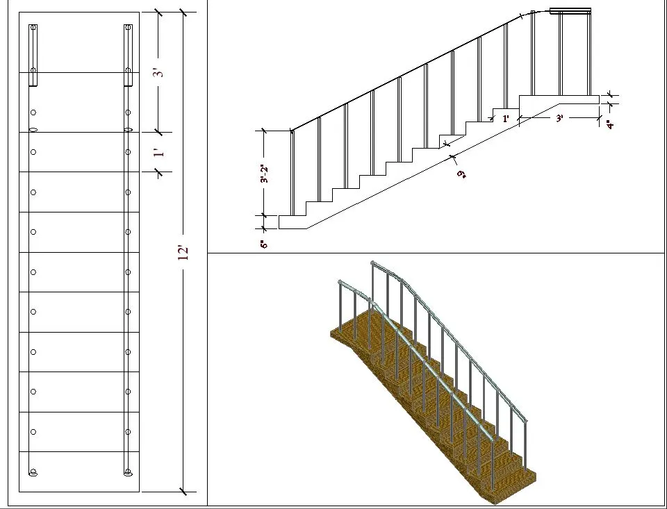
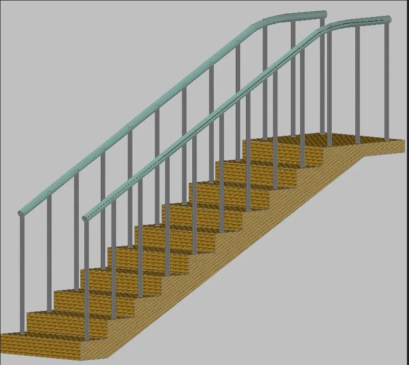
3. Create the ismoteric 3d view of a stair with railing as shown in the plan and elevation. Assume the size of the balustrades and the hand rails.
Aim : To create the isometeric 3Dmeteric view of a stair with railing as in the plan and elevation
Introcduction :
- An isometeric drawing is a 3D representation of an object ,room, building, stairs or design on a 2D surface
- One of the defining characteristics of an isometeric drawing ,compared to other types of 3D representation, is that the final image is not distorted
- This is due to the fact that the foreshortening of the axis is equal
- In an isometeric drawing, the object appears as if it is being viewed from above from one corner, with the axis being set out from this corner point
- Isometeric drawing begin with one vertical line along which two points are defined
Commands used :
- Line command
- Rectangle command
- UCS command
- Dimlinear command
- Region command
- Extrude command
- Substract command
- Box command
- Units command
- Dimstyle command
- 3D face command
- 3Dorbit command
- Hide command
- Explode command
- Move command
- Copy command
- Dist command
- solidedit command
- Union command
- Boundary command
- 3D mirror command
- 3D rotate command
- Erase command
- Plan command
- Circle command
- Sweep command
Procedure :
Step 1 :
- First we open the autocad and set the maximum limit and minimum limit
- Next we set the units as architectural and take the precsion as 0'-0"
- Next we draw the stairs using the line command
- We draw the stairs with the riser of 6" and tread of 1'
Step 2 :
- Next we use the 3D rotate to rotate the figure from the previous step
- Next we use the extrude command to extrude the rotate figure to form the stair in 3D view
Step 3 :
- Next we draw the railing using the circle command and sweep command
- Next w show the stairs in the side view using the 3D rotate command as in figure
Step 4 :
- Now put the stair in the 3D isometeric view using the 3D orbit command as shown in the figure
Result :
- The given 3D isometeric view of the stair is drawn successfully in the autocad in detailed manner
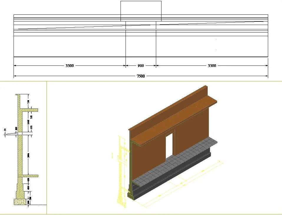
4 . Create the 3D view of a Wall with spread footing . Create the Door opening only. Assume the size of the parpaet and the coping. See the plans and elevation for the details. Also, create a rendered view of the model with materials as of your choice.
Aim : To create the 3D view of a wall with spread footing and need to create a rendered view of the model with materials
Introduction :
- An isometeric drawing is a 3D representation of an object, room, building , stairs or design on a 2D surface
- One of the defining characteristics of an isometeric drawing, compared to other types of 3D representation, is that the final image is not distorted
- This is due to the fact that the foreshortening of the axes is equal
- In an isometeric drawing , the object appears as if it is being viewed from above from one corner, with the axes being set out from this corner point
Commands used :
- Line command
- Rectangle command
- UCS command
- Dimlinear command
- Region command
- Extrude command
- Substract command
- Box command
- Units command
- Dimstyle command
- 3D face command
- 3D orbit command
- Hide command
- Explode command
- Move command
- Copy command
- Dist command
- Solidedit command
- Union command
- Boundary command
- 3D mirror command
- 3D rotate command
- Erase command
- Plan command
Procedure :
Step 1 :
- First we open the autocad and set the maximum limit and minimum limit
- Next we set the units as decimal and take the precision as 0
- Next we have to draw plan of wall with spread footing with given dimensions as shown
Step 2 :
- Next we draw the 3D isometeric view of the wall with spread footing using the extrude command as shown
Step 3 :
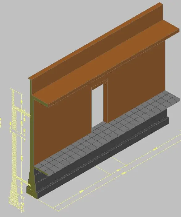
- Next provide the layer for the wall with spread footing with different colours for different parts, as shown
Step 4 :
- Next we provide the different materials for the wall with spread footing as shown
Step 5 :
- We select the camera and put it in the required position and then pess enter
- Next click on the camera the the small tab will appears at the top of the left corner as shown
Step 6 :
- Finally we select the render option and then slowly it changes to the rendering view is shown
Result :
The 3D view of the wall with spread footing and created a rendered view of the model with material successfully in the autocad in detail
Final Result :
- The 3D isometeric view of given drawing are drawn successfully in the autocad in detailed manner