Creating a Floor plan, Footing detail and Isometric view using AutoCad
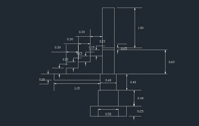
1. Cross sections of a load bearing wall over spread footing
Aim : To draw a crossection of wall over footing
Commands used :
- Line
- Rectangle
- Trim
- Dimension linear
Procedure :
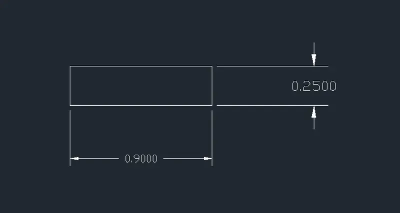
- Create a rectangle with a command of 'REC' in the command line
- Specify the first corner point as (1,1)
- specify the length of rectangle = 0.9 units in the command line
- Specify the width of rectangle =0.25 units in the command line
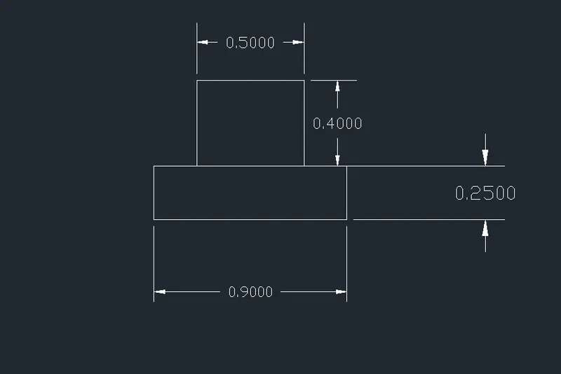
- create another rectangle with a command of 'REC' in command line
- Specify the first corner point which is 0.2 units from the starting point pf the first rectangle
- Enter the length of rectangle as 0.5 units the width of rectangle as 0.4 units
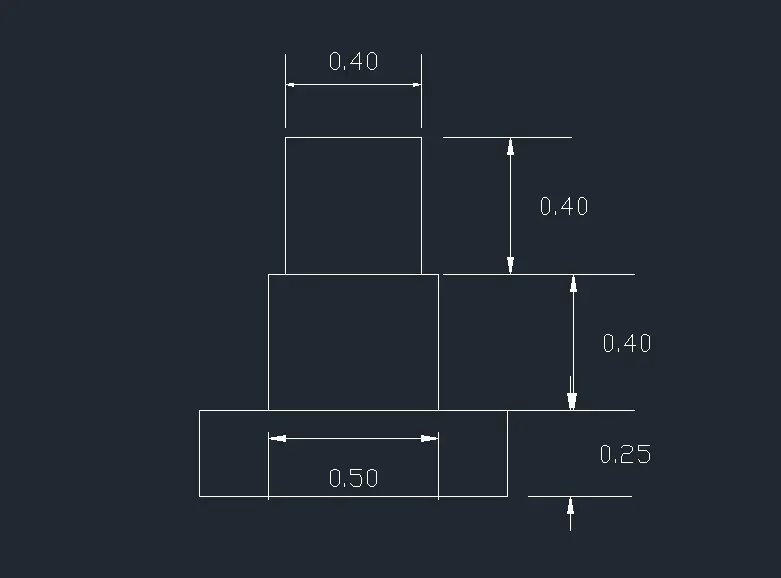
- Create the third rectangle with a command of 'REC' in command line
- Specify the first corner point which is 0.05 units from the starting point pf the first rectangle
- Enter the length of rectangle as 0.4 units the width of rectangle as 0.4 units
- Draw a line with length 1.15units from the corner of the third rectangle with a command "L" in the command line
- Place the cursor downwards and give a value of 0.15
- Place cursor right side and give a value pf 1.15
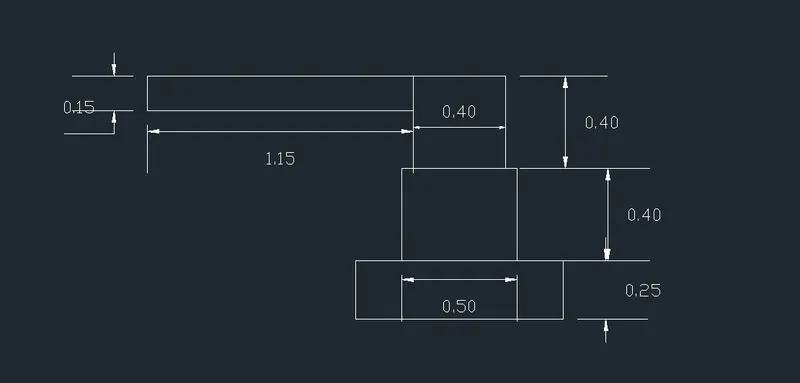
- Now the fourth rectangle is drawn with command "REC" in the command line
- Specify the first corner point at a distance of 0.05 from the third rectangle
- specifythe length as 0.3 units and width as 0.6 units
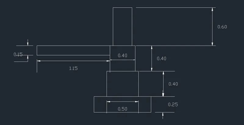
- From the corner point of the object created with a line command previously
- Draw a line with a command "L" in the command line
- draw a line at a distance of 0.3 units and place the cursor upwards and draw a line with a distance 0.15 units
- continue the same untill 3 more steps are created
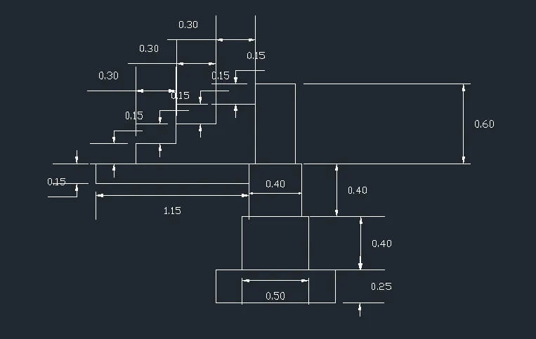
- Draw another rectangle with a command "REC" in the command line
- specify the corner point of the rectangle with the corner point of previous rectangle
- Specify the length as 0.3 units and width as 0.05 units
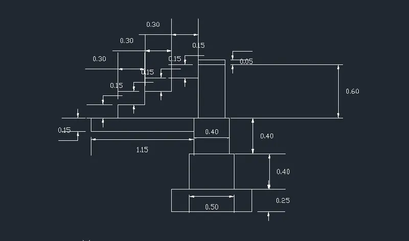
- Draw a fifth rectangle with command "REC" in the command line
- Specify the corner point of the rectangle with the previous rectangle corner point
- Specify the length as 0.3 units and width as 1 unit
RESULT :
The cross section of load bearing wall over spread footing is drawn
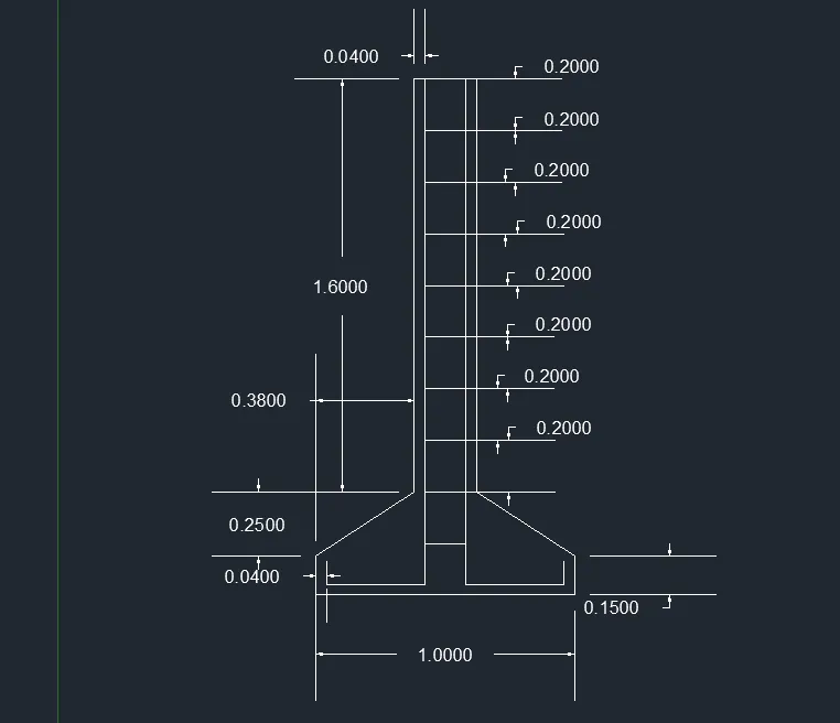
2. Cross section of an isolated footing
Aim : To draw cross section of an isolated footing
Commands used :
- Line
- Offset
- Trim
- Dimlinear
Procedure :
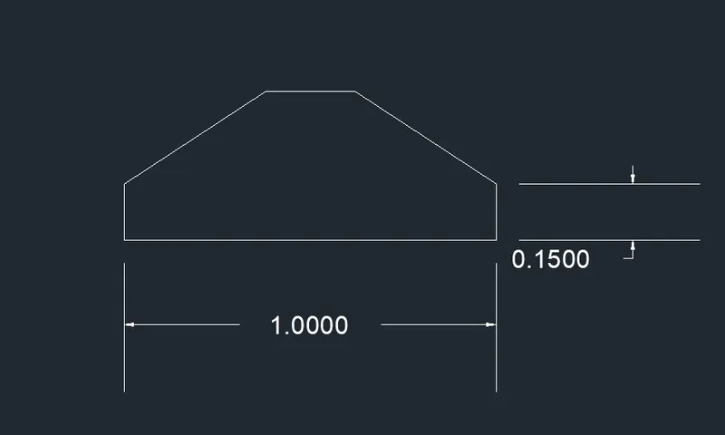
- Give a command as "REC" in the command line and press enter
- Specify the first corner point of the rectangle
- Enter "D" for dimensions
- Specify the length as 1 unit and width as 0.4 units
- Specify the other corner point of the rectangle

- Give a command as "CHA" or chamfer in the command line and press enter
- Enter "D" for distance
- Specify the first chamfer distance as 0.25
- specify the second chamfer distance as 0.38
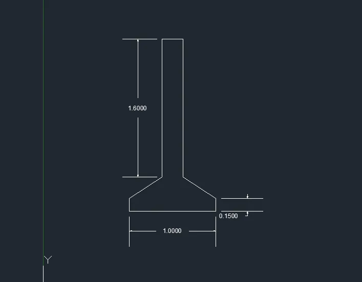
- Now give a command "L" in the command line and press enter
- Specify the top left corner point
- Specify the next coordinate point as @ 0,1.60
- Specify the next coordinate point as @ 0.24,0
- Specify the next coordinate point as @ 0,-1.60
- Now give a command "O" or "offset" in the command line and press enter
- Specify the distance of 0.04 with an offset value from the bottom line to upwards
- Give command of "o" and select the object and give the offset distance as 0.04
- Continue the same at the right and left bottom ends
- Trim the unwanted lines
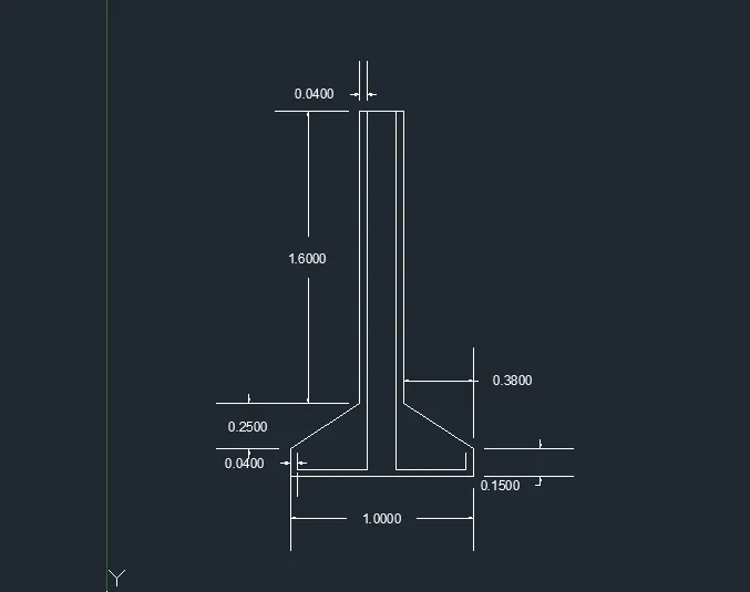
- Now give the offset from the top line with a offset distance of 0.2 units
- Give the command "O" and select the object with a given offset distance of 0.2 units
- Repeat the same downwards till the bottom line reaches the length
- Trim the unwanted lines
RESULT :
The cross section of the isolated footing is drawn
3. Line diagram of 2 bedroom buildings
Aim : To draw a line diagram of 2 bedroom buildings
Commands used :
- Line
- Rectangle
- Offset
- Trim
Procedure :
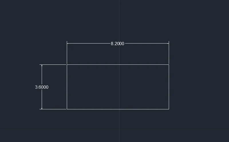
- Give a command "REC" or rectangle in the command line
- Specify the length as 8.2 units and width as 3.6 units
- Give the command "explode" and select the rectangle
- Now use the command "o" for the offset in the command line
- Specify the value as 3.6 units from left bottom
- Again use the command "o" for the offset in the command line
- Specify the value as 4.2 units from the right bottom
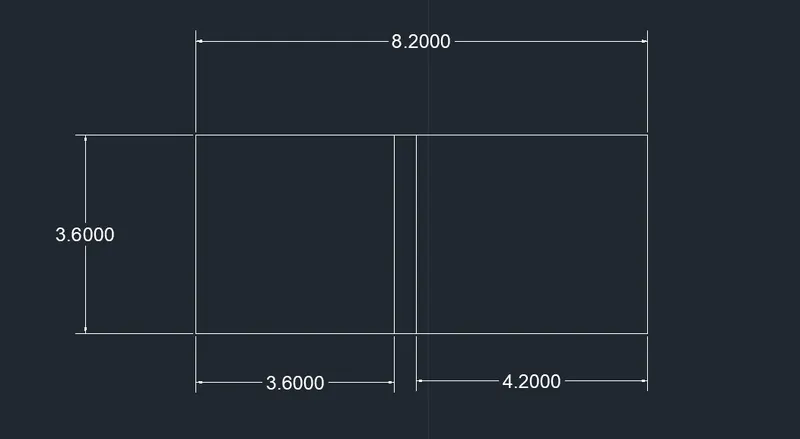
- Extend the two lines in the bottom and in the top
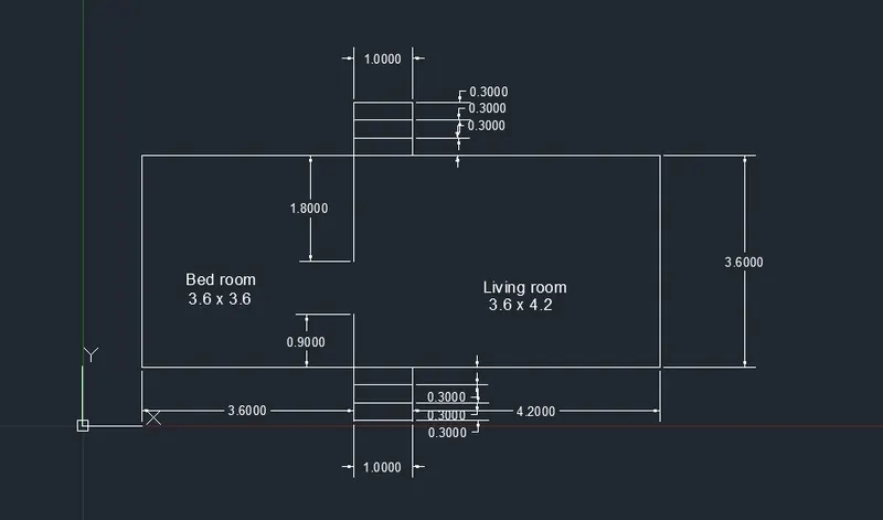
- Draw an offset at a distance of 0.3 units between the two line to bottom side
- Continue the same up to three offset lines on both top and bottom side
- earase the unwanted lines

- Use the line command "L" and draw a line with a distance of 3.6 units from the left bottom end to upwards with 0.9 units
- Use the line command "L" and draw a line with a distance of 3.6 units from the left top to downwards with 1.8 units
RESULT :
The line diagram of 2 bedroom building is drawn
4. Cross section of load bearing wall showing foundation details
Aim : To draw the cross section of load bearing wall showing foundation details
Commands used :
- Line
- Rectangle
- Trim
Procedure :
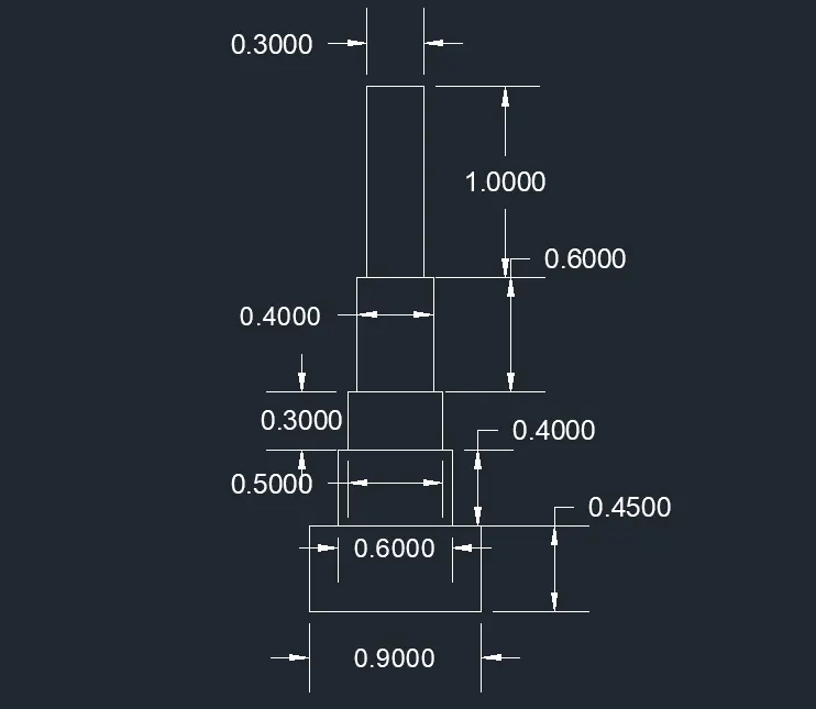
- Create rectangle with a command of "REC" in the command line
- Specify the first corner point of the rectangle as (5,5)
- Specify the length of rectangle as 0.9 units in the command line
- Specify the width of rectangle as 0.45 units in the command line
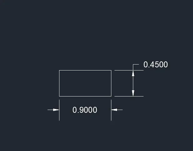
- Create another rectangle with a command of "REC" in the command line
- Specify the first corner point which is 0.15 units from the starting point of the first rectangle
- Specify the length of rectangle as 0.6 units and width as 0.4 units
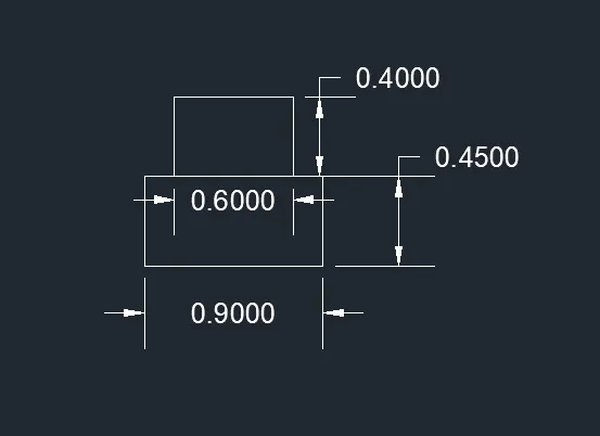
- Create the another rectangle with a command of "REC" in the command line
- Specify the first corner point which is 0.05 units from the starting point if second rectangle
- Specify the length of rectangle as 0.5 units and the width as 0.3 units
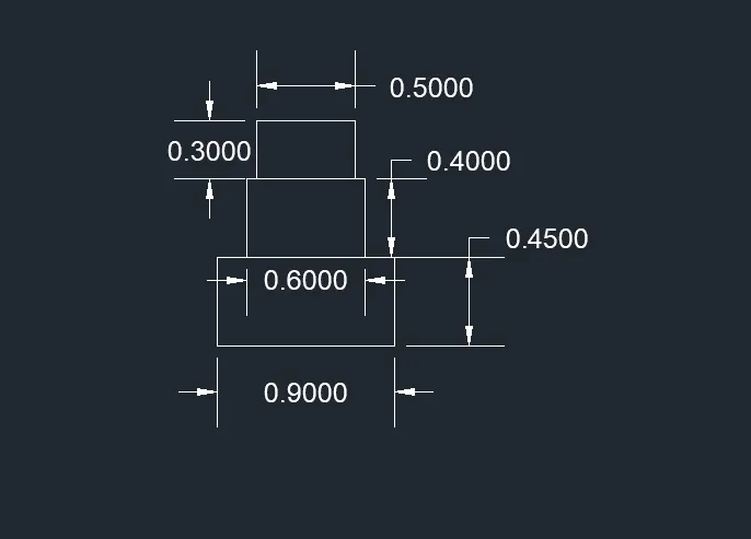
- Create the another rectangle with a command of "REC" in the command line
- Specify the first corner point which is 0.05 units from the starting point of third rectangle
- Specify the length of rectangle as 0.4 units and width as 0.6 units
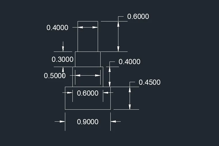
- Create the another rectangle with a command of "REC" in the command line
- Specify the first corner point of the rectangle
- Specify the length of the rectangle as 0.3 units and 1 unit
- Erase all the unwanted lines
RESULT :
The cross section of load bearing wall foundation details are drawn
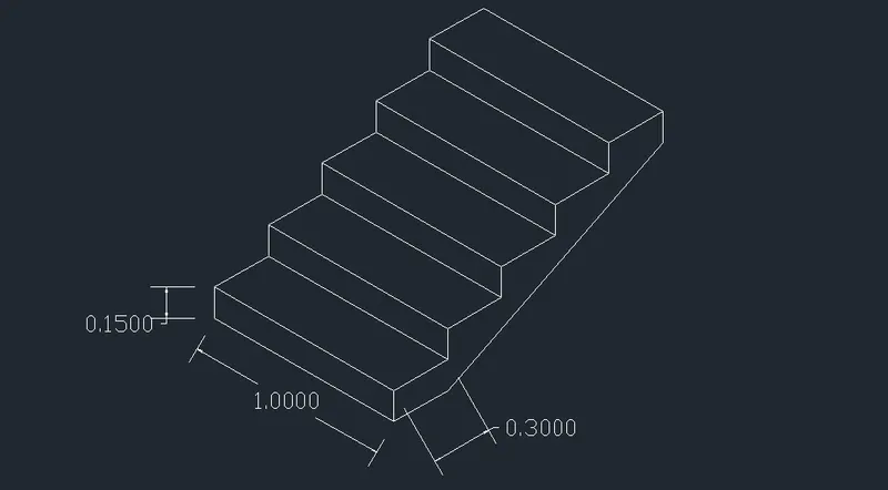
5. Isometric view of steps
Aim : To draw the isometric view of steps
Commands used :
- Line
- Isometric plane
Procedure :
- To work with isometric view give a command of "ds" to turn the snap off , grid off and put the isometric snap on
- Make sure that the ortho mode is on
- From isometric drafting select iso-plane left
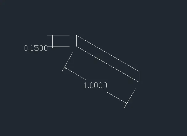
- Give a command of "L" from the command line and move the cursor to negative x-direction and give the value as 1 unit
- Move the cursor to positive y-direction and give 0.15 units
- Move the cursor to postive x-direcction again give 1 unit and move cursor to negavtive y-direction and give 0.15 units
- Change the isometric drafting to iso-plane top
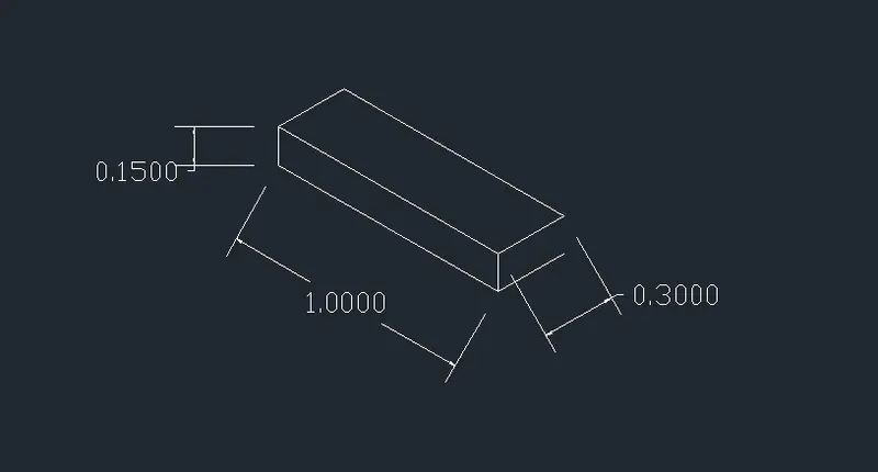
- Move the cursor to back and give the value as 0.3 units from the last drawn point
- Move the cursor to right direction and give 1 unit
- Move the cursor to front and give 0.3 units
- Change the isometric drafting to iso-plane right
- Copy the object drawn ,ortho off
- Give the command "co" in the command line and specify the base point and place it to new point
- Repeat it until 4 steps are formed
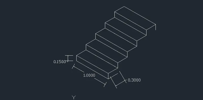
- With iso-plane right join the two ends woth ortho off
RESULT :
The steps are drawn in isometric view
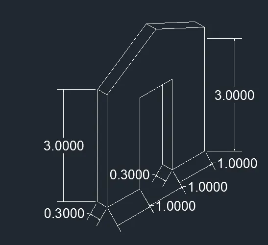
6. Isometric view of a gable wall
Aim : To draw the isometric view of a gable wall
Commands used :
- Line
- Isometric plane
Procedure :
- To work with isometric view give a command "ds" to turn the snap off , grid off and put the isometric snap on
- Make sure that ortho mode on
- From isometric drafting select iso-plane left
- Give the command as "L" in the command line and move the cursor to right and specify the value as 1 unit
- Place the cursor upwards give 3 units
- Draw 0.3 units to left and 3 units downwards and 0.3 units to left
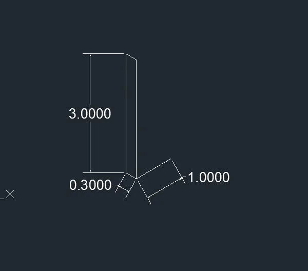
- Using the isometric right , take line command and draw the line upwards of 2.42 units from the staring point of previous one
- Draw 1 unit towards the right and 2.42 units downwards
- Using isometric left again, using line command draw 0.3 units to left side and draw a line which intersects the top line
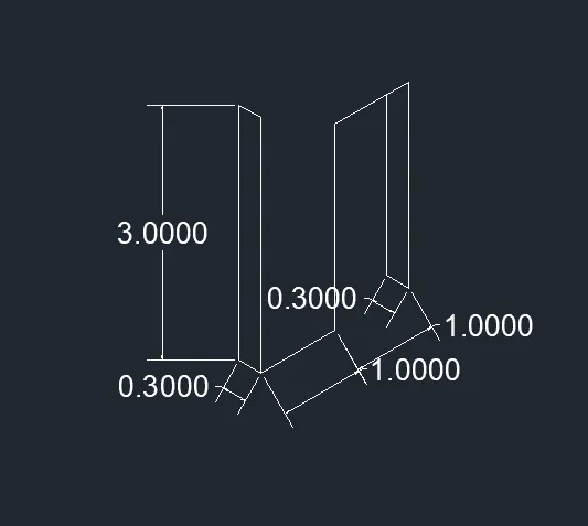
- Using the iso-plane right with the command "L" or line in the command line
- Draw 1 unit to the right side and 3 units upwards
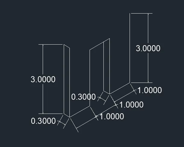
- By using the command "l" or line in the command line from the bottom left corner as 1.5 units
- Extend the line upto 4 units upward i,e... total 3.25 units from bottom
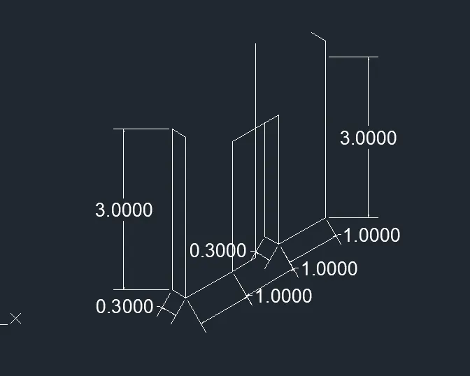
- With the ortho off , draw a line between the corner of left side and the projected line done in previous one
- Draw it to the other side also till it meets the right corner
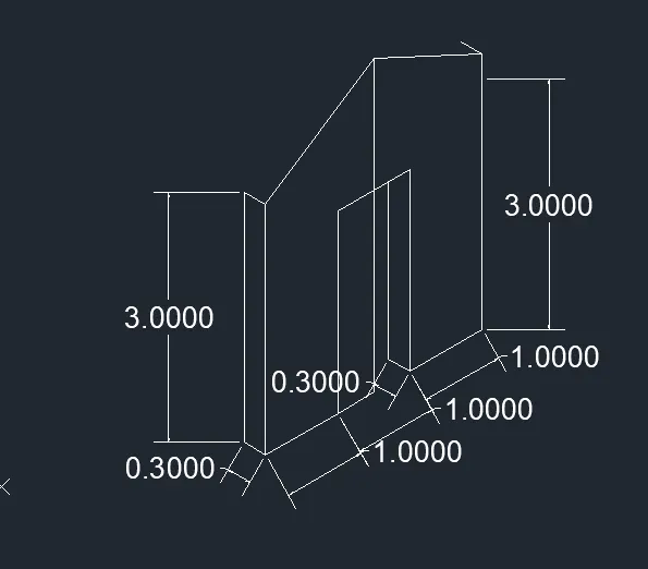
- Draw the vertical line with prtho on as 0.3 units
- Join the vertical line using line command from the left and right end which is same as in the previous one
- Ease the unwanted lines
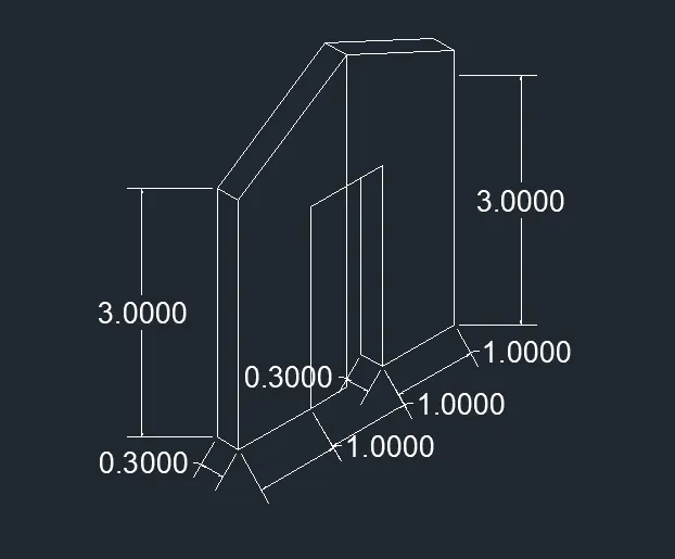
RESULT :
The isometric view of gable wall is drawn