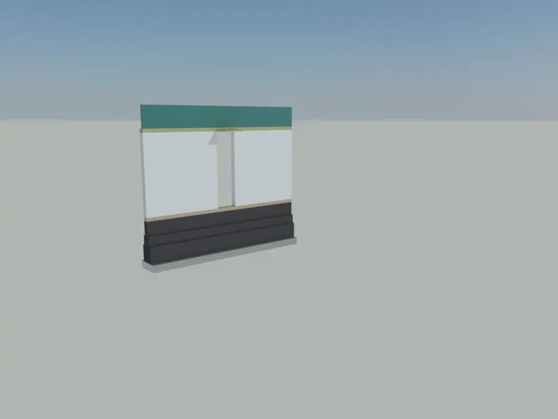
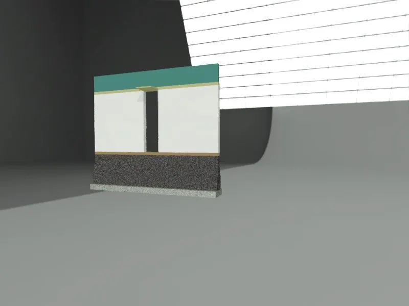
Creating 3D Isometric view of various structural elements in AutoCAD
Ans 1:
Aim: Create a 3D Isometric View of the building with plan and elevation given.
PROCEDURE:-
- Draw the plan with window.
- Use extrude command and extrude the walls.
- Use solidedit to creste face and extrude the windows.
- Draw the plan of windows.
- Rotate the windows using 3drotate.
- Now move the windows to the desired location
- Place it.
- Extrude the windows at desired dimension.
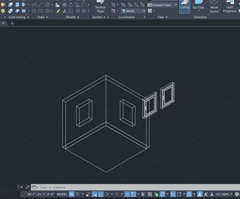
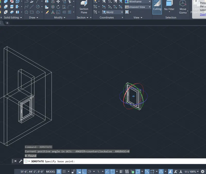
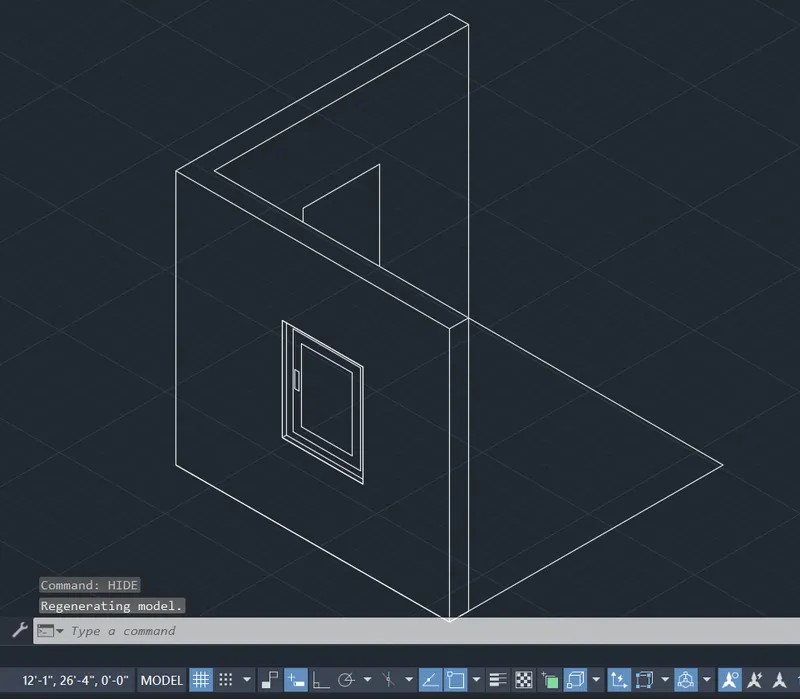
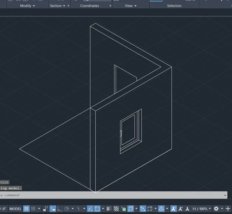
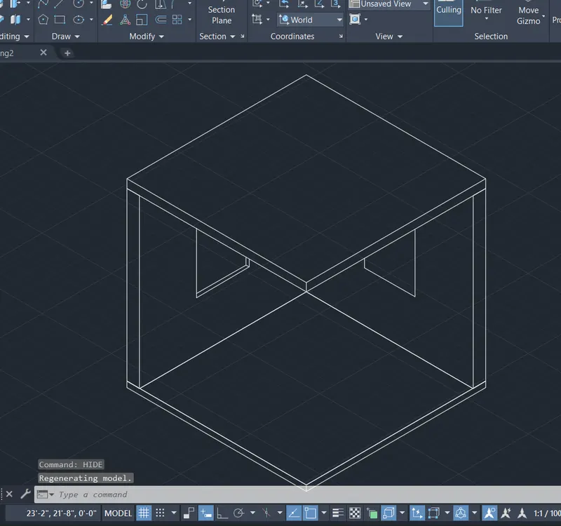
- Create a Face by soildedit and extrude the flooring.
- Create a face by solidedit and extrude the roofing
- Now move the flooring and roofing at the required position by move command.
Ans 2:
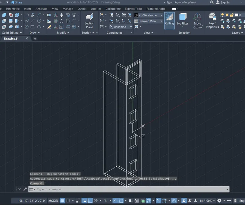
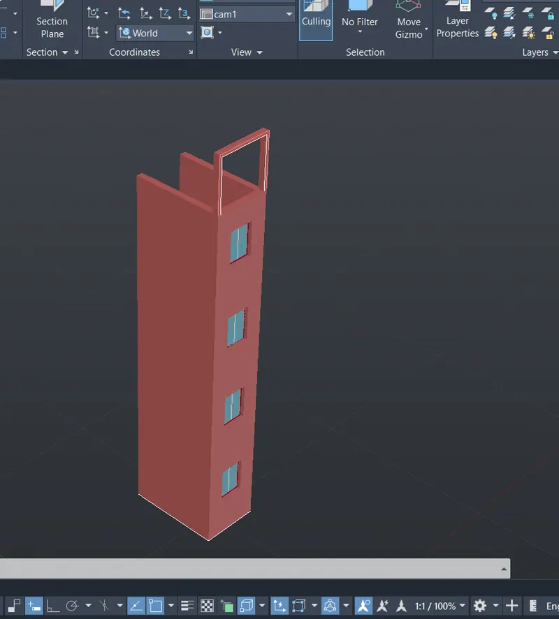
Aim: Create the 3D View of the Building Facade as given in the plan and elevation. Also, see the detail of the window.
PROCEDURE:-
- Draw the given Plan with window
- Extrude the the plan to the top height of the building
- Create a face for window.
- Copy the face to the different lintel levels of the building floor wise
- Now extrude the faces to create a wall and leave the area for the windows.
- Now change the view and create the projections above the building with given dimension.
- Extrude it at a given dimension.
- Now create the layers for different section wall, window glass, frame,mullion.
- Now draw the plan of window and extrude it and substract the different items.
- Apply layers to the window and walls
- Copy the windows and plave it at the required locations.
Ans 3:
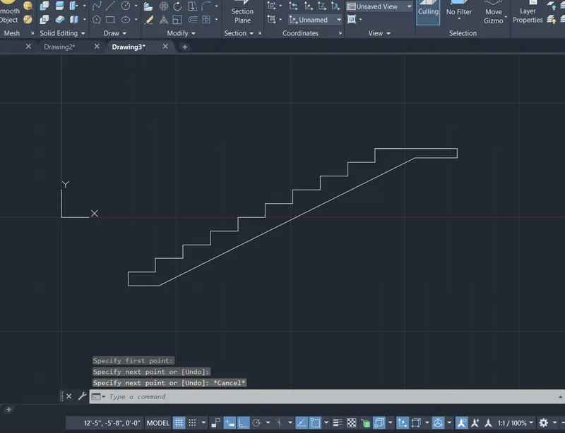
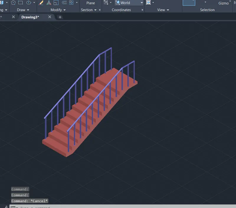
AIM: Create the ismoteric 3d view of a stair with railing as shown in the plan and elevation. Assume the size of the balustrades and the hand rails.
PROCEDURE:
- Draw the stairs with the riser of 6" and tread of 1' and aplatform of 3'.
- Next we use the extrude command to extrude the rotated figure to form the stair.
- Next we draw the railing using the circle command and sweep command by giving the line as the path
- Now mirror the stairs to form the railings at the both sides.
- Apply the layers .
AIM: To create the 3D view of a Wall with spread footing . Create the Door opening only. Assume the size of the parpaet and the coping. See the plans and elevation for the details. Also, create a rendered view of the model with materials as of your choice.
PROCEDURE:
- Draw the plan of the footings and walls as a rectangle.
- Extrude the footing upto floor levels.
- Now draw the plan of the section upto paraphet top.
- Rotate the plan using 3D view and plave it at the required location.
- Now extrude the walls and other sections upto door.
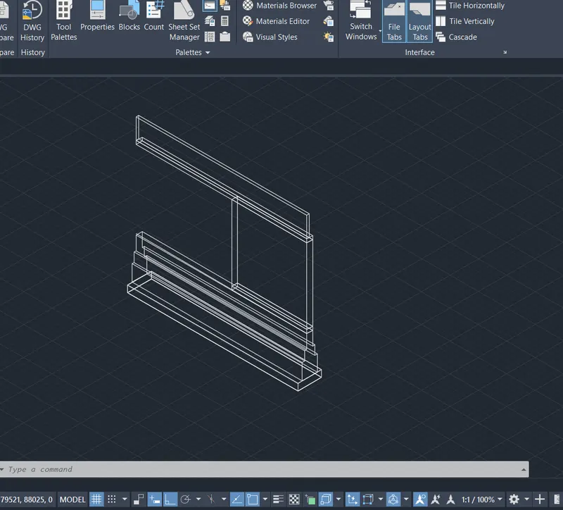
- create the face and copy it at a 900 distance.
- Now extrude the wall to the last end.
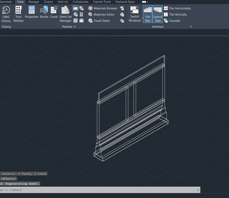
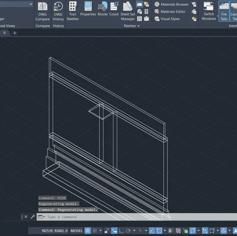
- Drwa the plan of chajja and rotate it using 3drotate copy it and place it at the required place.
- Extrude the chajja.
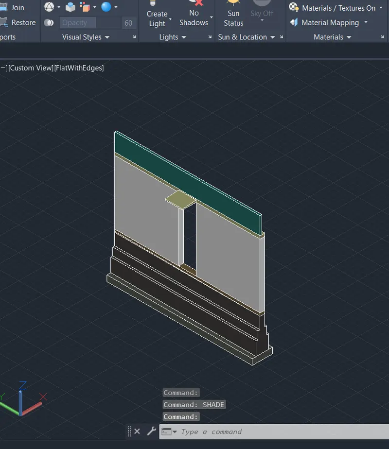
- Now provide materials to the different section and assign it
- Create a circle and extrude it and place the camera on the top of circle adjust it and set it as cam1 and cam2
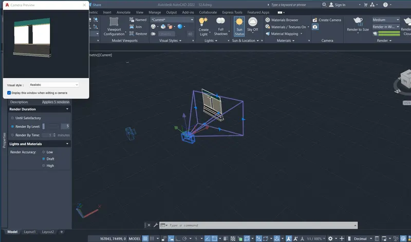
- now rendder it by viewports and the result will be shown.