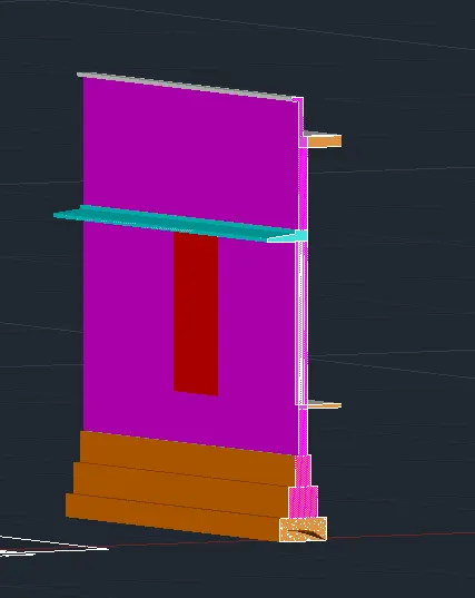
Creating 3D Isometric view of various structural elements in AutoCAD
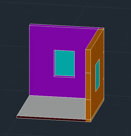
1. Create a 3D Isometric View of the building with plan and elevation given.
Procedure - Open Auto Cad 3D
Set top View
Set units Engineering and Inches and Set Limits.
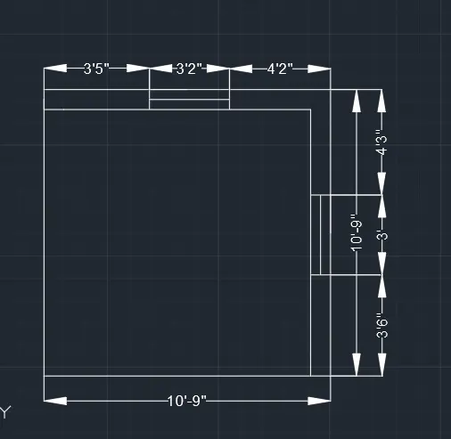
Now using rec command and draw rec size 10'9" x 10'9".
Now make a offset of 9" inside a sshown.
Now trim the both line and extend the line to outer rectangle.
Now draw window as shown.
Now by using 3D face command make 3D face to all.
Now extrude the walls and move the windows up as dimensions.
Now select any wall face and modify the window. Selct another wall face and modify the window.
Now apply layers and keep them in isometric view.
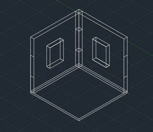
Fianl Result -
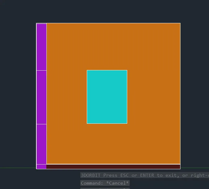
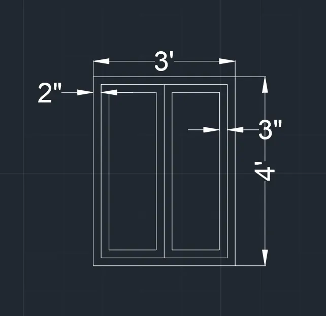
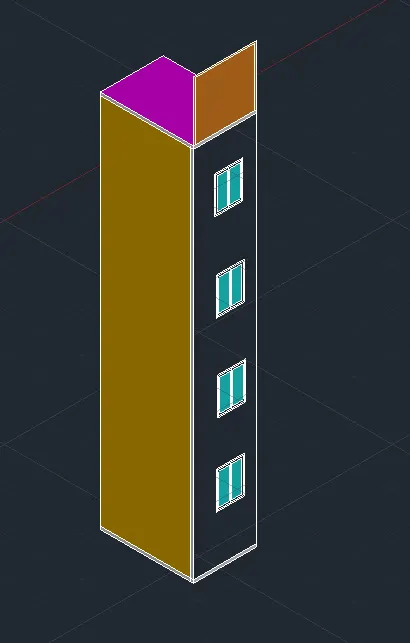
2. Create the 3D View of the Building Façade as given in the plan and elevation. Also, see the detail of the window.
Procedure - Open Auto Cad 3D
Set top View
Set units Engineering and Inches and Set Limits.
Now using rec command and draw rec size 10'9" x 6'9".
Now make a offset of 9" and trim the extra lines.
Now extend the trimmed line till the outer rectangle.
Now draw a window and give dimensions.
Now draw the detail window and give the dimensions.
Now extrude the drawn plane and keep it in front view and place this window and drawn at given as shown.
Now press home button near UCS to make it as isometric view.
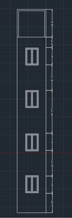
Detail Window -
Final Result -
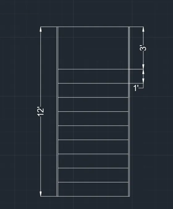
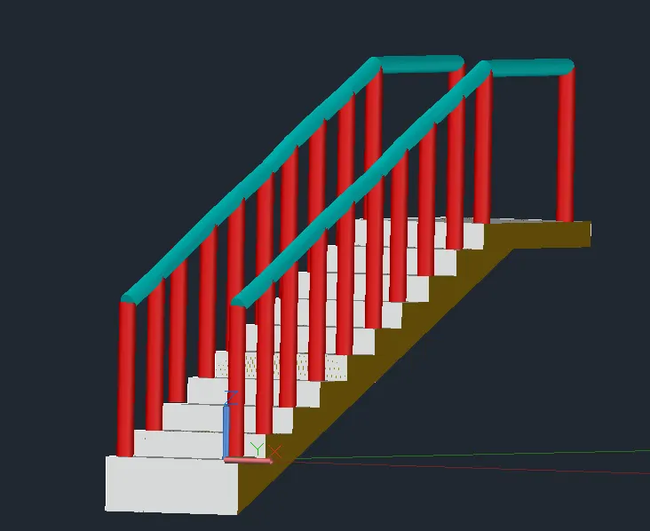
3. Create the ismoteric 3d view of a stair with railing as shown in the plan and elevation. Assume the size of the balustrades and the hand rails.
Procedure - Open Auto Cad 3D
Set top View
Set units Engineering and Inches and Set Limits.
Now using line command and draw line 12' vertically.
Now make a offset of 3' for the 12' line.
Now join the two vertical lines at a bottom with a horizontal lines.
Now make 9 offset line at 1' distance between each line.
Now after 9 offset make the offset ditsance to 3' and draw an offset.
Now give dimensions as shown.
Now remove the railing and keep it isometric view and extrude stairs as shown.
Now apply the layer.
Now by using the circle command and extrude the command , we draw the railing as shown.
Final Result -
4. Create the 3D view of a Wall with spread footing . Create the Door opening only. Assume the size of the parpaet and the coping. See the plans and elevation for the details. Also, create a rendered view of the model with materials as of your choice.
Procedure -
Open Auto Cad 3D
Set top View
Set units Decimal and mm and Set Limits.
Now using line command and draw line 7500 vertically.
Now make a offset of 670.
Now join two vertical lines in up and down using the horizontal lines.
Now make 3300 offset for horizontal lines in top and bottom.
Now make an offset for vertical lines as required.
Now Draw door as shown.
Now place this door in wall as shown.
Now hatch the wall as required and give the dimensions.
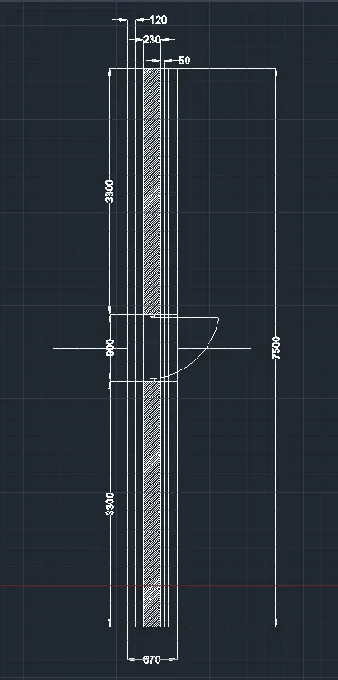
This is the top view.
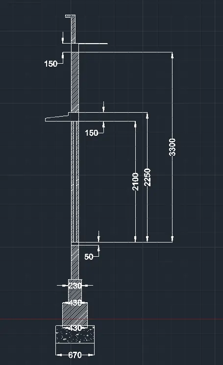
Now we are drafting the section of the wall footing.
Now by using line command and rectangle command the section of the wall footing is drawn.
Now give hatching where ever required.
Now give dimensions.
 \
\
Now keep in isometric view and extrude the section and apply the layers as shown.
Final Result -