Creating 3D Isometric view of various structural elements in AutoCAD
1)
AIM: To Create a 3D Isometric View of the building with plan and elevation given.
PROCEDURE:
- To draw the given diagram by 2D & 3D autocad tools.
- first we will use the absolute/rectangular coordinating method for drawing.
- after that we will use 3D tools wherever required.
- 3D ROTATE,EXTRUDE tools also used for the drawing the above diagram.
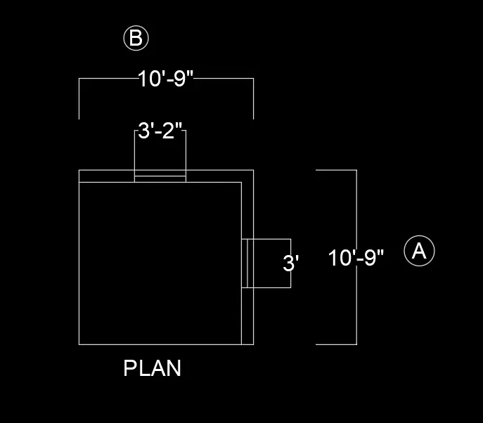
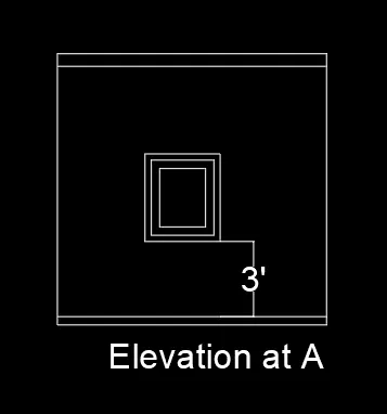
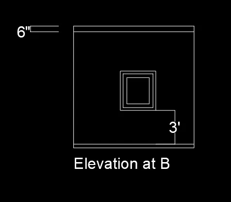
Result: I understand the how to draw the given diagram.
2)
AIM: To Create the 3D View of the Building Façade as given in the plan and elevation.
PROCEDURE:
- To draw the given diagram by 2D & 3D autocad tools.
- first we will use the absolute/rectangular coordinating method for drawing.
- after that we will use 3D tools wherever required.
- 3D ROTATE,EXTRUDE tools also used for the drawing the above diagram.
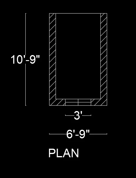
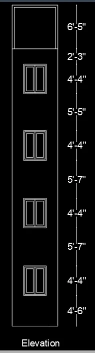
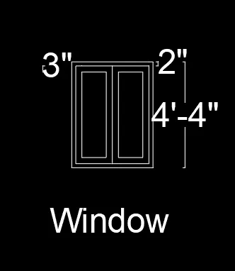
Result: I understand the how to draw the given diagram.
3)
AIM: To Create the ismoteric 3d view of a stair with railing as shown in the plan and elevation.
- To draw the given diagram by 2D & 3D autocad tools.
- first we will use the absolute/rectangular coordinating method for drawing.
- after that we will use 3D tools wherever required.
- 3D ROTATE,EXTRUDE tools also used for the drawing the above diagram.
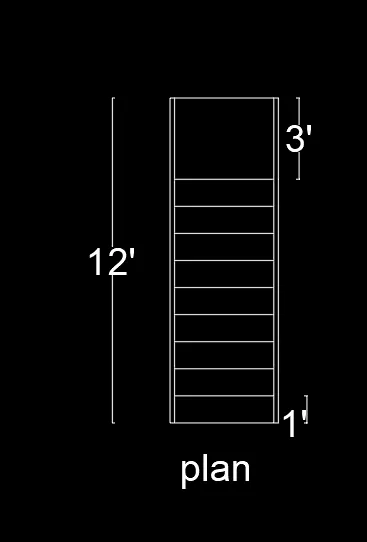
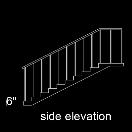
Result: I understand the how to draw the given diagram.
4)
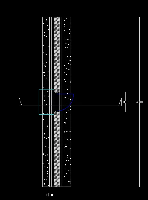
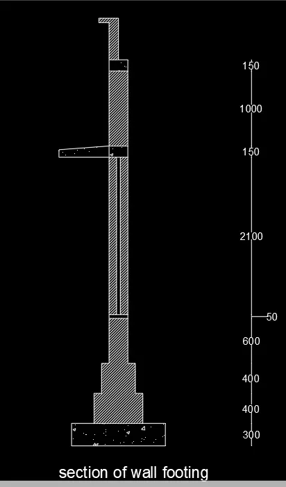
AIM: To Create the 3D view of a Wall with spread footing .
- To draw the given diagram by 2D & 3D autocad tools.
- first we will use the absolute/rectangular coordinating method for drawing.
- after that we will use 3D tools wherever required.
- 3D ROTATE,EXTRUDE tools also used for the drawing the above diagram.
Result: I understand the how to draw the given diagram.