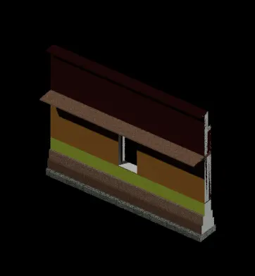
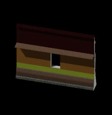
Creating 3D Isometric view of various structural elements in AutoCAD
1.Aim:
To create the 3D isometric view of a building with plan and elevation given:
Procedure:
*Initially, open the AutoCAD and go to 3D modelling.
*Then set the units of the drawing as engineering (feet and inches).
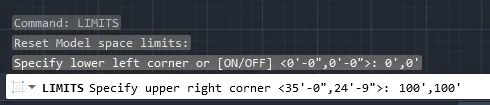
*Now set the limits:
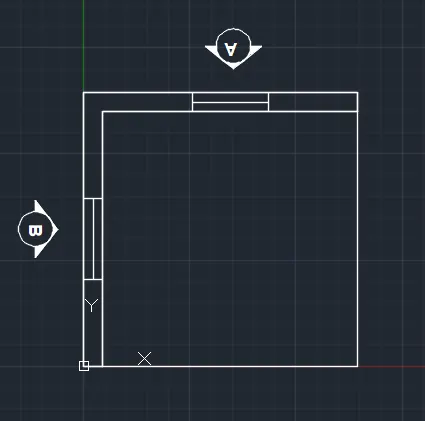
*Now, in the AutoCAD take the top view and intially draw the plan as given in the question.
*Using the line command the top plan is created as below:
*Now, using the dimlin command provide the dimension.
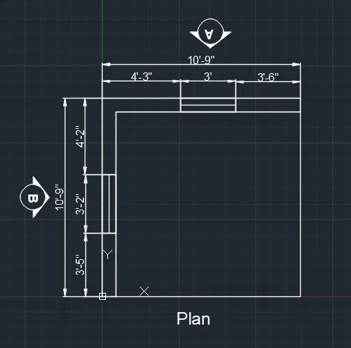
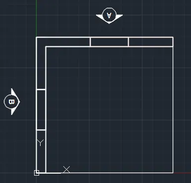
*Now hide the dimension layer.
*Then type BO command to create the boundary region for the walls and then extrude it.
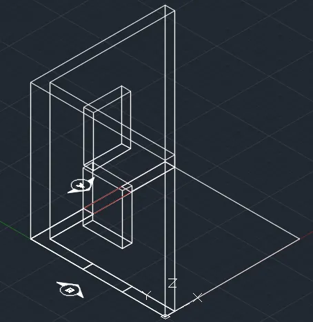
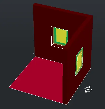
*Now, change the view to south west.
*Create the region and extrude it upwards at an extrusion height of 10'10".
*Then in the window portion of the plan create a rectangle and convert it into region and extrude it also to create a window in the wall.
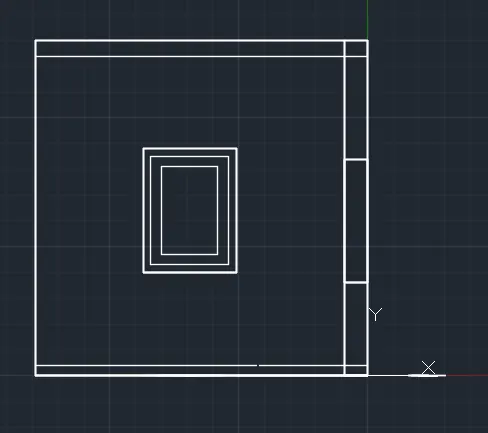
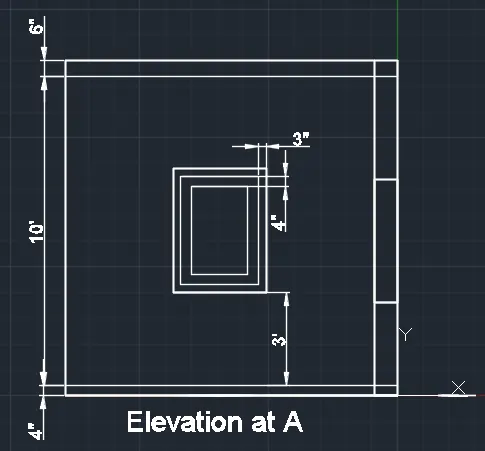
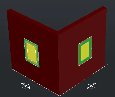
*Now, go to the backview and create the window using the rec command.
*This is elevation A.
*Now provide the dimensions.
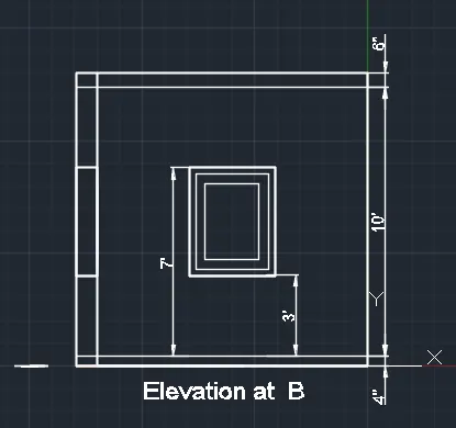
*Now, similarly draw the elevation at B by taking the right view.
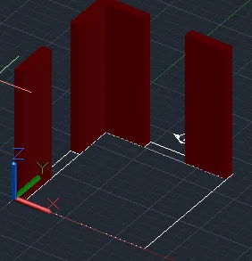
- Now, again go to top and assign layer to the walls.
- Then create the boundary region so thaat it can be extruded to create the 3D wall.
*Now, draw a rectangle at the window portion and create the boundary to it and then copy this rectangle vertically at adistance of 3'4" , 4' and 3'10".
*Then extrude this rectangle to complete the wall.
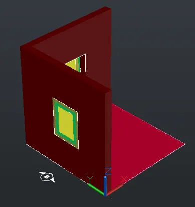
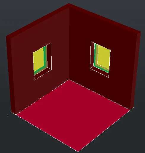
*Then provide the necessary hatching for the windows and the isometric view is completed.
Result:
2. Aim:
To create the 3D view of the building facade as given in the plan and elevation:
Procedure:
*Initially, open the AutoCAD and go to 3D modelling.
*Then set the units of the drawing as engineering (feet and inches).
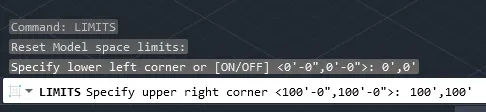
*Now set the limits:
*Now choose the line command and create the plan as gien in the question.
*Now, provide the hatch using the hatch command.
*Now using dimlin command provide the dimensions and using the mtext command provide the texts.
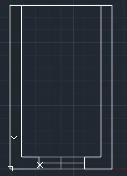
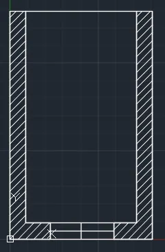
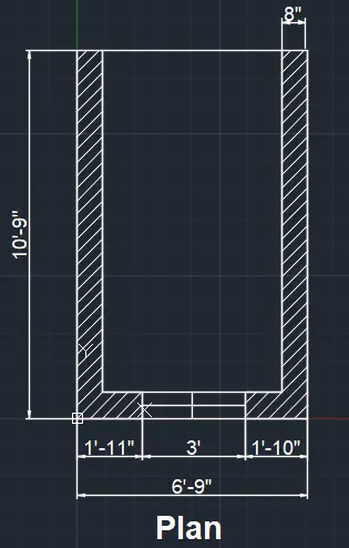
*Now hide the dimensions and texts and hatch to create the isometric view and elevation of the plan.
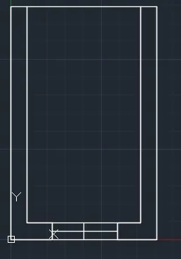
*So for that initially create the boundary region using the boundary command.
*Then extrude it upwards at a height of 40'10".
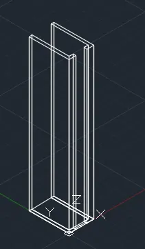
*Now create the windows at its required positions.
*Convert the figure to shaded view.
*Then draw a rectangle at the window position and convert it to a boundary region and then copy it to the window positions.
*Then extrude it to complete the 3D wall.
*Then using union command unite all the different components.
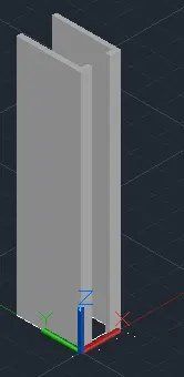
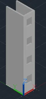
*Now, create the window separately in the right view and dimension it.
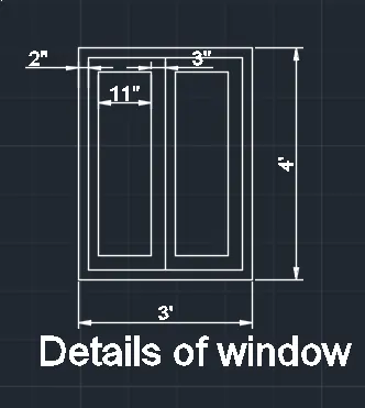
*Now hide the texts and dimensions and continue.
*Then using the command rotate 3D bring that window to the front view.
*Now place these windows in the front view of the structure created.
*Now, provide the dimensions.
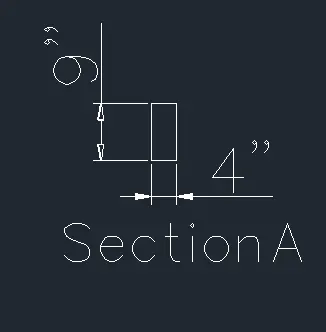
*Section A is drawn.


*Now we have to complete the isometric view of the given question.
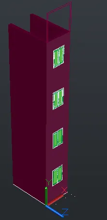
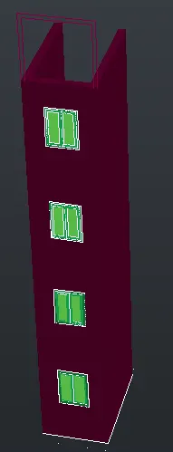
*For this hide the dimensions and texts and then change to south west view.
*Now assign layers to different components.
*Change the view to shaded.
Result:
3Aim:
To create the isometric 3d view of a stair with railing as shown in plan and elevation:
Procedure:
*Initially, open the AutoCAD and go to 3D modelling.
*Then set the units of the drawing as engineering (feet and inches).
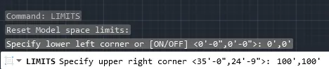
*Now set the limits:
*Initially using line command create the plan of the staircase.
*Then, provide necessary dimensions and texts.
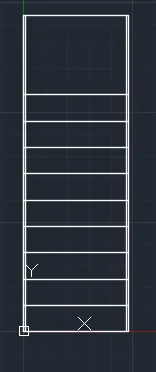
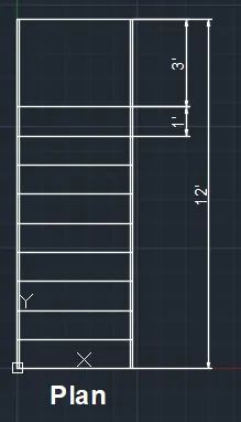
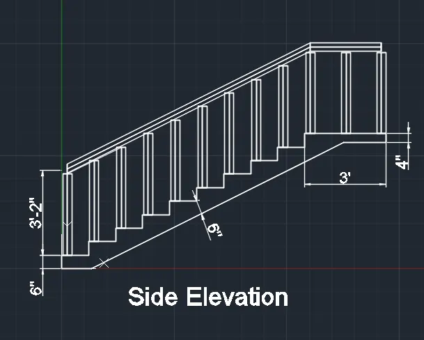
*Now, move to front view and create the side elevation of the staircase.
*This is done using the line command.
*The riser is taken as 6" and the thread is taken as 1'.
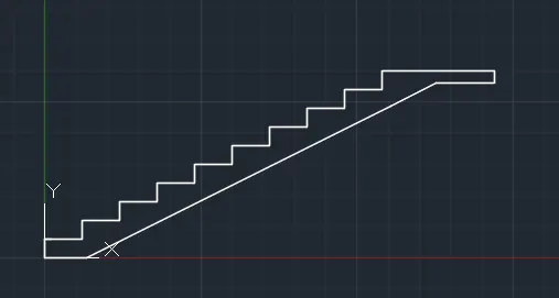
*Now, this portion is changed to a region.
*Then extrude it at a distance of 4'.
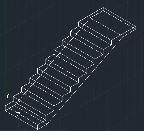
*The balustrade is created using circle of radius 2" which is then extruded upwads at a height of 3'.
*Similarly handrail is also created wit radius 2".
*Now, provide the necessary texts and dimensions.
*Now, we have to develop the isometric view of this staircase.
*For this, we have to first hide the texts and dimensions.
*Then change to south west view.
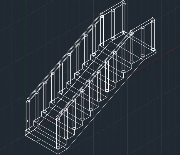
*Hidden view is :
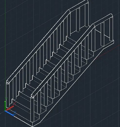
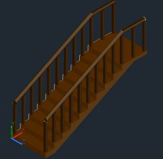
*Now assign layers to these staircases.
Result:
4Aim:
To create the3D view of a wall with spread footing, also create the rendered view of the model with materials of choice.
Procedure:
*Initially, open the AutoCAD and go to 3D modelling.
*Then set the units of the drawing as engineering (feet and inches).
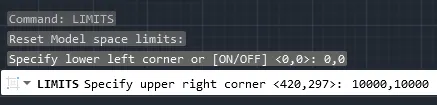
*Now set the limits:
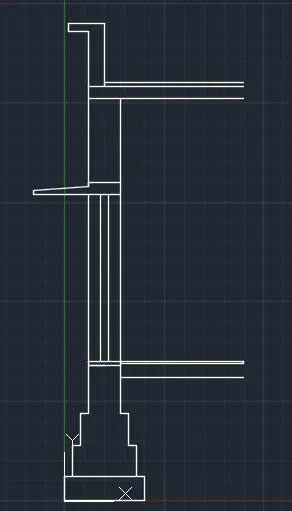
*Now, go to the front view and create the section of the wall footing.
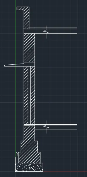
*Using the line command draw the given section.
*Then provide the appropriate hatchings using the hatch command.
*Provide the dimensions using dimlin command.
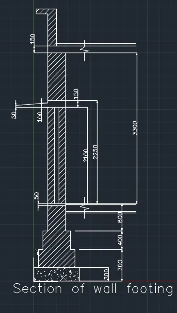
*Now after creating the section go to top view to create the plan.
*Then provide dimensions to complete the plan.
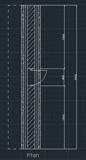
*Now, we have to develop the isometric view of the wall.
*For that, hide the dimensions, text and hatchings.
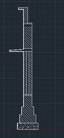
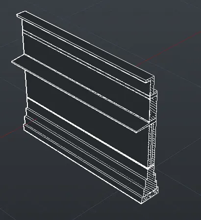
*Now, create the boundary region using the command BO.
*Then, extrude the created region to a extrusion height of 7500mm.
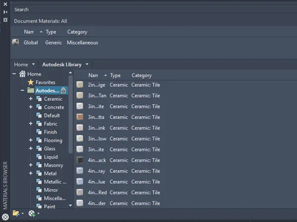
*Now, go to visualise tab of the ribbon and choose the material browser and then assign materials to each element.
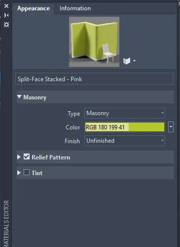
*After assigning materials the output obtained is:
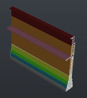
*Now, we have to create the door opening.
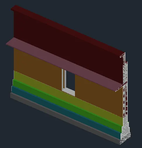
*Now we have to render this model.
*For this, go to visualise tab of the ribbon and in that choose render to size option and in that choose high quality rendering. Hence, rendering is done.
Result: