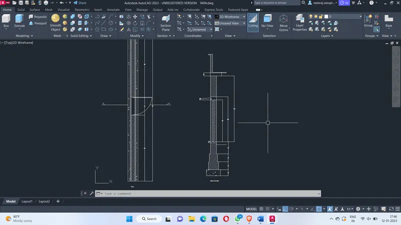
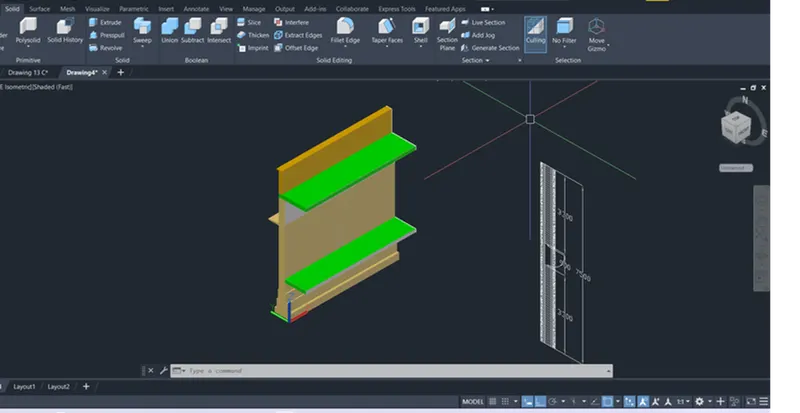
Creating 3D Isometric view of various structural elements in AutoCAD
1. Create a 3D Isometric View of the building with plan and elevation given.
Aim: To create a 3D isometric view of the building with plan and elevation
Introduction: AutoCad is a such software where we can draw a 2D and 3D drawing with such tools. The 2D drawing is converted into 3D. Such examples are given we are converting them into 2D view to 3D view.
Procedure:
Type UN in the command line and set the units into engineering
Set the precision as which you want
Type Limits in the command line
Set the lower limit and upper limit
Select 0,0 as lower limit and upper limit as 100,100
Type Z enter and A enter to fit the screen
Select the top view
Select the visuals as 2D wireframe
Draw the plan same as in the question given
And selecting the default view
Make a regions and extrude the regions with extrude command
The window is drawn with the specification same as in the questions
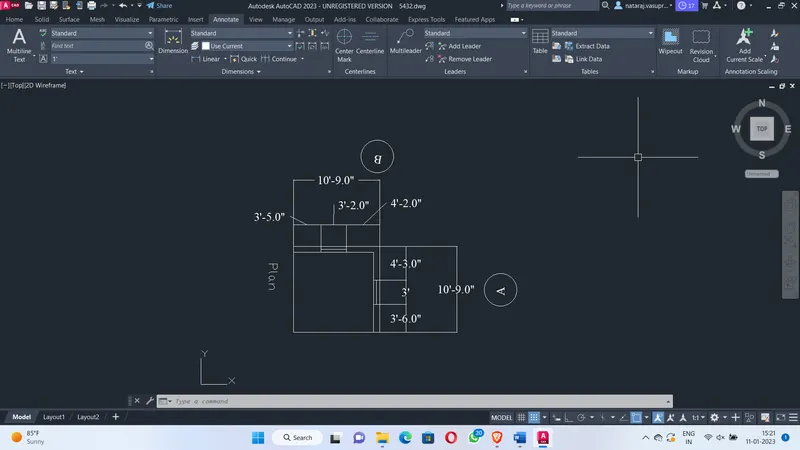
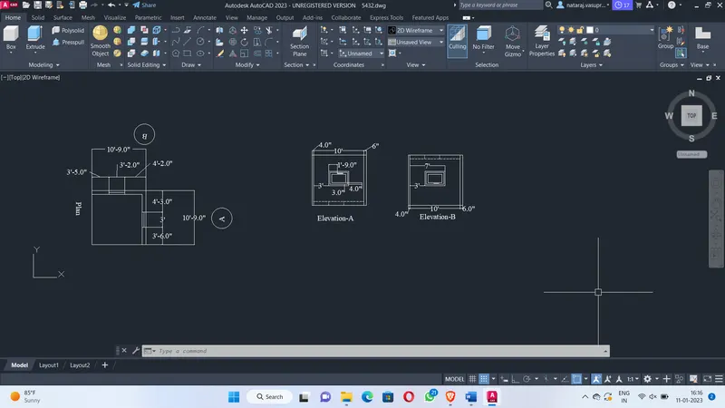
Result:
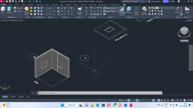
2Q
Aim: Creating the 3D View of the Building Façade as given in the plan and elevation. Also, see the detail of the window
Introduction: AutoCad is a such software where we can draw a 2D and 3D drawing with such tools. The 2D drawing is converted into 3D. Such examples are given we are converting them into 2D view to 3D view.
Procedure:
Type UN in the command line and set the units into engineering
Set the precision as which you want
Type Limits in the command line
Set the lower limit and upper limit
Select 0,0 as lower limit and upper limit as 50,50
Type Z enter and A enter to fit the screen
Select the top view
Select the visuals as 2D wireframe
Draw the plan of a building with the the help of line tool
And the dimensions are provided
The hatch is done to the drawing
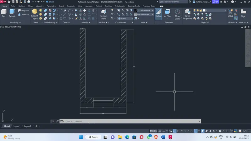
Now the regions are created with a tool boundary tool
The closed section is selected and now the regions are created
The regions are extruded with the help of extrude tool that is available in the 3D modelling
The windows are created with the help of drawing specification that are given in the question
And the whole drawing is converted into union
Result:
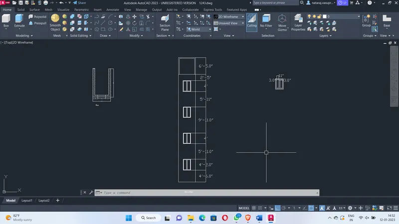
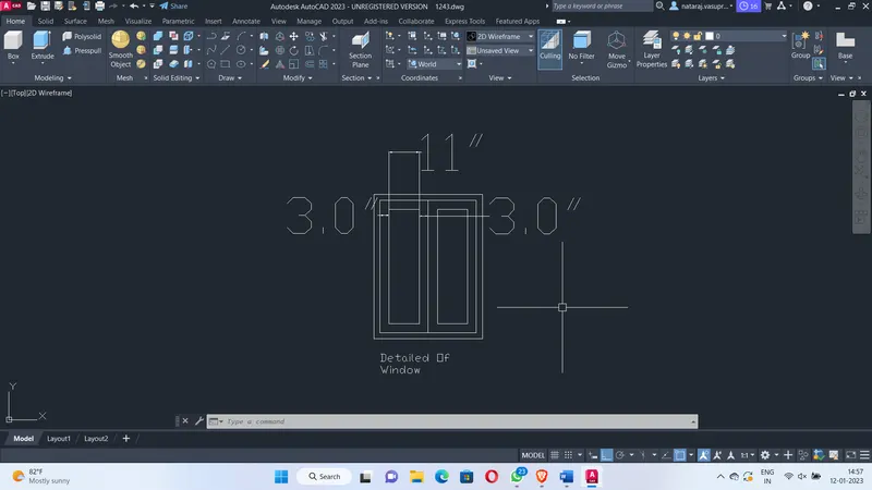
3Q
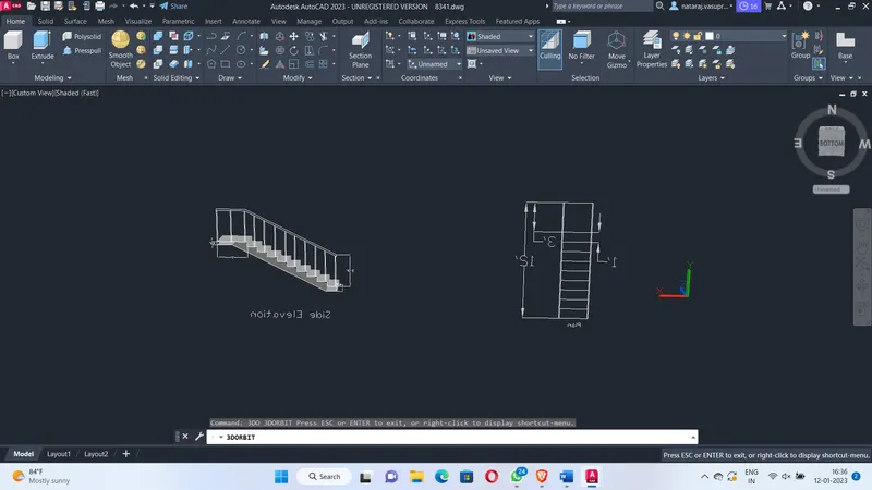
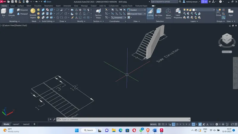
Aim: Creating the ismoteric 3d view of a stair with railing as shown in the plan and elevation. Assume the size of the balustrades and the hand rails
Introduction: AutoCad is a such software where we can draw a 2D and 3D drawing with such tools. The 2D drawing is converted into 3D. Such examples are given we are converting them into 2D view to 3D view.
Procedure:
Type UN in the command line and set the units into engineering
Set the precision as which you want
Type Limits in the command line
Set the lower limit and upper limit
Select 0,0 as lower limit and upper limit as 100,100
Type Z enter and A enter to fit the screen
Select the top view
Select the visuals as 2D wireframe
Draw the 2D wireframe drawing same as in the question with same specifications
By using line tool the drawing
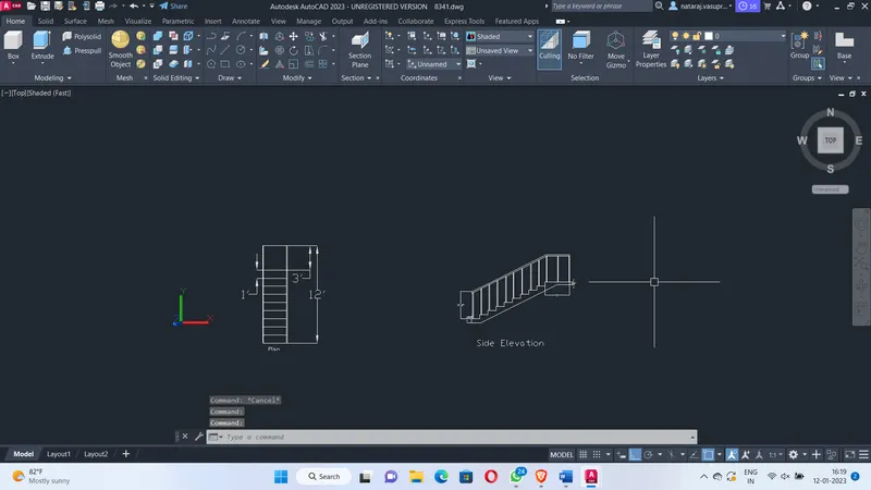
Now the tread and riser is created by riser is taken as 6" and tread is taken as 1'
Now copy the it upto 10 steps
Now type Ext in the command line
And extrude the stairs
Now draw a 1" diameter circle on the each surface of the tread
And extrude it upto 3'2"
Now draw a line by joining the top center point of the rails
And sweep the circle of 1" over that line
Select shaded visuals style
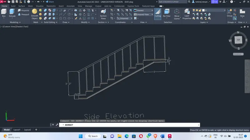
Now select a suitable colour to the stairs
Result
4Q
Aim: Creating the 3D view of a Wall with spread footing . Create the Door opening only. Assume the size of the parpaet and the coping. See the plans and elevation for the details. Also, create a rendered view of the model with materials as of your choice.
Introduction: AutoCad is a such software where we can draw a 2D and 3D drawing with such tools. The 2D drawing is converted into 3D. Such examples are given we are converting them into 2D view to 3D view.
Procedure:
Type UN in the command line and set the units into decimal
Set the precision as which you want
Type Limits in the command line
Set the lower limit and upper limit
Select 0,0 as lower limit and upper limit as 10000,10000
Type Z enter and A enter to fit the screen
Select the top view
Select the visuals as 2D wireframe
Draw the 2D wireframe drawing same as in the question with same specifications
By using line tool the drawing
Give the dimension by using dimlin command
Provide hatch to the drawing
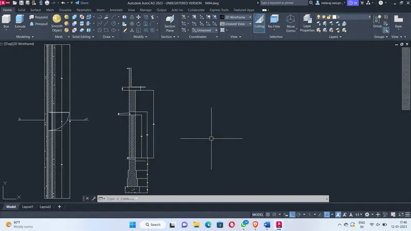
Now by using such command like extrude,region,boundary origin etc
The regions are created
Then the drawing is extruded
Now the suitable colour is added to the drawing
Result