Creating 3D Isometric view of various structural elements in AutoCAD
1.Aim:To create 3D isometric view of the plan and elevation
Procedure:
*Open Autocad set unit as feet or inches,
*Set lower left corner, upper right corner limits
Steps
1:Creating layers
2:Creating 3D view
3:Creating elevation windows
Window at elevation A
Window at elevation B
4.Creating views
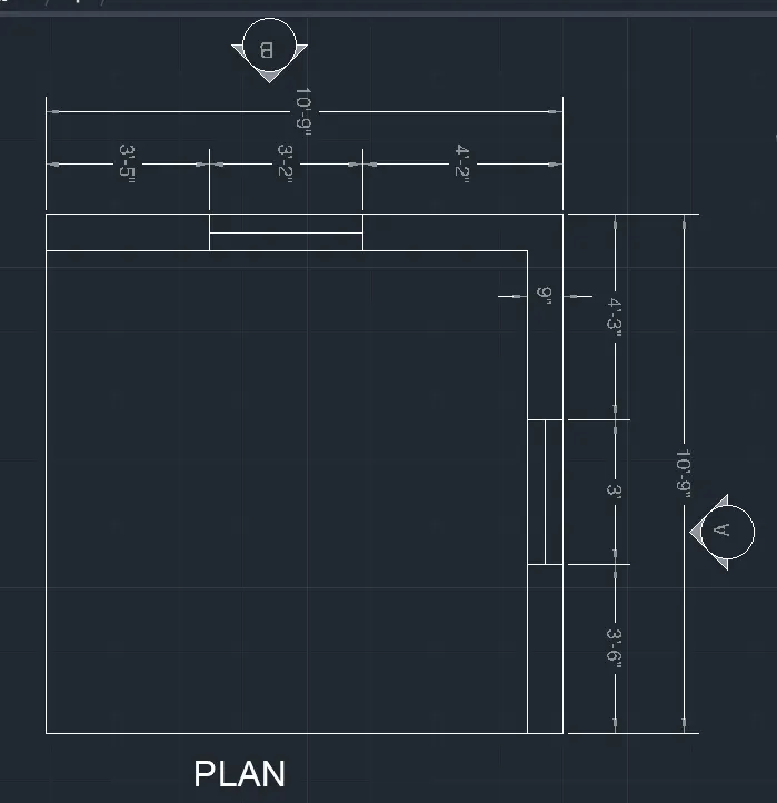
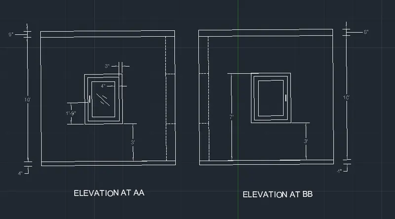
PLAN ELEVATION
2.Aim:3D view of building facade plan and elevation
Procedure:
*Open Autocad set unit as feet or inches,
*Set lower left corner, upper right corner limits
Steps
1:Creating layers
2:Creating 2D plan view
3.Creating 3D view
4:Creating elevation windows
*4' wide window
5.Creating elevation view
6.Creating view
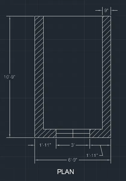
PLAN
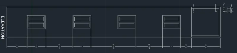
ELEVATION
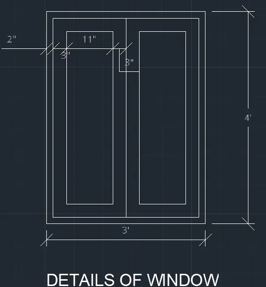
DETAILS OF WINDOW
3.Aim:To create the Isometric 3d view of stairs with railing
Procedure:
*Open Autocad set unit as feet or inches,
*Set lower left corner, upper right corner limits
Steps
1:Creating layers
2:Creating 2D plan view of staircase
3.Creating side view
4.Creating 3D view
5.Creating view
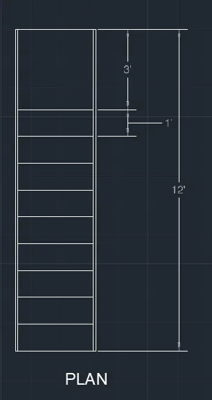
plan
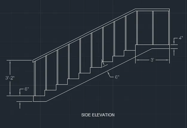
Side elevation
4.Aim: To create the 3D view of wall with spread footing
Procedure:
*Open Autocad set unit as feet or inches,
*Set lower left corner, upper right corner limits
Steps
1:Creating layers
2:Creating 2D plan view of wall with spread footing
Creating door block
3:Creating elevation view
Footing layers
4:Drawing 3D view section
Extruding
5:Rendering
Lights
6:creating views
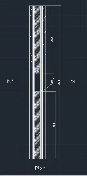
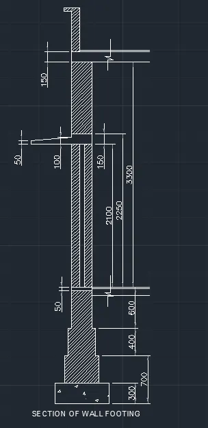
Plan Section of wall footing