Creating 3D Isometric view of various structural elements in AutoCAD
Commands Used in this challenge
• Line
• Rectangle
• Trim
• Move
• Copy
• Explode
• Circle
• Dimlinear
• Dimcontinue
• Boundary
• 3Dorbit
• 3D rotate
• Extrude
• Region
• UCS
• Camera
• Block
• Render RR
• Sweep
• Create Light
1. Create a 3D Isometric View of the building with plan and elevation given.
Aim: To draw the 3D Isometric View of the building as shown in the figure
Introduction:
A plan view of wall of two elevation views of windows on both sides are given and they are to be converted into a 3D model. 2 window openings on both sides are given with details regarding the frame dimensions, mullion dimensions and handle height. The thickness of bottom floor and top roof are also given as 4” and 6” respectively. The height of floor is given as 10’. Height of window from the floor is 3’.
Procedure:
Open AutoCAD
In Startup settings start from scratch select Imperial (Feet and Inches)
Open grid and snap settings
• Change snap and grid spacing to 1’
• Change major line every grid line to 10
• Turnoff adaptive grid
Type ‘un’ in command box and press enter
Change units’ type to decimal and precision to 1’1/16” and insertion scale to inches
Change the workspace setting of AutoCAD from ‘drafting and annotation’ to ‘3D Modeling’
Step 1: Creating Layers
Open Layer properties and create new layers by clicking on new layer or right click on any layer and select new layer to create new layer
Layers are created as follows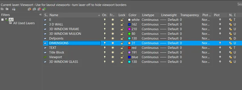
Step 2: Creating Layers
Change the current layer to 3D_Wall
• Create a rectangle of dimensions 10’9”X10’9” at any point on the screen
• Offset the rectangle to inside to distance of 9” as wall thickness
• Delete the left and bottom lines and extend them to the edges as shown in figure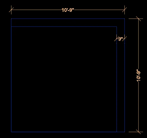
Change the current layer to 3D_Window_Frame
• Draw the window with dimensions 3'2" at top and 3' on right side as shown in figure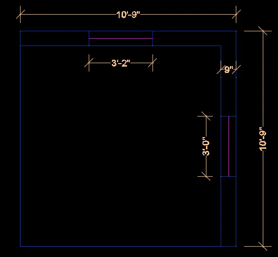
Step 3: Creating 3D View
Change the view to 3d by clicking on home button of view cube
Set UCS as world
• Create the boundaries for the walls using ‘BO’ command
• Extrude the boundaries created to total height of 10’10”
• Select all the wall and use group command to group then together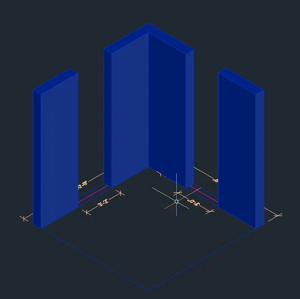
• Draw rectangles at both windows and change them to boundaries using boundary command
• Extrude both rectangles drawn to height of 3’4” as shown in the figure
• Draw rectangles at top of both window openings and change them to boundaries using boundary command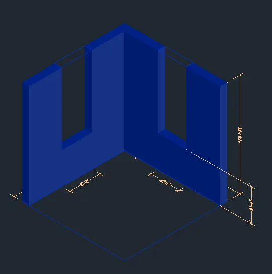
Type UCS and click on face and select the face having 3’ wide window
• Draw a rectangle from bottom part of window with dimensions @3’,4’
Type UCS and click on face and select the face having 3’2” wide window
• Draw a rectangle from bottom part of window with dimensions @3’2”,4’
Change the ucs back to world
• Extrude the rectangle drawn at top side to top edge of window
• Group all the wall components together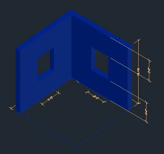
Step 4: Creating Elevation Windows
Window at Elevation A
Change the current layer to 3D_Window_Frame
Type UCS and click on face and select the face having 3’ wide window
• Draw a rectangle of dimension @3’,4’
• Offset the rectangle to inside to distnce of 3”
• Offset the offset rectangle to inside to distnce of 4”
Start the boundary command and click on pick points
• Click inside the window frame area and press enter
Start SUBTRACT command
• Select the bigger region and then select the smaller regions to subtarct them
Follow the same procedure for all the three boxes as shown in figure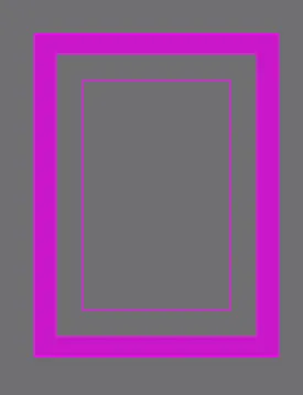
Change the current layer to 3D_Window_Mulion
Start the boundary command and click on pick points
• Click inside the window Mulion area and press enter
Start SUBTRACT command
• Select the bigger region and then select the smaller glass region to subtarct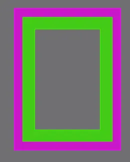
Change the current layer to 3D_Window_Glass
Start the boundary command and click on pick points
• Click inside the window glass area and press enter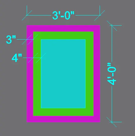
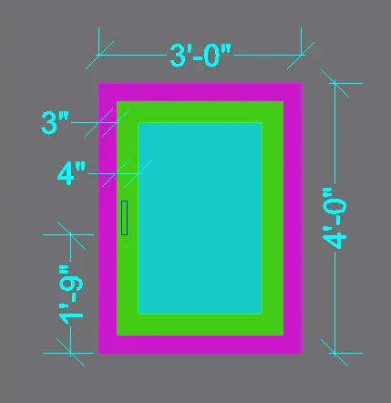
All the layers are extruded to give window projection look as shown in figure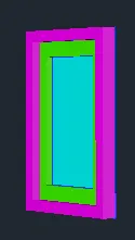
Window at Elevation B
Type UCS and click on face and select the face having 3’2" wide window
• Draw a rectangle of dimension @3’2",4’
• Offset the rectangle to inside to distnce of 3”
• Offset the offset rectangle to inside to distnce of 4”
Change the layer for all the boxes respectively
Start the boundary command and click on pick points
• Click inside the window frame area and press enter
Start SUBTRACT command
• Select the bigger region and then select the smaller regions to subtract them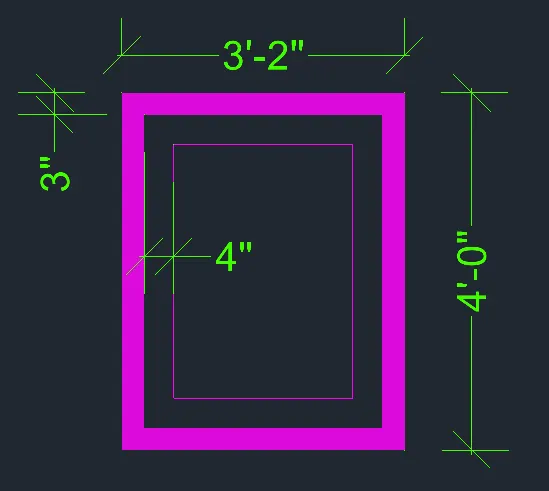
Change the current layer to 3D_Window_Mulion
Start the boundary command and click on pick points
• Click inside the window Mulion area and press enter
Start SUBTRACT command
• Select the bigger region and then select the smaller glass region to subtract it
Change the current layer to 3D_Window_Glass
Start the boundary command and click on pick points
• Click inside the window glass area and press enter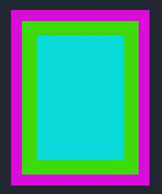
All the layers are extruded to give window projection look as shown in figure
Step 5: Creating Views
Click on home button of the view cube and zoom for better view
Go to visualzse tab and click on new view
• Set view name as VIEW 1
• Click on current view and press ok
Click on the NE isometric view of the view cube and zoom for better view
Go to visuvilise tab and click on new view
• Set view name as VIEW 2
• Click on current view and press ok
Click on the Top view of the view cube and zoom for better view
Go to visuvilise tab and click on new view
• Set view name as VIEW 3
• Click on current view and press ok
Result:
Initially all the layers necessary are created with respective line types and line weights. Then plan view is drawn as shown in step 2. Then from step 3 the 3D view is created with respective layers assigned. The UCS view is changed accordingly to make changes to the 3D view and 3D dimensions.Boundary command is used for creating regions along the boundaries and extruding them. After this view are created for showing result.The result consists of different views of the 3D model such as top view(View 3), SW isometric(View 1), NE isometric(View 2)
• All dimensions are in Feet and Inches
• Text and dimensions are added with respective layers
1. View 1(SW isometric)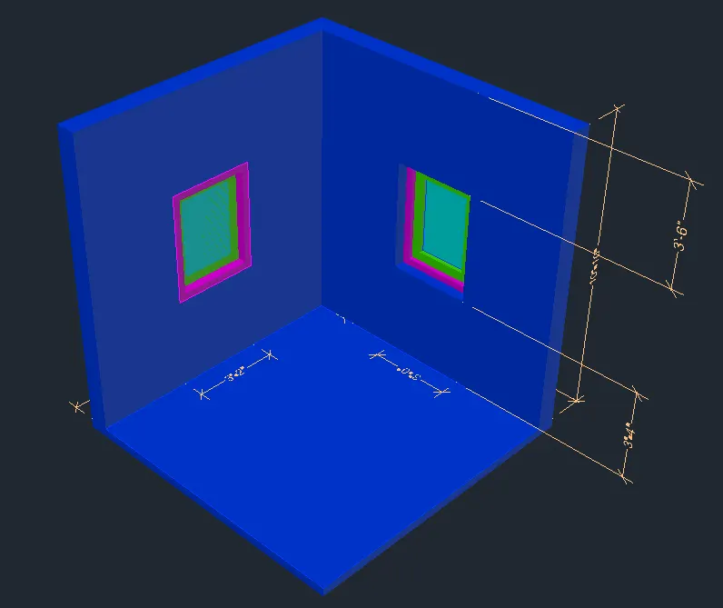
2.View 2(NE isometric)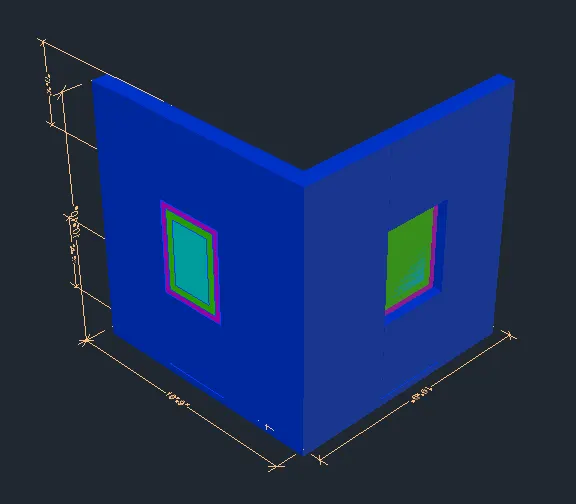
3. View 3(top view)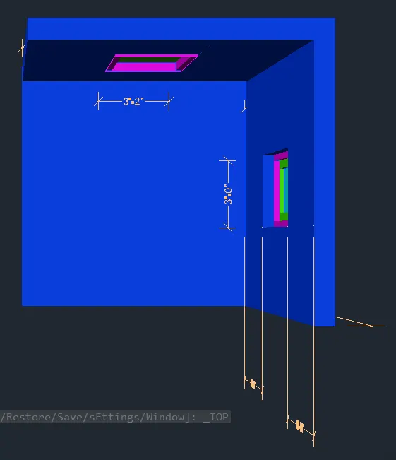
2. Create the 3D View of the Building Façade as given in the plan and elevation. Also, see the detail of the window.
Aim: To draw the 3D Building Façade as given in the plan and elevation
Introduction:
A plan view of wall and two elevation views, one is of a window details and second is of floor level elevations are given and they are to be converted into a 3D model. One window opening on front side is given with details regarding the frame dimensions, two mullion dimensions. The height of floor is given as 9’11”. Four floor building with similar dimension is made in 3D view. Height of window from the floor level of each floor is given as 4’6”.
Procedure:
Open AutoCAD
In Startup settings start from scratch select Imperial (Feet and Inches)
Open grid and snap settings
• Change snap and grid spacing to 1’
• Change major line every grid line to 10
• Turnoff adaptive grid
Type ‘un’ in command box and press enter
Change units’ type to decimal and precision to 1’1/16” and insertion scale to inches
Change the workspace setting of AutoCAD from ‘drafting and annotation’ to ‘3D Modeling’
Step 1: Creating Layers
Open Layer properties and create new layers by clicking on new layer or right click on any layer and select new layer to create new layer
Layers are created as follows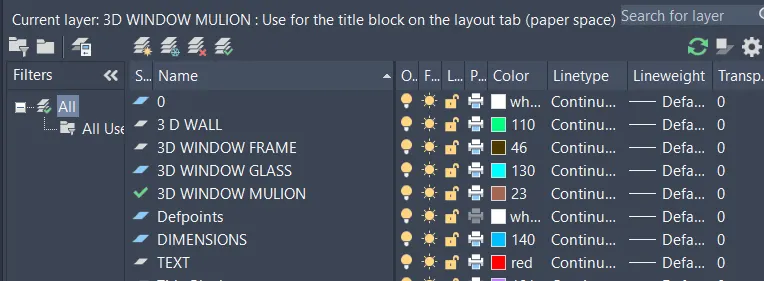
Step 2: Creating 2D Plan View
• Create a rectangle of dimensions 6’9”X10’9” at any point on the screen
• Offset the rectangle to inside to distance of 9” as wall thickness
• Explode the rectangles drawn
• Delete the top line and extend them to the edges
Change the current layer 3D_Window_Frame
• Create the window opening of dimensions 3’ wide as shown in figure
• Add dimensions are drawn using dimension layer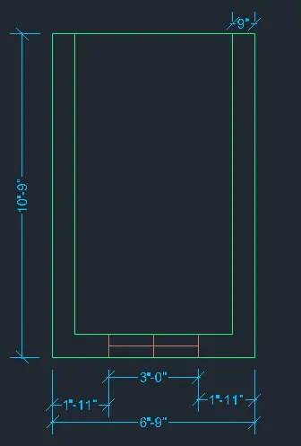
Step 3: Creating 3D View
Change the view to 3d by clicking on home button of view cube
Set UCS as world
Set the view style control as REALISTIC
• Create the boundaries for the walls using ‘BO’ command
• Extrude the boundaries created to total height of 10’10”
• Select all the wall and use group command to group then together
• Delete the window lines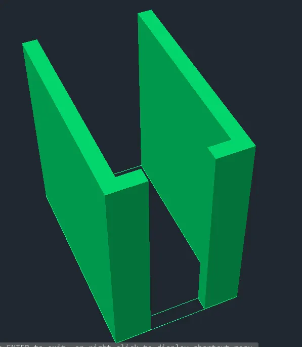
• Create a boundry region over the window lines
• Extrude the boundary to a height of 4’6”
• Draw a rectangle on top of the window opening using rectangle command
• Change the rectangle into a region
• Extrude the region to distance of 1’3” to below and then window openin is created as shown in figure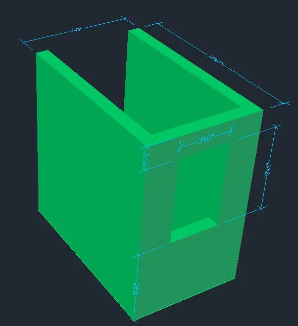
Step 4: Creating Elevation Windows
4’ Wide Window
Change the current layer to 3D_Window_Frame
Type UCS and click on face and select the face having 3’ wide window
• Draw a rectangle of dimension @3’,4’
• Offset the rectangle to inside to distnce of 2”
• Offset the offset rectangle to inside to distnce of 3”
• Draw center line connecting midpoints
• Offset the lines to both sides to a distance of 3”
• Trim all the unnecessary edges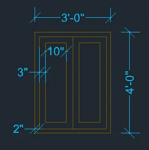
Start the boundary command and click on pick points
• Click inside the window frame area and press enter
Start SUBTRACT command
• Select the bigger region and then select the smaller regions to subtarct them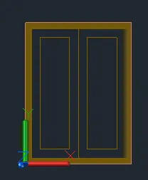
Change the current layer to 3D_Window_Mulion
Start the boundary command and click on pick points
• Click inside the window Mulion area and press enter
Start SUBTRACT command
• Select the bigger region and then select the smaller glass region to subtarct it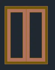
Change the current layer to 3D_Window_Glass
Start the boundary command and click on pick points
• Click inside the window glass area and press enter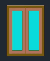
All the layers are extruded to give window projection look as shown in figure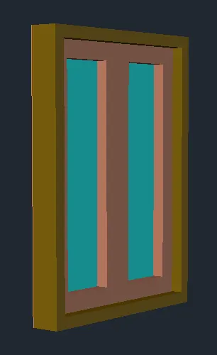
Step5: Creating Elevation View
The windows created in step 4 are placed at its positions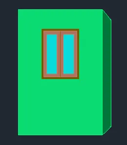
• Group all the items to create the elevation view
• Copy the block having 4’ height window and place it 3 times as shown in figure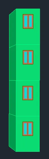
• Create the top part of the drawing using 4” wall with height 6’5” from top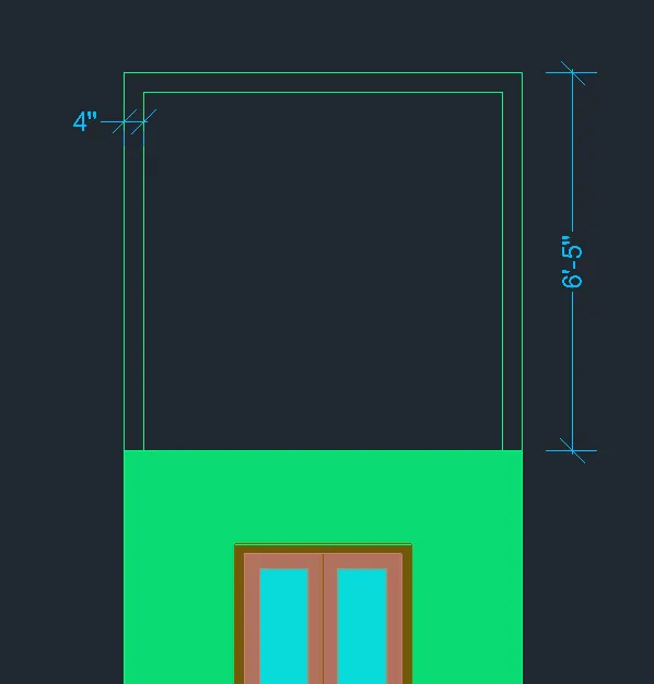
• Create a boundary for the wall
• Extrude the boundary to 9” as shown in elevation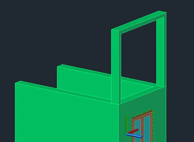
Step 6: Creating Views
Click on home button of the view cuble and zoom for better view
Go to visuvilise tab and click on new view
• Set view name as VIEW 1
• Click on current view and press ok
Click on the Front view of the view cube and zoom for better view
Go to visuvilise tab and click on new view
• Set view name as VIEW 2
• Click on current view and press ok
Click on the Top view of the view cube and zoom for better view
Go to visuvilise tab and click on new view
• Set view name as VIEW 3
• Click on current view and press ok
Result:
Initially all the layers necessary are created with respective line types and line weights. Then plan view is drawn as shown in step 2. Then from step 3 the 3D view is created with respective layers assigned. The UCS view is changed accordingly to make changes to the 3D view and 3D dimensions.Boundary command is used for creating regions along the boundaries and extruding them. After this views are created for showing result.The result consists of different views of the 3D model such as top view(View 3), SW isometric(View 1), NE isometric(View 2), Windows.
• All dimensions are in Feet and Inches
• Text and dimensions are added with respective layers
1. View 1(SW isometric)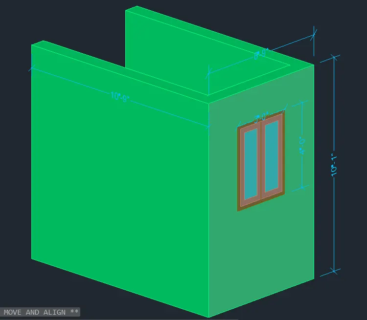
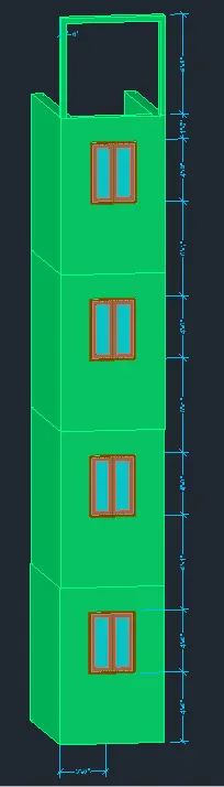
2. View 2(Front View)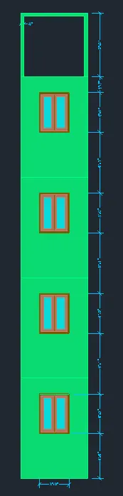
3.View 3(top view)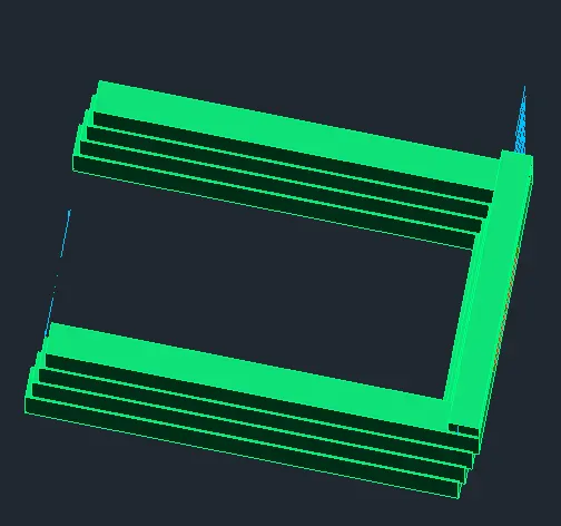
4. Windows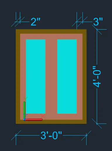
3. Create the ismoteric 3d view of a stair with railing as shown in the plan and elevation. Assume the size of the balustrades and the hand rails.
Aim: To draw the 3D view of a stair with railing as shown in the plan and elevation
Introduction:
A plan view and elevation view of stair case are given and they are to be converted into a 3D model. Plan view consists of number of stairs in the staircase and their horizontal dimensions of stair case. Elevation view consists of staircase side view and vertical dimensions of staircase and stair case components such height of hand rails and their spacing in the landing. Thickness of stair slab is given as the box Some other components of the stair re told to be assumed. The assume dimensions are as follows
• Dimension of vertical rails is 1” diameter
• Dimensions of hand rails is 2” diameter
Procedure:
Open AutoCAD
In Startup settings start from scratch select Imperial (Feet and Inches)
Open grid and snap settings
• Change snap and grid spacing to 1’
• Change major line every grid line to 10
• Turnoff adaptive grid
Type ‘un’ in command box and press enter
Change units’ type to decimal and precision to 1’1/16” and insertion scale to inches
Change the workspace setting of AutoCAD from ‘drafting and annotation’ to ‘3D Modeling’
Step 1: Creating Layers
Open Layer properties and create new layers by clicking on new layer or right click on any layer and select new layer to create new layer
Layers are created as follows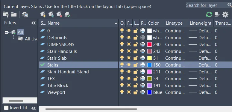
Step 2: Creating 2D Plan View of Staircase
Change the current layer to stairs
• Draw a rectangle of dimensions 3’X12’
• Explode the rectangle
• Offset the side edges to inside to a distance of 1”
• Offset the bottom edge to upside 9 times to a distance of 1’ as shown in figure
Step 3: Creating Side View
Change the view to 3d by clicking on home button of view cube and chance the view to right view
Set UCS as Right
• Start line command and draw a vertical line of length 6”
• Draw a horizontal line of length 1’
• Repeat the same process for 9 times to draw 9 steps
• After reaching 9 steps draw a landing of length of 3’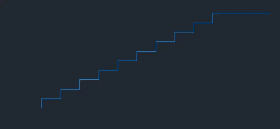
• Draw a line of 1’ at the bottom step
• Draw a line of 6” at the top right edge of landing
• Draw a line of 1’6” backwards
• Draw a slab joining the lines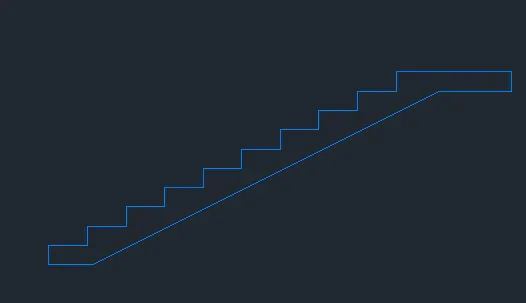
Step 4: Creating 3D View
Change the view to 3d by clicking on home button of view cube
Set UCS as world
Set the view style control as REALISTIC
• Create a region from the side view of the stairs
• Extrude the side view to a distacne of 3’ as shown in figure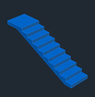
Hand Rails
Change the current layer to Stair_handrails
• Draw circle of diameter 1” with 2” offset from the top right edges of the first thread of staircase
• Change the circle into a region
• Extrude the region to a height of 3’ as shown in the figure
Change the current layer to Stair_handrails_Stand
• Draw a handrail stand at the bottom with dimension 2” and extrude as shown in figure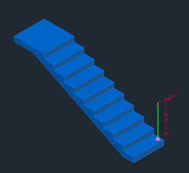
• Using copy command copy all the hand rail components on all stairs with same offset as shown in figure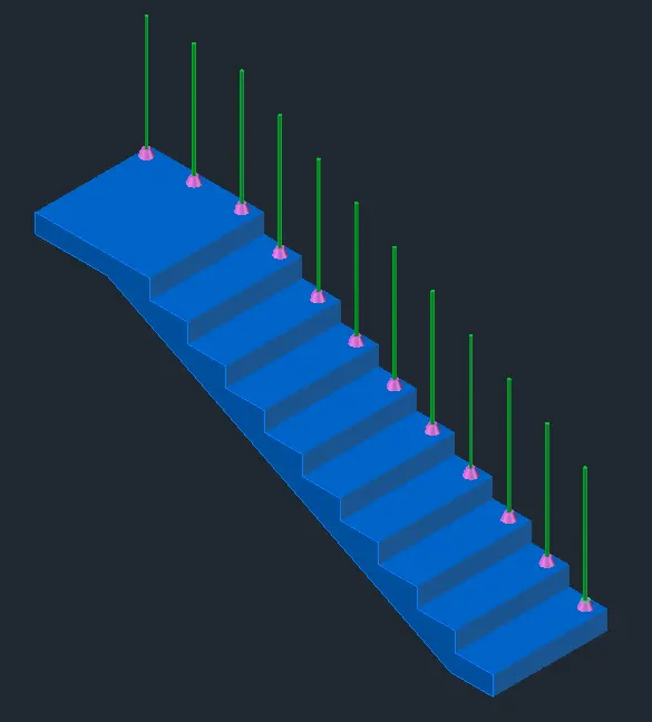
• Copy the same to the other side as shown in figure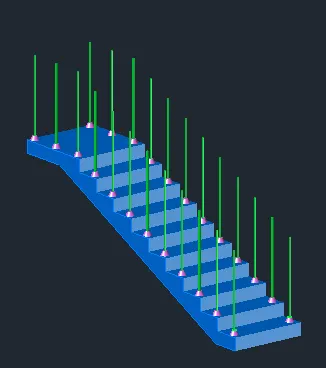
Change the current layer to Stair_handrails
• Draw a polyline connecting all the top edges of hand rails
• Change the UCS to front
• Draw a circle of diameter 2” on top of the first hand rail
• Create a region of the circle drawn
Start Sweep command
• Select the circle as object to sweep
• Select the poly line drawn as path of sweep as shown in figure
• Copy the same to the other side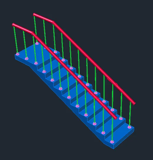
Step 5: Creating Views
Click on the Top view of the view cube and zoom for better view
Go to visuvilise tab and click on new view
• Set view name as VIEW 1
• Click on current view and press ok
Click on the Right view of the view cube and zoom for better view
Go to visuvilise tab and click on new view
• Set view name as VIEW 2
• Click on current view and press ok
Click on home button of the view cuble and zoom for better view
Go to visuvilise tab and click on new view
• Set view name as VIEW 3
• Click on current view and press ok
Click on the Front view of the view cube and zoom for better view
Go to visuvilise tab and click on new view
• Set view name as VIEW 4
• Click on current view and press ok
Result:
Initially all the layers necessary are created with respective line types and line weights. Then plan view and side elevation view are drawn as shown in step 2 and 3 respectively. Then in step 4the 3D view is created with respective layers assigned. The UCS view is changed accordingly to make changes to the 3D view and 3D dimensions.Boundary command is used for creating regions along the boundaries and extruding them. After this views are created for showing result.The result consists of different views of the 3D model such as top view(View 1), SW isometric(View 3), Side View(View 2), Front View(View 4).
• All dimensions are in Feet and Inches
• Text and dimensions are added with respective layers
1. View 1 (top view)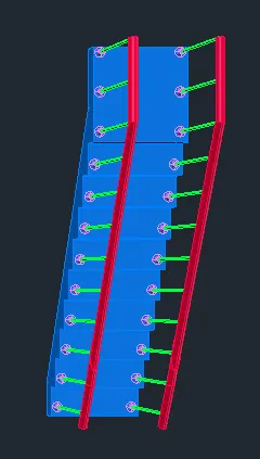
2. View 2 (Right Side View)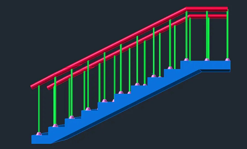
3. View 3(SW isometric)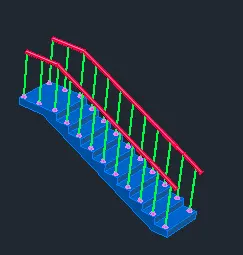
4. View 4(Front View)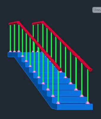
4. Create the 3D view of a Wall with spread footing . Create the Door opening only. Assume the size of the parpaet and the coping. See the plans and elevation for the details. Also, create a rendered view of the model with materials as of your choice.
Aim: To draw the 3D view of a Wall with spread footing as shown in the plan and elevation
Introduction:
A plan view and elevation view of a wall with spread footing under it are given and they are to be converted into a 3D model. Spread footing is a type of footing which goes all along the length of the wall in a building. It is used as shallow footing type. Plan view consists of horizontal dimensions of footing and the wall. Elevation view consists of vertical dimensions of different levels of footing, height of 230mm thickness wall. Some other components of the footing are told to be assumed. The assume dimensions are as follows
• Thickness of wall is assumed as 230mm
• Thickness of level 1 of footing is same as wall thickness i.e., 230mm.
• Coping Thickness of level 2 is offset of 50mm than the thickness of wall
• Thickness of level 3 is offset of 50mm than the thickness of level 2
• Thickness of level 4 is offset of 120mm than the thickness of level 3
Procedure:
Open AutoCAD
In Startup settings start from scratch select Metric (Meters and mm)
Open grid and snap settings
• Change snap and grid spacing to 100
• Change major line every grid line to 10
• Turnoff adaptive grid
Type ‘un’ in command box and press enter
Change units’ type to decimal and precision to 0.00 and insertion scale to inches
Change the workspace setting of AutoCAD from ‘drafting and annotation’ to ‘3D Modeling’
Step 1: Creating Layers
Open Layer properties and create new layers by clicking on new layer or right click on any layer and select new layer to create new layer
Layers are created as follows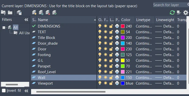
Step 2: Creating 2D Plan View of wall with spread footing
Change the current layer to wall
• Draw a rectangle of dimensions 670X7500
• Offset the rectangle to inside to a distance of 120mm
• Offset the offset rectangle inside to distance of 50mm twice.
• Explode all the offset rectangle
• Delete the top and bottom edges of the exploded rectangles
• Extend all the rectangle to top and bottom edges of outer rectangle.
• At the end select the individual lines and change their layers respectively
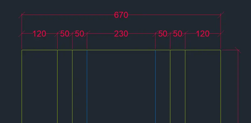
Creating Door Block
• Draw a rectabgle of dimenson 50X100mm
• Draw another rectangle with dimensions of 50X50mm
• Draw a line of length 850mm from the edge
• Draw an arc line of the door swing
• Convert the door into block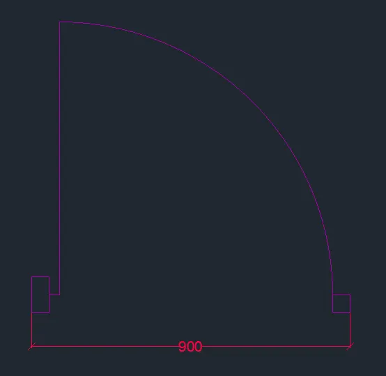
• Edit the block and add flip parameters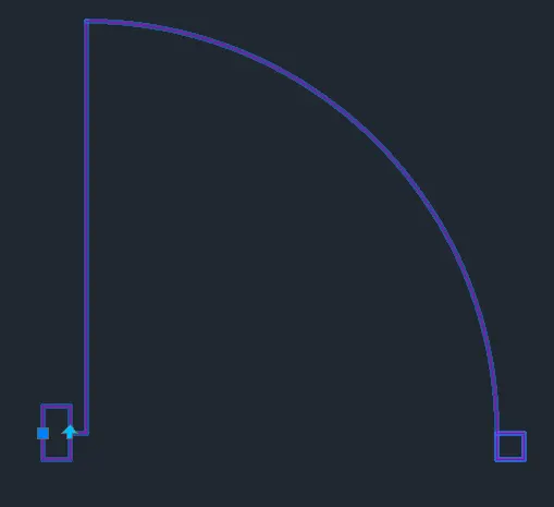
• Create the door opening of 900mm at the middle
• Add the door block by rotating the door
• Add the door shade using respective layer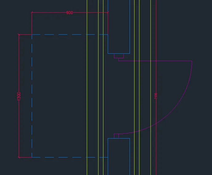
Step 3: Creating Elevaton view
Click on the Front view of the view cube and zoom for better view
Change the ucs to front
Change the current layer to G.L.
• Draw a line of certal length
• Offset the line to bottom 25mm
• Offset the last offset line bottom to distance of 150mm
Change the current layer to Wall
• Draw a rectangle of dimension 230X 3300 from the top left edge of Ground level
Change the current layer to roof level
• Draw roof of thickness 150mm as shown in figure
• Draw a Parapet wall of height 600mm as shown in figure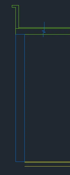
Footing Layers
• Draw a rectangle of dimension 230X600, below the floor level as shown in figure
• Draw a rectangle of dimension 330X400, below the first level as shown in figure
• Draw a rectangle of dimension 430X400, below the second level as shown in figure
Change the current layer to Footing
• Draw a rectangle of dimension 670X300, below the third level as shown in figure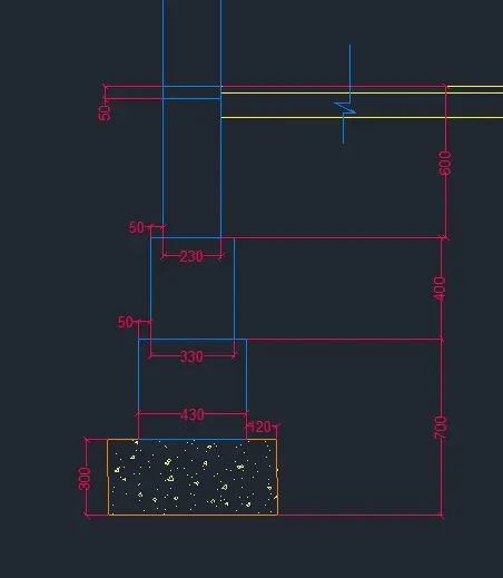
Trim the unnecessary edges
Door
Change the current layer to door
• Draw a line along the length of the door of 230mm at the ground level
• Offset the line to below to distance of 50mm below the ground level
• Offset the line to distance of 2100 to above
Change the current layer to Door Shade
• Draw the door shade as shown in figure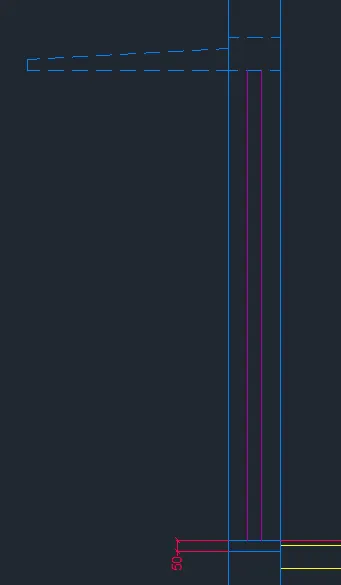
The end result of this step is as follows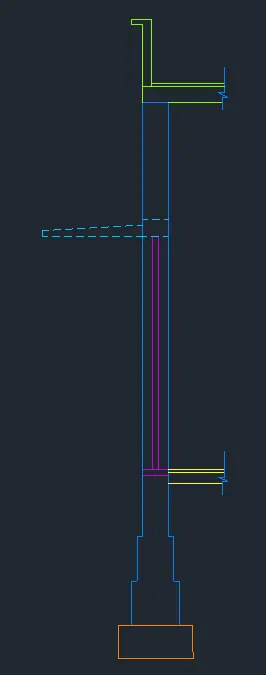
Step 4: Drawing 3D View of section
• For creating the 3D view initially boundaries are created
• Each boundary is created with its respective layer as current layer as shown in the following figure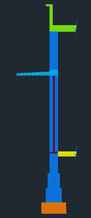
Extruding
• The created boundaries are to be extruded to a distance eof 7500mm
• Select the boundaries by changing their respective current layer
• Door opening is added by drawing a rectangle at the door locaton from the plan view
• Then from the extruded part the door region is subtracted from the wall using SUBTRACT command
• Similarly door shade is created with the opening above
• After door shade remaining layer is extruded as shown in figure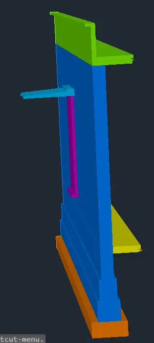
Step 6: Rendering
Rendering is done by adding materials the 3D view
• Material Browser is used for adding materials to objects
• The materials added for the comonents from the material browser are shown below
• Box mapping is done to adjust the texture of the wall
Lights
• Torch light is placed infront of the door at certail distance with fall off angle as 50 and Hotspot angle as 80 as shown in figure
• Distant light is also used
Step 7: Creating Views
Click on the Top view of the view cube and zoom for better view
Go to visuvilise tab and click on new view
• Set view name as VIEW 1
• Click on current view and press ok
Click on the Front view of the view cube and zoom for better view
Go to visuvilise tab and click on new view
• Set view name as VIEW 2
• Click on current view and press ok
Click on home button of the view cuble and zoom for better view
Go to visuvilise tab and click on new view
• Set view name as VIEW 3
• Click on current view and press ok
Click on home button of the view cuble and zoom for better view
Go to visuvilise tab and click on new view
• Set view name as VIEW 4
• Click on current view and press ok
Go to visuvilise and click on add camera
• Create a circle at required distance and turn it into a region
• Extrude the region to aheight of 1800mm
• Click on add camera
• Set name as cam 1
• Set intensity as 1500
• Set target such that entire wall section is visible
Result:
Initially all the layers necessary are created with respective line types and line weights. Then plan view and elevation view are drawn as shown in step 2 and 3 respectively. Then in step 4 the 3D view is created with respective layers assigned. The UCS view is changed accordingly to make changes to the 3D view and 3D dimensions.Boundary command is used for creating regions along the boundaries and extruding them. After extrusion and door area subraction is completed door is added and extruded. After 3D view completion Material Browser is used to add materials to the componets. Then rendering is checked with various materials for better view. Final rendering is done in step 6 including the creation of lights. Box Mapping is used to adjust the tiles and texture of render. After this views are created for showing result.The result consists of different views of the 3D model such as top view(View 1), SW isometric(View 3), Side View(View 2), Cam1 view(Front door View)
• All dimensions are in millimeters
• Text and dimensions are added with respective layers
1. View 1 (top view)
2. View 2 (Right Side View)
3. View 3(SW isometric)
4. Cam1 view(Front Door View)
5. Rendered View