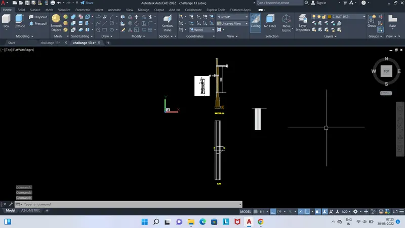
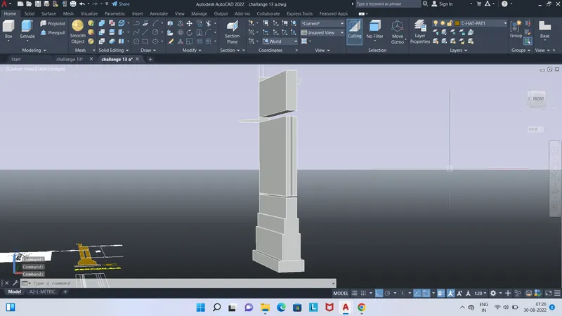
Creating 3D Isometric view of various structural elements in AutoCAD
Q.01 Create a 3D Isometric View of the building with plan and elevation given.
ANS:
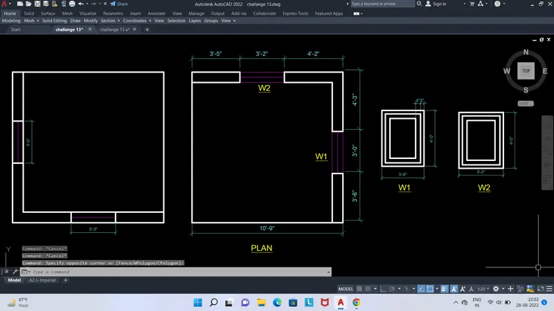
AIM:Modern 3D modeling provides a level of design depth that rough sketches or 2D designs cannot, such as improved control over details.
- It also lets engineers explore the physical aspects of a design without surrendering to physical limitations..
- NOW U CAN SEEN IT TOP VIEW IN SNAPSHOT.THIS IS TOP VIEW PLAN.
- U CAN SEEN IT BELOW SNAP SHOT
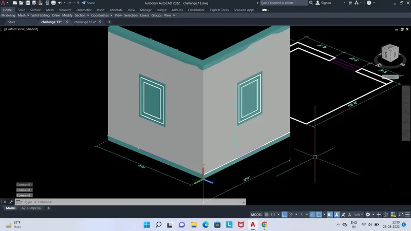
Q.02 Create the 3D View of the Building Façade as given in the plan and elevation. Also, see the detail of the window.
ANS:
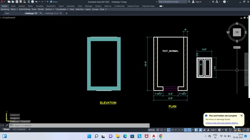
AIM :
- Draw an elevation line in the drawing.
- Select the elevation line.
- Click Building Elevation Line tab Modify panel Generate Elevation.
- Select the type of elevation object you want to create: ...
- For Style to Generate, select a style for a 2D elevation.
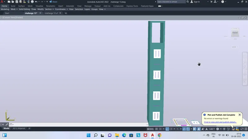
Q.03 Create the ismoteric 3d view of a stair with railing as shown in the plan and elevation. Assume the size of the balustrades and the hand rails.
ANS:
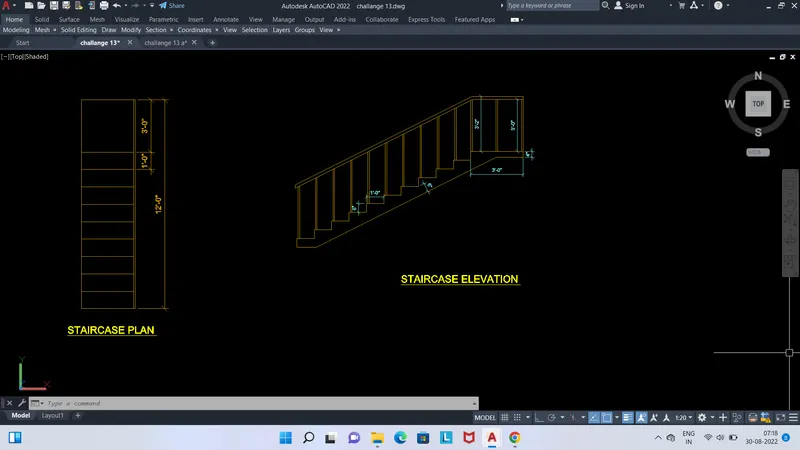
- Open the tool palette that you want to use, and select a stair tool. If necessary, scroll to display the tool that you want to use. ...
- Specify the insertion point of the stair. ...
- Specify the direction point of the stair. ...
- Continue adding stairs, and press Enter.
Q.04 Create the 3D view of a Wall with spread footing . Create the Door opening only. Assume the size of the parpaet and the coping. See the plans and elevation for the details. Also, create a rendered view of the model with materials as of your choice.
ANS: