Creating 3D Isometric view of various structural elements in AutoCAD
1. Create a 3D Isometric View of the building with plan and elevation given.
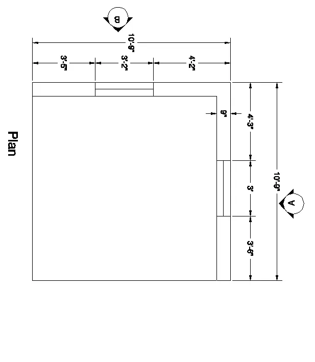
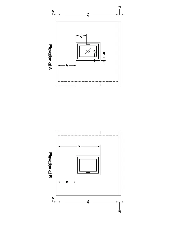
Answer:-
step1:- command a xl line and draw vertical line and again command xl line and draw a horizontal line, the two are trim negative directions and use offset with above daigram have dimensions and draw a residential plan.
step2:- command a circle tool used the door shape.
step3:- command a dimlinear and show the dimensions.
step4:- select the separted parts like walls (exterior, interior), doors , caboards, steps, are select individual and apply a different colour for each item.
step5:- command a table tool and select no rows and columns and draw a table.
step6:- command a line tool and draw a reinforcement.
step7:- command a text and enter all the text and save.
2. Create the 3D View of the Building Façade as given in the plan and elevation. Also, see the detail of the window.
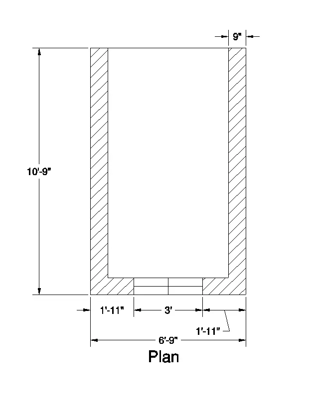
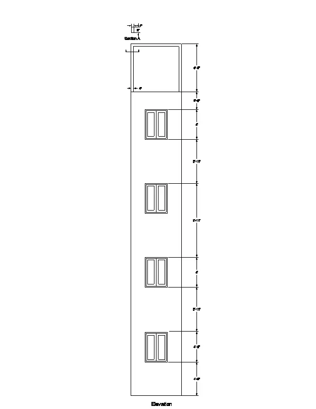
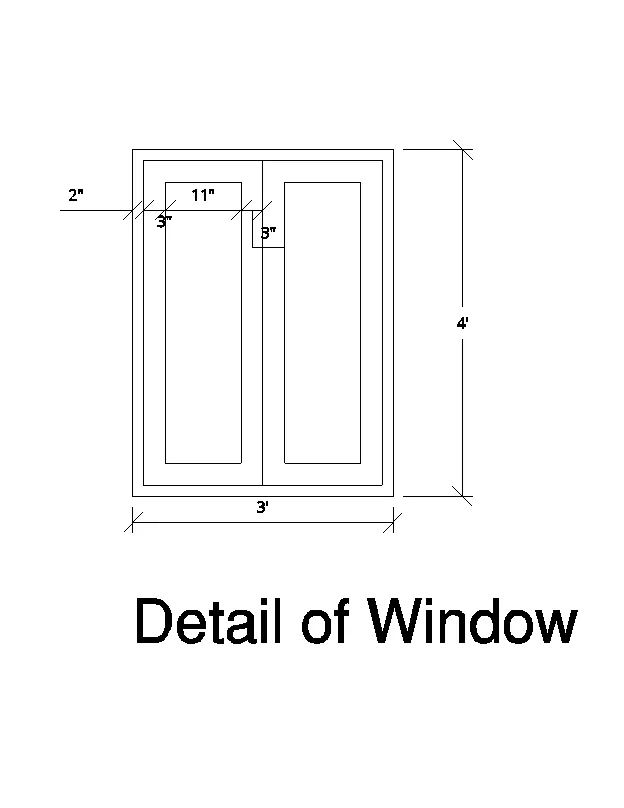
Answer:-
step1:- command a xl line and draw vertical line and again command xl line and draw a horizontal line, the two are trim negative directions and use offset with above daigram have dimensions and draw a residential plan.
step2:- command a circle tool used the door shape.
step3:- command a dimlinear and show the dimensions.
step4:- select the separted parts like walls (exterior, interior), doors , caboards, steps, are select individual and apply a different colour for each item.
step5:- command a table tool and select no rows and columns and draw a table.
step6:- command a line tool and draw a reinforcement.
step7:- command a text and enter all the text and save.
3. Create the ismoteric 3d view of a stair with railing as shown in the plan and elevation. Assume the size of the balustrades and the hand rails.
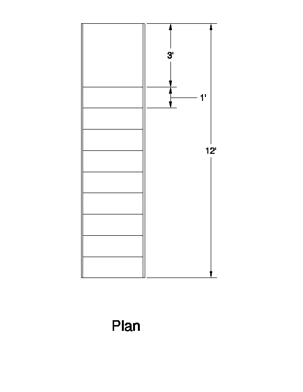
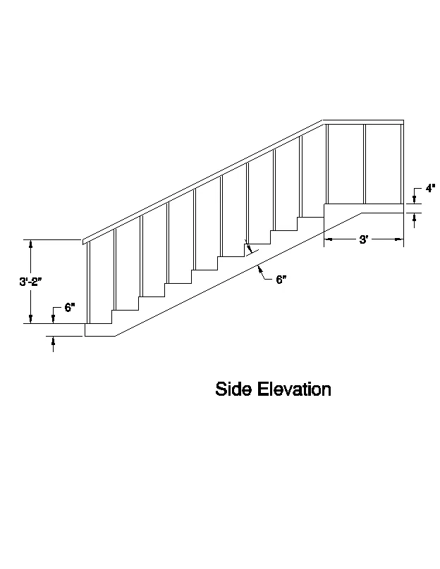
Answer:-
step1:- command a xl line and draw vertical line and again command xl line and draw a horizontal line, the two are trim negative directions and use offset with above daigram have dimensions and draw a residential plan.
step2:- command a circle tool used the door shape.
step3:- command a dimlinear and show the dimensions.
step4:- select the separted parts like walls (exterior, interior), doors , caboards, steps, are select individual and apply a different colour for each item.
step5:- command a table tool and select no rows and columns and draw a table.
step6:- command a line tool and draw a reinforcement.
step7:- command a text and enter all the text and save.
4. Create the 3D view of a Wall with spread footing . Create the Door opening only. Assume the size of the parpaet and the coping. See the plans and elevation for the details. Also, create a rendered view of the model with materials as of your choice.
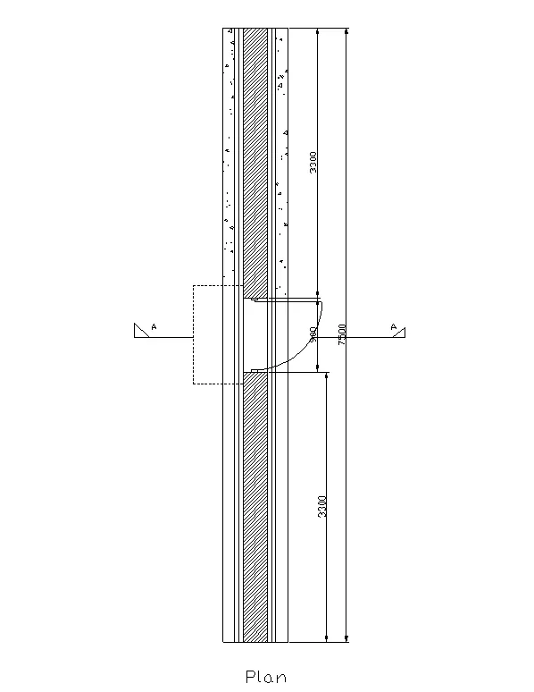
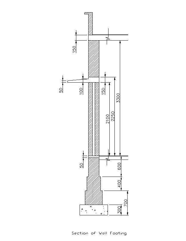
Answer:-
step1:- command a xl line and draw vertical line and again command xl line and draw a horizontal line, the two are trim negative directions and use offset with above daigram have dimensions and draw a residential plan.
step2:- command a circle tool used the door shape.
step3:- command a dimlinear and show the dimensions.
step4:- select the separted parts like walls (exterior, interior), doors , caboards, steps, are select individual and apply a different colour for each item.
step5:- command a table tool and select no rows and columns and draw a table.
step6:- command a line tool and draw a reinforcement.
step7:- command a text and enter all the text and save.