Creating 3D Isometric view of various structural elements in AutoCAD
COMMAND USED IN CHALLENGE
- LINE
- RECTANGLE
- TRIM
- COPY
- MOVE
- EXPLODE
- CIRCLE
- MIRROR
- LAYER
- HATCH
- FILLET
- JOIN
- DIMLINEAR
- DIMCONTINUE
- UCS
- 3D ORBIT
- 3D ROTATE
- BOUNDARY
- EXTRUDE
- REGION
- UNION
- SUBTARCT
- CAMERA
- BLOCK
- RENDER RR
- SWEEP
- CREATE LIGHT
AIM :- Create a 3D isometric view of the building with plan and elevation given.
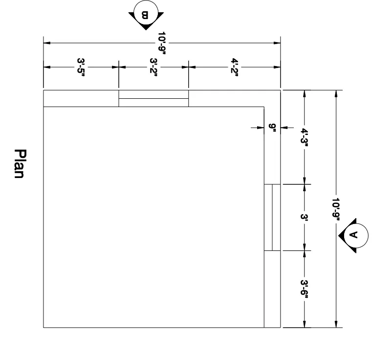
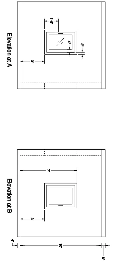
INTRODUCTION :- 3D isometric view of building with plan and elevation is created with the help of various tools in AutoCAD. All dimension of the drawing is taken same as given in plan & section. The height of wall is 10’ and the window size are same as given in challenge figure. The wall thickness is 9” as given.
PROCEDURE :-
STEP 01.
- Go to START MENU select AutoCAD
- In Command prompt type STARTUP then enter
- Enter new value of startup as 1
- Go to application menu and select NEW
- Select IMPERIAL, then ok
- Type UNIT command
- In drawing unit dialog box select ENGINEERING
- In precision select 0’-0”
- INCHES in insertion scale then ok
- Select 3D Modelling from the workplace
- Set limits by entering LIMIT command
- Lower-left corner 0’0”,0’0” and upper-right corner 100’,100’
STEP 02.
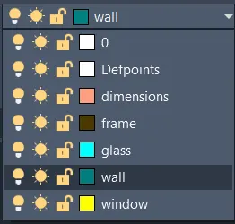
CREATING LAYER
- Create layers by clicking on ribbon tab to layer properties
- Then select the new layers according to your preference
- Layer created as follow shown
STEP 03.
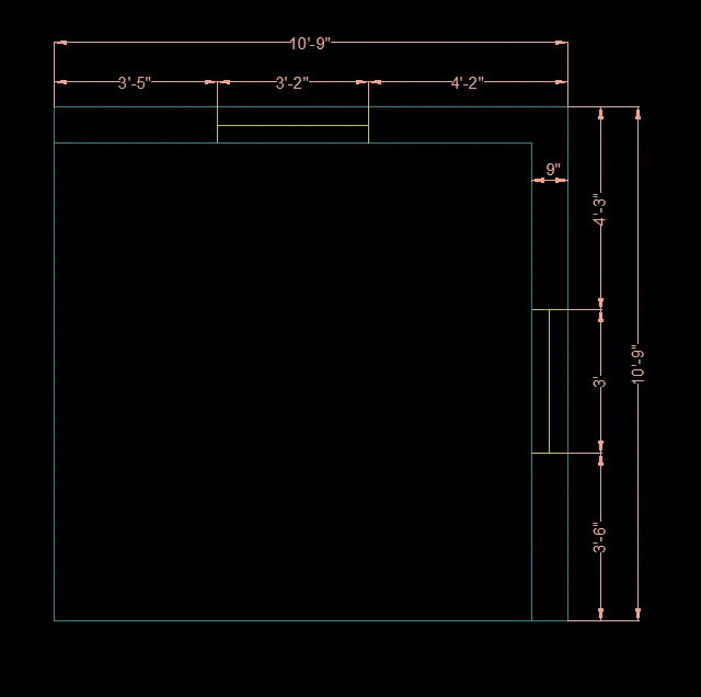
2D VIEW OF PLAN
- Type LINE in command prompt
- Specify first point : 0,0
- Specify next point : 10’9” enter ( X-axis)
- Specify next point : 10’9” enter (Y-axis)
- Specify next point : 10’9” enter (- X-axis)
- Specify next point : 10’9” enter (- Y-axis)
- Type OFFSET in command prompt
- Offset distance : 9” enter
- Select object select (X&Y axis) line
- Then offset it to inner side
- Now make windows by using LINE command as respective size
- Now use DIMLINEAR command for dimensions
3D VIEW OF PLAN
- Change the view to 3D by clicking on home of view cube
- Create boundaries for the wall by using BO command
- Now use EXTRUDE command to extrude the wall to 10’10”
- Now use RECTANGLE command to draw rectangle at window section at top & bottom respectively
- Now use BO command to make them boundaries
- EXTRUDE the bottom & top of section-A at hight of 3’ respectively
- Now EXTRUDE the bottom & top of section-B at hight of 3’ respectively
- Now use UNION command to make all of them to same wall
- UCS is changed preferably according to drawing situations
WINDOWS CREATION
ELEVATION A
- IN TOP VIEW
- RECTANGLE in command prompt
- Specify first corner : 0,0
- Specify other corner : @3’2”,4’ enter
- OFFSET in command prompt
- 1st OFFSET to 3”
- 2nd OFFSET to 4”
- IN 3D VIEW
- Change the view to 3D by clicking on home of view cube
- Change there layers accordingly from LAYER
- Now EXTRUDE the frame to 9” & mullein to 4” & glass to 3”
- COPY command and make 3 copy separately
- SUBTRACT command and make 1st object to frame
- 2nd object to mullein & 3rd object to glass
- Now use MOVE command and put one by one in frame
- Now window is completed
- Again by using MOVE command put that window in section-A side
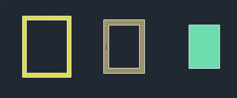
ELEVATION B
- IN TOP VIEW
- RECTANGLE in command prompt
- Specify first corner : 0,0
- Specify other corner : @3’,4’ enter
- OFFSET in command prompt
- 1st OFFSET to 3”
- 2nd OFFSET to 4”
- IN 3D VIEW
- Change the view to 3D by clicking on home of view cube
- Change there layers accordingly from LAYER
- Now EXTRUDE the frame to 9” & mullein to 4” & glass to 3”
- COPY command and make 3 copy separately
- SUBTRACT command and make 1st object to frame
- 2nd object to mullein & 3rd object to glass
- Now use MOVE command and put one by one in frame
- Now window is completed
- Again by using MOVE command put that window in section-B side
RESULT :-
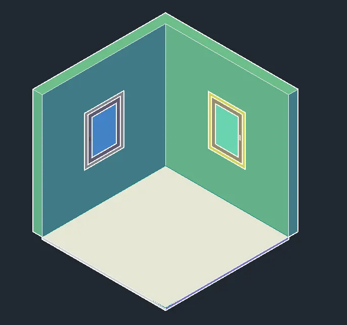

- All dimensions are in feet & inches as shown in figure.
- Created a 3D view of building plan as given plan section-A & section-B of the building.
- Drawing is completed by using various tools and command in AutoCAD
- The procedure of the drawing is shown in procedure in step by step.
AIM :- Create a 3D view of the building façade as given in the plan and elevation.
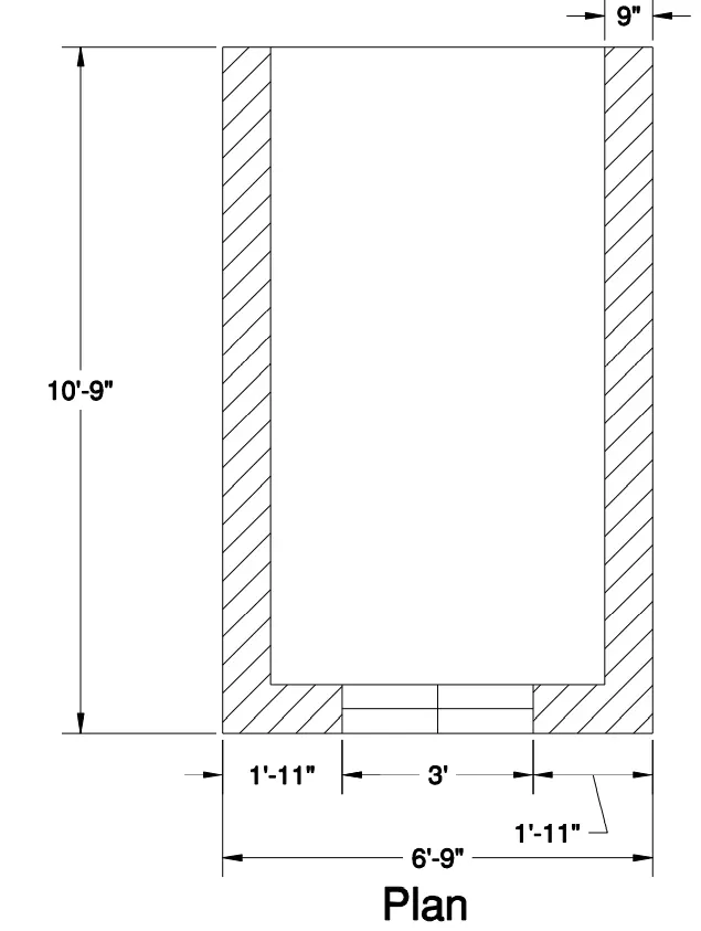
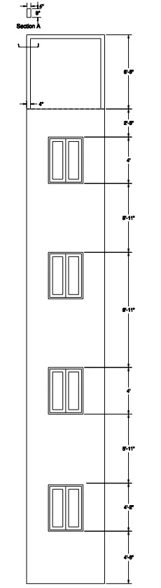
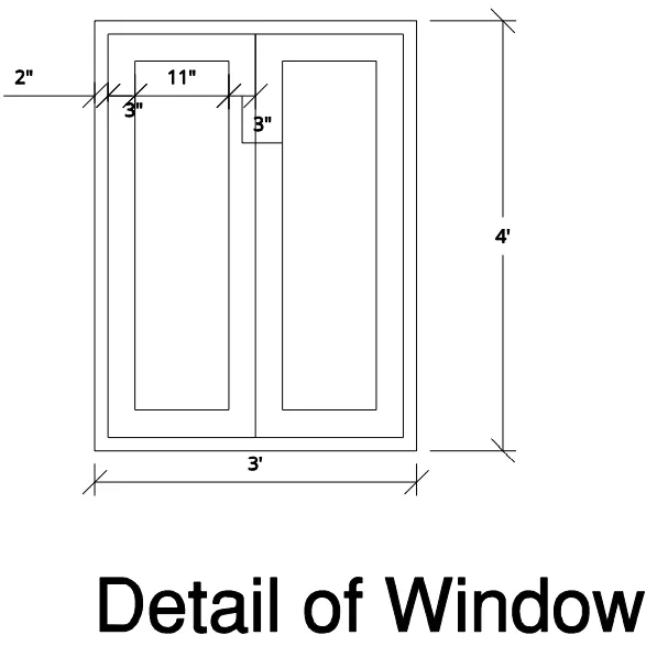
INTRODUCTION :- 3D isometric view of building with plan and elevation is created with the help of various tools in AutoCAD. All dimension of the drawing is taken same as given in plan & section. The height of wall is 10’9” and the window size are same as given in challenge figure. The wall thickness is 9” as given.
PROCEDURE :-
STEP 01.
- Go to START MENU select AutoCAD
- In Command prompt type STARTUP then enter
- Enter new value of startup as 1
- Go to application menu and select NEW
- Select IMPERIAL, then ok
- Type UNIT command
- In drawing unit dialog box select ENGINEERING
- In precision select 0’-0”
- INCHES in insertion scale then ok
- Select 3D Modelling from the workplace
- Set limits by entering LIMIT command
- Lower-left corner 0’0”,0’0” and upper-right corner 100’,100’
STEP 02.
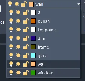
CREATING LAYER
- Create layers by clicking on ribbon tab to layer properties
- Then select the new layers according to your preference
- Layer created as follow shown
STEP 03.
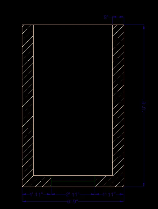
2D VIEW OF PLAN
- Type LINE in command prompt
- Specify first point : 0,0
- Specify next point : 10’9” (-Y-axis)
- Specify next point : 6’9” (X-axis)
- Specify next point : 10’9” (Y-axis)
- Specify next point : Close enter
- OFFSET in command prompt
- Offset distance : 9” enter
- Select object select (X&Y axis) line
- Then offset it to inner side
- Now make windows by using LINE command as respective size
- Now use DIMLINEAR command for dimensions
3D VIEW OF PLAN
- Change the view to 3D by clicking on home of view cube
- Create boundaries for the wall by using BO command
- Now use EXTRUDE command to extrude the wall to 10’9”
- Now use RECTANGLE command to draw rectangle at window section at top & bottom respectively
- Now use BO command to make them boundaries
- EXTRUDE the bottom at hight of 4’6”
- Now EXTRUDE the top at hight of 2’3”
- Now use UNION command to make all of them to same wall
- UCS is changed preferably according to drawing situations
WINDOWS CREATION
ELEVATION
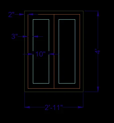
- IN TOP VIEW
- RECTANGLE in command prompt
- Specify first corner : 0,0
- Specify other corner : @3’,4’ enter
- OFFSET in command prompt
- 1st OFFSET to 3”
- Now EXPLODE the rectangle
- LINE command & draw line from mid of rectangle
- Now OFFSET to 3” for the glass of window
- IN 3D VIEW
- Change the view to 3D by clicking on home of view cube
- Change there layers accordingly from LAYER
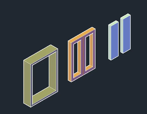
- Now EXTRUDE the frame to 9” & mullein to 4” & glass to 3”
- COPY command and make 3 copy separately
- SUBTRACT command and make 1st object to frame
- 2nd object to mullein & 3rd object to glass
- Now use MOVE command and put one by one in frame
- Now window is completed
- Again by using MOVE command put that window in the respective space
- Now use the COPY command for making three storey of building
- Again use LINE command to draw the boundary of the wall
- And OFFSET used as 4”
- Then EXTRUDE to 9” as shown in figure
- Again by using MOVE command place at the respective space
RESULT :-
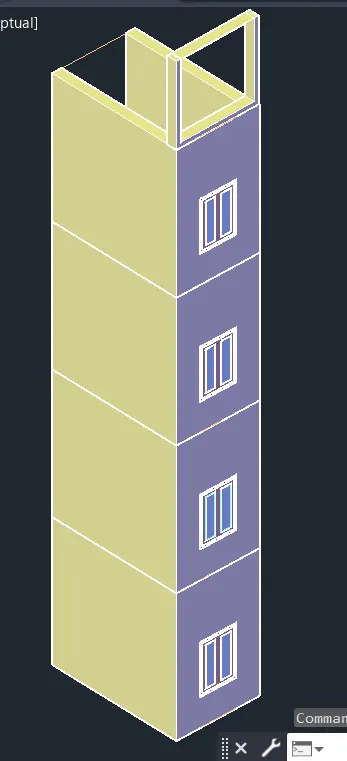
- All dimensions are in feet & inches as shown in figure.
- Created a 3D view of building plan as given plan of the building.
- Drawing is completed by using various tools and command in AutoCAD.
- The procedure of drawing is shown each step.
AIM :- Create a isometric view 3D view of stair with railing as shown in plan and elevation.
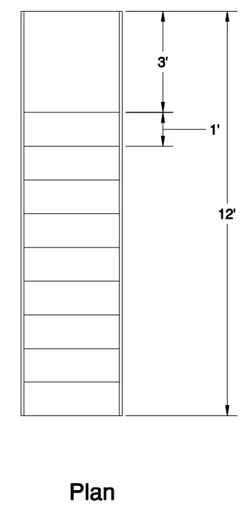
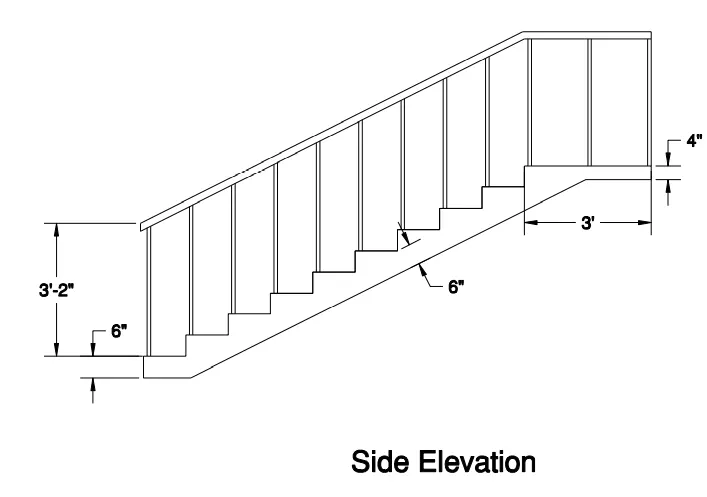
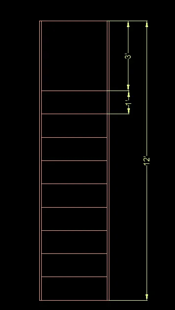
INTRODUCTION :- 3D isometric view of stair with railing is drawn with help given dimensions in figure. In stairs it have tread of 1’ and riser 6” and the width of stairs is 3’ as given and the total length of the stair is 12’. The balustrades and the hand rails are having 2” diameter cylindrical shape and the height of balustrades is 3’.
PROCEDURE :-
STEP 01.
- Go to START MENU select AutoCAD
- In Command prompt type STARTUP then enter
- Enter new value of startup as 1
- Go to application menu and select NEW
- Select IMPERIAL, then ok
- Type UNIT command
- In drawing unit dialog box select ENGINEERING
- In precision select 0’-0”
- INCHES in insertion scale then ok
- Select 3D Modelling from the workplace
- Set limits by entering LIMIT command
- Lower-left corner 0’0”,0’0” and upper-right corner 100’,100’
STEP 02.
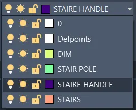
CREATING LAYER
- Create layers by clicking on ribbon tab to layer properties
- Then select the new layers according to your preference
- Layer created as follow shown
STEP 03.
2D VIEW OF STAIRS
- Type LINE in command prompt
- Specify first point : 0,0
- Specify next point : 12’ (-Y-axis)
- Specify next point : 3’ ( X-axis)
- Specify next point : 12’ (Y-axis)
- Specify next point : Close the command
- OFFSET in command prompt
- OFFSET from left & right to 2” inner side
- OFFSET again for stairs at distance of 1’
- TRIM command to trim unwanted lines
- DIMLINEAR command for dimensions
3D VIEW OF STAIRS
- Change the view to 3D by clicking on home of view cube
- Change there layers accordingly from LAYER
- JOIN command to join the lines
- Now BO command to make it as boundary
- Now EXTRUDE command
- Then EXTRUDE it to 3’
- Now by using CIRCLE command create a circle of 2” diameter
- Now OFFSET to 2” from the corner of the bottom step
- Now by using MOVE command put that circle at the 1st step
- Now COPY to other side at same distance from that side also
- Again COPY the both circle of step 1
- And COPY at same distance to all other steps of stairs
- EXTRUDE the circle for look like as balustrades
- Now draw a LINE from bottom cylindrical balustrade to top of balustrade
- Now use the JOIN command to make it single LINE
- Now draw a CIRCLE of 2” diameter
- Now use SWEEP command
- And sweep it to railing line
- COPY the same to other side also
RESULT :-
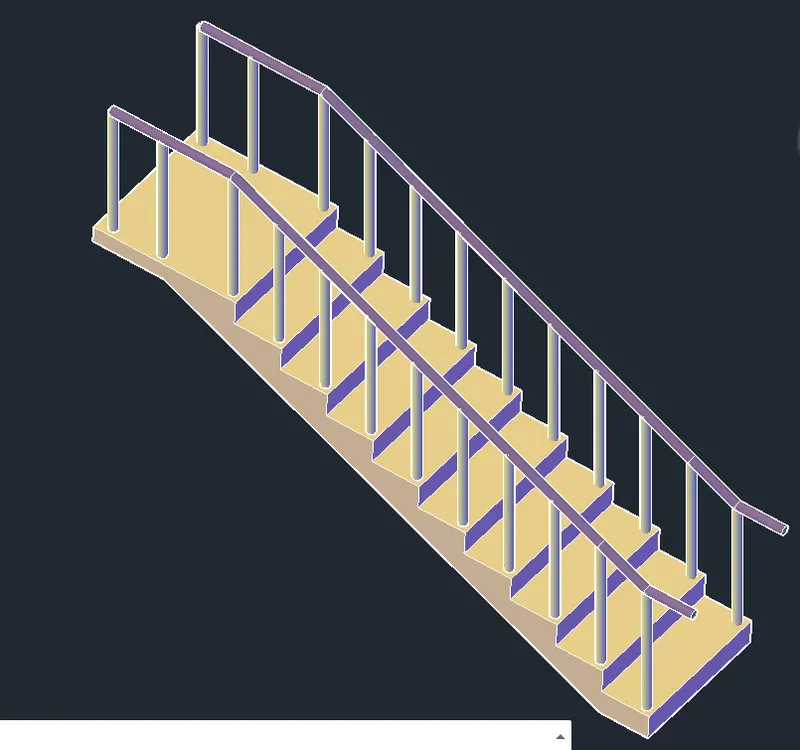
- All dimensions are in feet & inches as shown in figure.
- Created a 3D view of stairs as the given plan.
- Drawing is completed by using various tools and command in AutoCAD.
- The procedure of drawing is shown each step.
AIM :- Create a 3D view of a wall with spread footing. Create the door opening only. By assuming the size of parapet and cooping. Use the plan and elevation for the details. Also create a render view of the model with materials as of own choice.
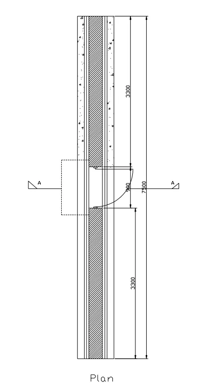
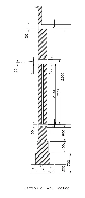
INTRODUCTION :- 3D isometric view of a wall spread footing. Doors parapet and cooping are drawn as shown in figure. By using the given plan size accordingly. Dimensions are used as decimal for the drawing and the height of wall is 7500 & door size is 900 & 2100 and other remaining size are assumed by own.
PROCEDURE :-
STEP 01.
- Go to START MENU select AutoCAD
- In Command prompt type STARTUP then enter
- Enter new value of startup as 1
- Go to application menu and select NEW
- Select IMPERIAL, then ok
- Type UNIT command
- In drawing unit dialog box select DECIMAL
- In precision select 0-0
- MILIMETER in insertion scale then ok
- Select 3D Modelling from the workplace
- Set limits by entering LIMIT command
- Lower-left corner 0,0 and upper-right corner 100,100
STEP 02.
CREATING LAYER
- Create layers by clicking on ribbon tab to layer properties
- Then select the new layers according to your preference
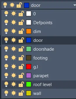
- Layer created as follow shown
STEP 03.
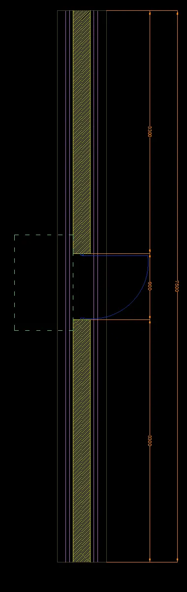
2D VIEW OF PLAN
- Type LINE in command prompt
- Specify first point : 0,0
- Specify next point : 7500 (Y-axis)
- Specify next point : 670 (-X-axis)
- Specify next point : 7500 (-Y-axis)
- Specify next point : Close command
- OFFSET in command prompt
- OFFSET left & right line to distance of 120 to inner side
- OFFSET last offset line to distance of 50 in inner side
- Again OFFSET to 50 last line to inner side
- Now again OFFSET bottom & top to distance of 3300
- Now draw TRIM other line of offset
- At the mid of LINE command draw block for door both side
- LINE to door section some hight
- ARC command for door panel
- HATCH command used for hatching
- TRIM command to trim unwanted lines
- DIMLINEAR command for dimensions
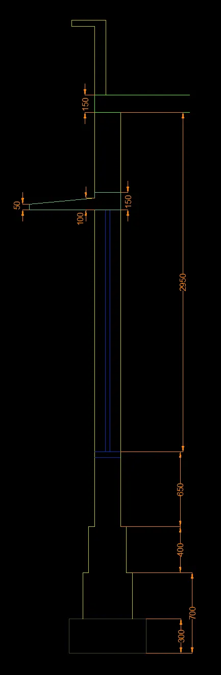
2D VIEW OF SECTION OF WALL FOOTING
- RECTANGLE in command prompt
- Specify first corner : click anywhere
- Specify other corner : @670,300 enter
- LINE in command prompt
- Specify first point : corner of rectangle
- Specify next point : 120 (-X-axis)
- Specify next point : 400 (Y-axis)
- Specify next point : 430 (-X-axis)
- Specify next point : 400 (-Y-axis)
- TRIM in command prompt
- Trim that line which started reference from rectangle
- LINE in command prompt
- Specify first point : click top of last shape
- Specify next point : 50 (-X-axis)
- Specify next point : 400 (Y-axis)
- Specify next point : 330 (-X-axis)
- Specify next point : 400 (-Y-axis)
- TRIM in command prompt
- Trim that line which started reference from rectangle
- LINE in command prompt
- Specify first point : click top of last shape
- Specify next point : 50 (-X-axis)
- Specify next point : 400 (Y-axis)
- Specify next point : 230 (-X-axis)
- Specify next point : 400 (-Y-axis)
- TRIM in command prompt
- Trim that line which started reference from rectangle
- LINE in command prompt
- Specify first point : click top of last shape
- Specify next point : 50 (-X-axis)
- Specify next point : 600 (Y-axis)
- Specify next point : 230 (-X-axis)
- Specify next point : 600 (-Y-axis)
- TRIM in command prompt
- Trim that line which started reference from rectangle
- LINE in command prompt
- Specify first point : select top of last line
- Specify next point : 3300 (Y-axis)
- Specify next point : 230 (-X-axis)
- Specify next point : 3300 (-Y-axis)
- LINE command is used to draw door section with the respective size given
- Also LINE command used to draw chajja section with respective size given
- HATCH command used to provide hatch
- TRIM command to trim unwanted lines
- DIMLINEAR command for dimensions
3D VIEW OF FOOTING & PLAN
- Change the view to 3D by clicking on home of view cube
- Change there layers accordingly from LAYER
- Use BO command to create boundary
- EXTRUDE in command prompt
- Now extrude then to hight of 7500 separately each boundary
- Door opening is crated separately then EXTRUDE it to then use
- Use MOVE command and place it to the door section
- Door shade is created by making RECTANGLE
- Now EXTRUDE it
- Now use MOVE command and place it to the section of door
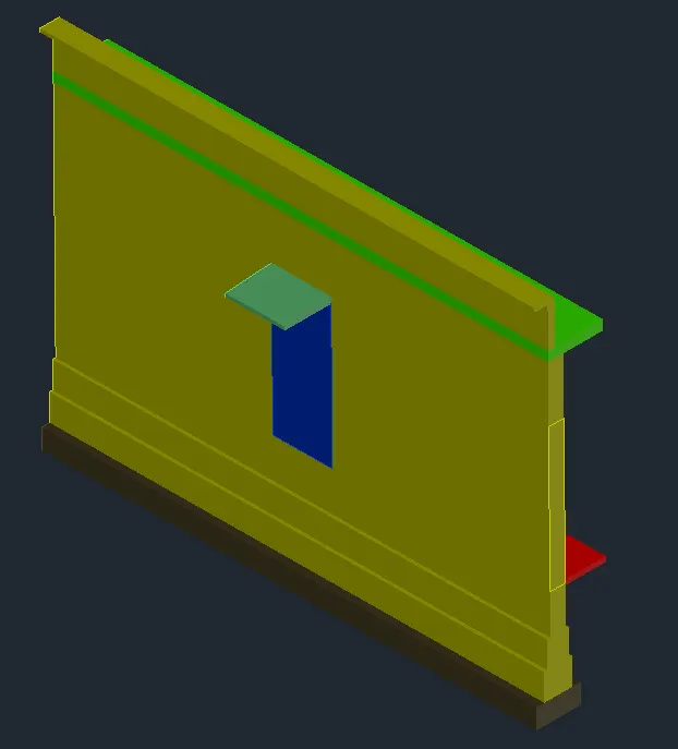
RENDERING
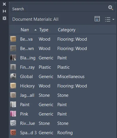
- Select material browser from ribbon
- The material added for component is show below
- Box mapping is done to adjust the texture of the wall
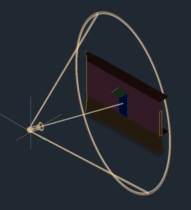
LIGHTS
- Select from the ribbon
- Spot light is placed in front of door at certain distance
- With fall of angle as 50 and hotspot angle as 80
- Distance of light is used to mange the spot light torch
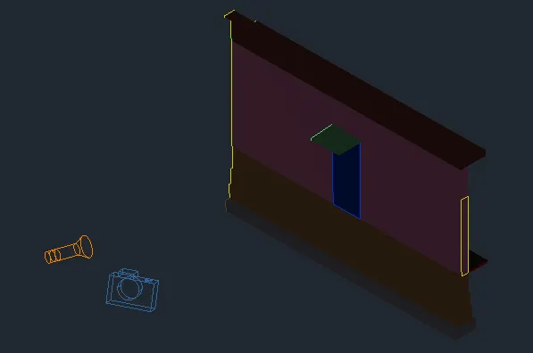
CAMERA
- Select camera from ribbon
- And place it accordingly view direction
- Now watch the view and adjust the camera accordingly
- View comes clear then enter
NOW FOR RENDERING VIEW
- Type RENDER in command prompt
- I was unable to show rendered image cause I have cracked version of AutoCAD.
RESULT :-
- Created a 3D view of plan and elevation of footing by using AutoCAD.
- All dimensions are in millimetres as shown in figure.
- All step are shown in procedure section and each have separate image of drawing.
- Drawing completed by using various tools & command in AutoCAD.
NOTE :- I HAVE CRACKED VERSION OF AutoCAD THATS WHY I'M UNABLE TO PRESENT THE ACTUAL RENDERED VIEW OF THE PLAN.