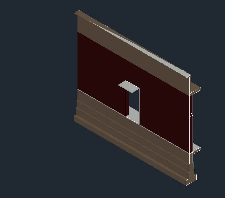
Creating 3D Isometric view of various structural elements in AutoCAD
Question 1. Create a 3D Isometric View of the building with plan and elevation given.
AIM: To create a 3D Isometric View of the building with plan and elevation as given in the image.
INTRODUCTION: AutoCAD software provides user to create the 3D models using the various tools and the various commands like the pan command,UCS command and the various commands can be used in the 3D AutoCAD. A user is allowed to use the 3D in AutoCad using the 3D modelling workspace. The 3D AutoCAD makes the 3D creation much easier for the user who are willing to create 3D using the commands and the tools used in the AutoCAD software. In this section we will be able to understand how to create the isometric views in the 3D modelling space using the various tools and the various commands that are helpful in creating the 3D model. The detailed process have been discussed below.
PROCEDURE:
- So in order to create the 3D isometric view of the building with the plan and the elevation is given,first of all go to the AutoCAD software.
- Open the software and then select the option scratch and then open a new file option and then press Enter.
- After opening the new file we have to set the units and the limits.
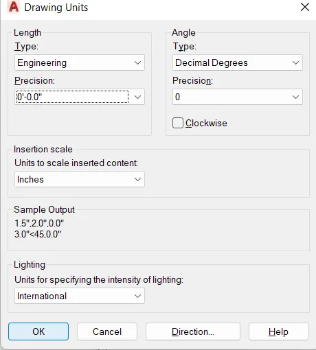
- So in order to set the units just type UN in the command line and then press Enter.
- A new dialouge box appears on the screen, in that dialouge box there will be an option called Length.
- In that option there are two more option called Type so in that box Select the type as Engineering and the other option is Precision so in the precision option give the precision option as 0'-0.0".
- There will be another option called Insertion scale, so put Inches in that option and then press OK as shown in the below figure:
- So after setting the Units we have to set the limits.
- But before setting the limits first of all we need to change the Workspace we have to change the 2D workspace into the 3D modelling.
- After changing the workplace we need to change the limits.
- So in order to change the limits just type LIM in the command line and then press Enter.
- Now set the lower left corner as the 0'-0.0",0'-0.0" and the upper right corner as the 1000',1000' and then press Enter.
- After setting the limits and the units we have to zoom out so in order to do so,just type z in the command line and then type e in the command line and then press enter. Now the workspace have been zoomed out.
- Now we have to create the plan that is already given in the figure, so in order to create a plan as shown in the figure,first of all select the top view because we have to create the 2D floor plan first and in order to create the 2D plan we need to set the 3D modelling space into the Top view.
- So after doing that first of all we need to create the boundaries.
- So in order to create the boundaries use the rectangular tool to create a rectangle.
- To invoke the rectangle command just type REC in the command line and then press Enter.
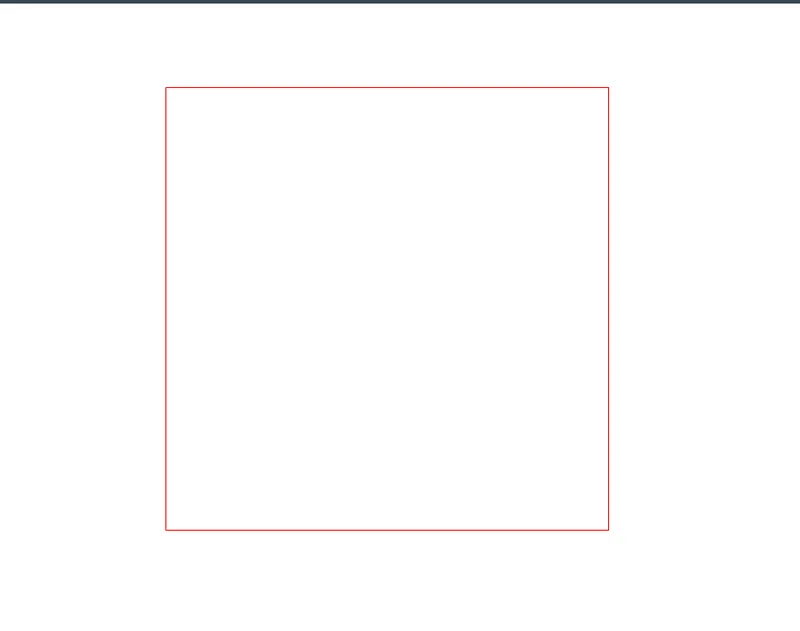
- After that specify the first point anywhere in the workspace and after specifying the first point just type d in the command line and then press Enter after pressing the Enter we need to provide the dimensions of the rectangle as given in thr above figure. So just give the rectangle diamension as 10'9",10'-9". Draw a square of this dimension as shown in the below figure:
- Now after creating the 10'9" square just explode the square by using the Explode tool.
- In order to explode the rectangle just type X in the command line and then press enter, now select the sqaure which we wanted to explode after selecting the square just press Enter and the rectangle have been exploded using the Explode command.
- Now after exploding the rectangle we need to create the inner walls.
- So in order to create the inner walls first we need to use the offset command.
- In order to use the offset command just type OFF in the command line and then press enter and give the offset diatnace as 9" and then press enter and give the offset of 9" in the inner side of the square at the two sides as shown in the below figure":
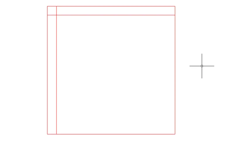
- The inner walls have been created using the offset command.
- Now use the trim command in order to delete the unwanted lines and erase them.
- So in order to use the Trim command just type TR in the command line and then press Enter.
- Now trim the all unwanted lines as shown in the below figure:
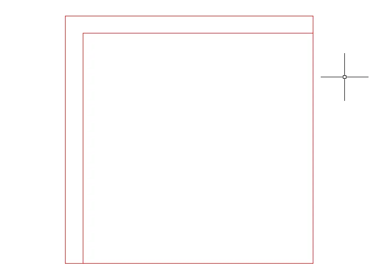
- Now the inner walls have been created perfectly.
- Now we have to create the windows and to create the windows we need to use the offset command.
- In order to use the offset command just type OFF in the command line and then press enter and give the offset diatnace as 3'-5" from the inner rectangle and then again use the offset command and give the offset distance as the 3'-6" and then press enter.
- And to create a window draw a line from the middle of the window frame and to draw a line use the Line command just type L in the command line and then press Enter and draw a line from the centre of the window as shown in the below figure:
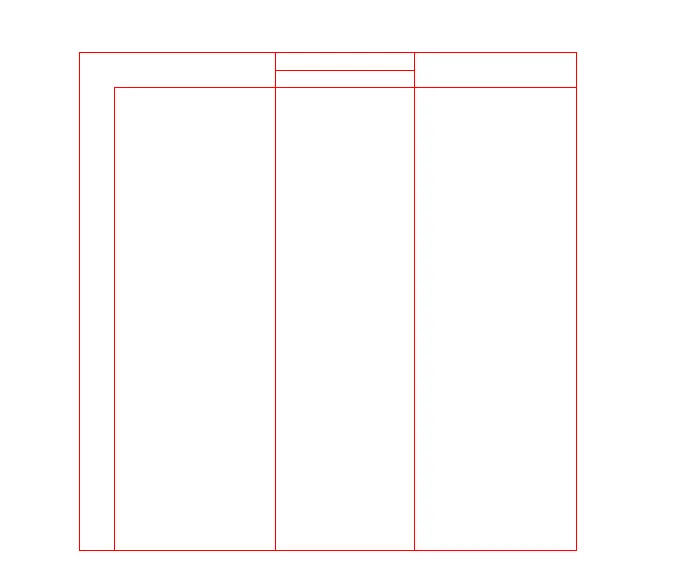
- Now use the trim command in order to delete the unwanted lines and erase them.
- So in order to use the Trim command just type TR in the command line and then press Enter.
- Now trim the all unwanted lines as shown in the below figure:
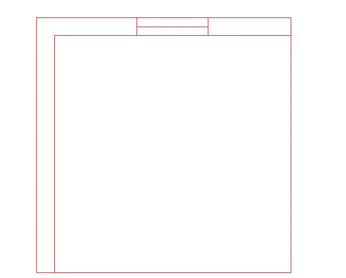
- Similarly use the same procedure to draw the window on the other side of the wall.
- In order to use the offset command just type OFF in the command line and then press enter and give the offset diatnace as 3'-6" from the inner rectangle and then again use the offset command and give the offset distance as the 3' and then press enter.
- And to create a window draw a line from the middle of the window frame and to draw a line use the Line command just type L in the command line and then press Enter and draw a line from the centre of the window as shown in the below figure:
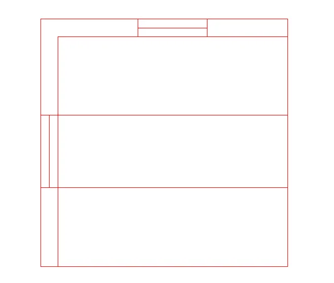
- Now use the trim command in order to delete the unwanted lines and erase them.
- So in order to use the Trim command just type TR in the command line and then press Enter.
- Now trim the all unwanted lines as shown in the below figure:
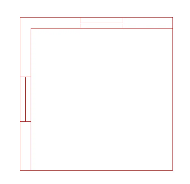
- Now the plan view is ready as shown in the above figure.
- Now using this plan view we have to create the 3D view.
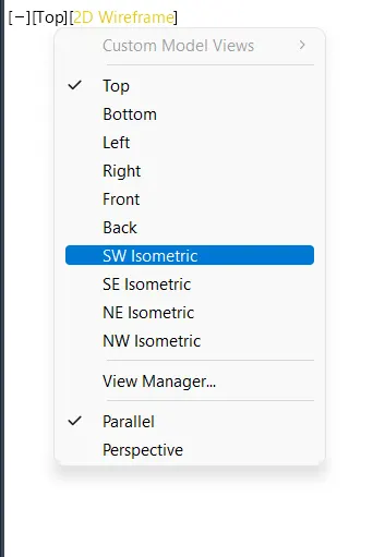
- Now after creating the plan in the top view now we have to change the view into the SW isometric view.
- And to change the SW isometric view we just need to click on the option 2D wireframe which is at the left upper corner of the screen,just from there choose option SW isometric as shown in the below figure:
- After changing the view into 3D isometric view,we have to set the boundaries to create the 3D wall.
- in order to set the boundary we need to just type BOUNDARY in the command line and then press Enter.
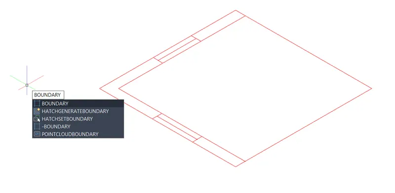
- A new dialouge box appears on the screen as shown in the below figure:
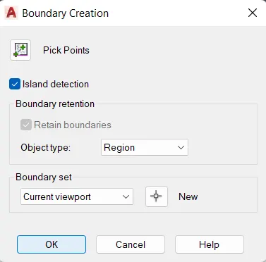
- And after clicking on the OK option just pick the points where we want to set the boundaries,i have selected the boundaries as shown in the below figure:
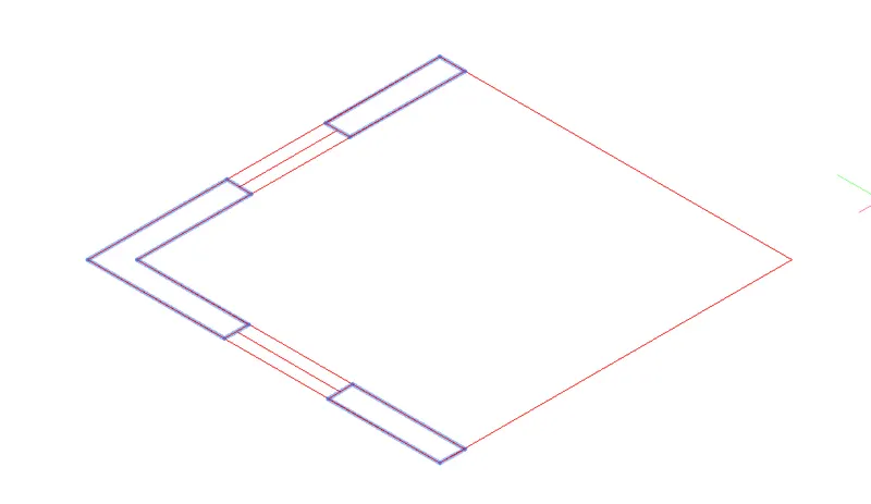
- The selected area is the area where we want to set the boundaries and to create the wall.
- And to create the wall we will be using the Extrude command, in order to use the Extrude command just type EXT in the command line and then press Enter and place the cursor where we want to do the extrution as shown in the below figure:
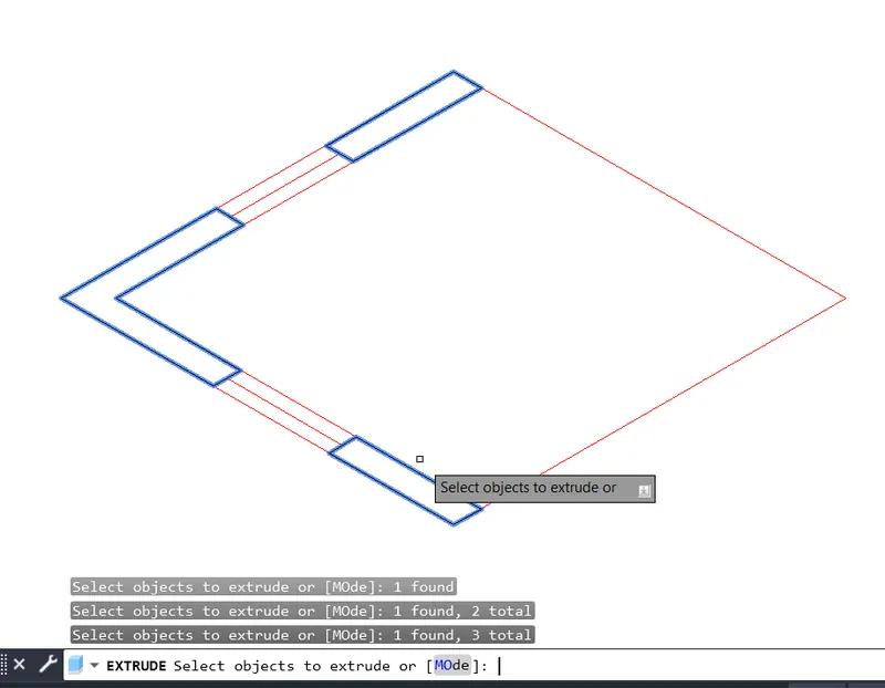
-And then press Enter.
- After pressing the enter give the dimensions to upto which level we want to extrude the walls.
- So here i am giving the height of 10'-9" as shown in the below figure:
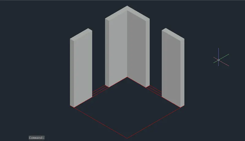
- Now the extrution of the walls have been done using the Extrude command as shown in the above figure.
- Now the walls have been created now we have to draw the windows.
- So in order to draw the windows first of all we need to use the Rectangle command and to use the rectangle command first we need to invoke the rectangle command just by typing REC in the command line and then press Enter.
- So after that just draw a rectangle on the windows that we had created before,draw a rectangle.
- After creating rectangle command just use the Extrude command once again in order to create the window.
- So to use the Extrude command just type EXT in the command line and then press Enter and place the cursor where we want to do the extrution, so place the cursor on the rectangle which we have created over the window.And do the extrusion.
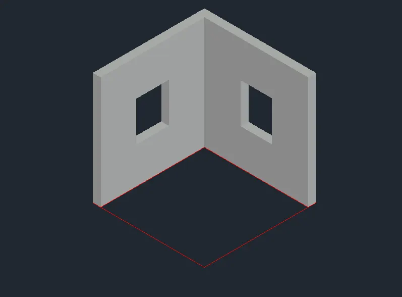
- First give the height of 3' from the bottom in the upward direction and the 3' from the top in the inward direction just as shown in the below figure:
- Now we have to draw the windows,in order to draw the windows on both the walls first of all we need to use the UCS option and to invoke the UCS command just type UCS in the command line and from the command line there is another option called FACE select that option.
- And now select the desired face of the wall and draw the window.
- In order to draw the window we need to need to use the rectangle command and to invoke the rectangle command just type REC in the command line and then press Enter.
- Now specify the first point.
- And type d in the command line and then press Enter.
- Now give the dimensions as the size of the window is 3' X 4'.
- After creating the rectangle of 3' X 4' we need to use the offset tool to create the inner rectangle using the offset command.
- In order to use the offset command just type OFF in the command line and then press enter and give the offset diatnace as 3" and then select the rectangle and give the offset of 3" in the inner side of the rectangle which we have just created of dimension 3' X 4'.
- Then again use the offset command and give the offset distance as the 3" and offset the last created rectangle in the inward direction and then press enter.
- Now after creating the offsets the boundaries of the windows have been created.
- After creating the boundaries we need to use the hatch command in order to create a good aesthetical look for the window.
- So in order to use the Hatch command just type HATCH in the command line and then enter. After that a new dialouge box opens in that dialouge box select the suitable hatch to provide at the window and use the pick point option to create hatches in the windows.
- After creating hatches now the window have been created as shown in the below figure:

- Now that the window have been created using the different command now we have to move this window to the desired place.
- So in order to move the window in the desired place just type M in the command line and then press Enter.
- Now choose the base point and move the window at their desired place as shown in the below figure:
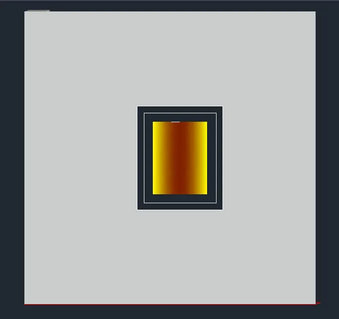
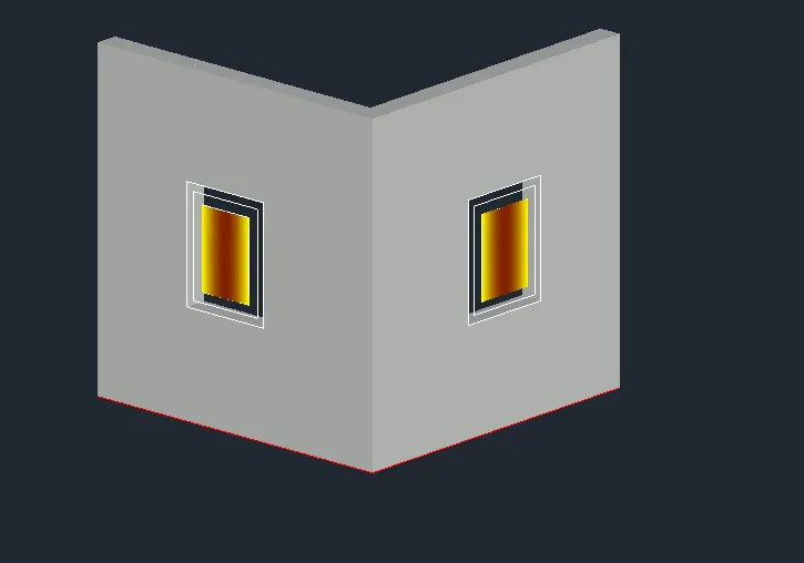
- Now do the same procedure for the another wall for placing the window as shown in the below image:
- For creating text and the dimensions, change the SW isometric view into the Top view from there we can give the dimensions.
- So in order to give the dimensions just type DIMLINEAR in the command line and then press Enter.
- And then select the first point of the wall which has to be measured and the select the second point of the wall. And then repeat this procedure for all the objects which we want to measure.
- And in order to write a text just type DTEXT in the command line and then give the height of the text and the angle of the text and then press Enter.
- Now write the desired text at the desired loacation.
- Now our geometry of crating walls with the windows have been created as shown in the above figures in a very detailed manner.
FINAL RESULT:
(i) 3D VIEW OF THE PLAN:
(ii) SECTION A:
(iii) SECTION B:
Question 2. Create the 3D View of the Building Façade as given in the plan and elevation. Also, see the detail of the window.
AIM: To create the 3D view of the Building facade with the plan and elevation.
INTRODUCTION: AutoCAD software provides user to create the 3D models using the various tools and the various commands like the pan command,UCS command and the various commands can be used in the 3D AutoCAD. A user is allowed to use the 3D in AutoCad using the 3D modelling workspace. The 3D AutoCAD makes the 3D creation much easier for the user who are willing to create 3D using the commands and the tools used in the AutoCAD software. In this section we will be able to understand how to create the isometric views in the 3D modelling space using the various tools and the various commands that are helpful in creating the 3D model. The detailed process have been discussed below.
PROCEDURE:
- So in order to create the 3D isometric view of the building with the plan and the elevation is given,first of all go to the AutoCAD software.
- Open the software and then select the option scratch and then open a new file option and then press Enter.
- After opening the new file we have to set the units and the limits.
- So in order to set the units just type UN in the command line and then press Enter.
- A new dialouge box appears on the screen, in that dialouge box there will be an option called Length.
- In that option there are two more option called Type so in that box Select the type as Engineering and the other option is Precision so in the precision option give the precision option as 0'-0.0".
- There will be another option called Insertion scale, so put Inches in that option and then press OK as shown in the below figure:
- So after setting the Units we have to set the limits.
- But before setting the limits first of all we need to change the Workspace we have to change the 2D workspace into the 3D modelling.
- After changing the workplace we need to change the limits.
- So in order to change the limits just type LIM in the command line and then press Enter.
- Now set the lower left corner as the 0'-0.0",0'-0.0" and the upper right corner as the 1000',1000' and then press Enter.
- After setting the limits and the units we have to zoom out so in order to do so,just type z in the command line and then type e in the command line and then press enter. Now the workspace have been zoomed out.
- Now we have to create the plan that is already given in the figure, so in order to create a plan as shown in the figure,first of all select the top view because we have to create the 2D floor plan first and in order to create the 2D plan we need to set the 3D modelling space into the Top view.
- So after doing that first of all we need to create the boundaries.
- So in order to create the boundaries use the rectangular tool to create a rectangle.
- To invoke the rectangle command just type REC in the command line and then press Enter.
- After that specify the first point anywhere in the workspace and after specifying the first point just type d in the command line and then press Enter after pressing the Enter we need to provide the dimensions of the rectangle as given in the above figure. So just give the rectangle diamension as 10'9"x 6'-9". Draw a rectangle of this dimension as shown in the below figure:
- Now after creating the 10'9" X 6'-9" rectangle just explode the rectangle by using the Explode tool.
- In order to explode the rectangle just type X in the command line and then press enter, now select the rectangle which we wanted to explode after selecting the rectangle just press Enter and the rectangle have been exploded using the Explode command.
- Now after exploding the rectangle we need to create the inner walls.
- So in order to create the inner walls first we need to use the offset command.
- In order to use the offset command just type OFF in the command line and then press enter and give the offset distance as 9" and then press enter and give the offset of 9" in the inner side of the square at the two sides as shown in the below figure:
- The inner walls have been created using the offset command.
- Now use the trim command in order to delete the unwanted lines and erase them.
- So in order to use the Trim command just type TR in the command line and then press Enter.
- Now trim the all unwanted lines as shown in the below figure:
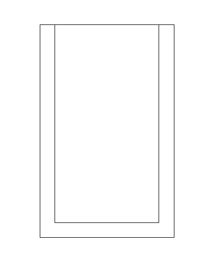
- Now the inner walls have been created perfectly.
- Now we have to create the windows and to create the windows we need to use the offset command.
- In order to use the offset command just type OFF in the command line and then press enter and give the offset distance as 1'-11" from the inner rectangle and then again use the offset command and give the offset distance as the 3' and then press enter as shown in the below figure:
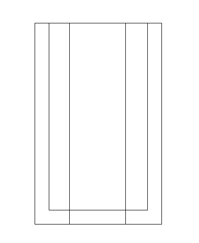
- Now use the trim command in order to delete the unwanted lines and erase them.
- So in order to use the Trim command just type TR in the command line and then press Enter.
- Now trim the all unwanted lines.
- And to create a window draw a line from the middle of the window frame and to draw a line use the Line command just type L in the command line and then press Enter and draw a line from the centre of the window as shown in the below figure:
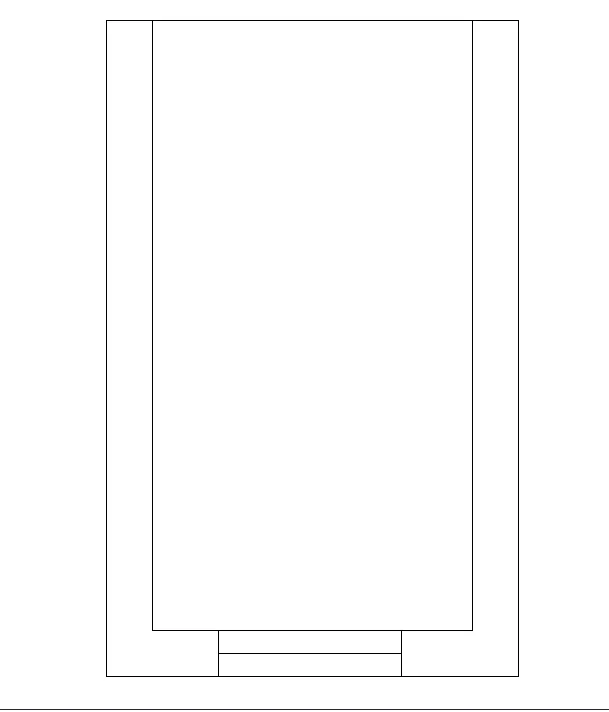
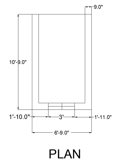
- Now the plan view is ready as shown in the above figure.
- Now using this plan view we have to create the 3D view.
- Now after creating the plan in the top view now we have to change the view into the SW isometric view.
- And to change the SW isometric view we just need to click on the option 2D wireframe which is at the left upper corner of the screen,just from there choose option SW isometric as shown in the below figure:
- After changing the view into 3D isometric view,we have to set the boundaries to create the 3D wall.
- in order to set the boundary we need to just type BOUNDARY in the command line and then press Enter.
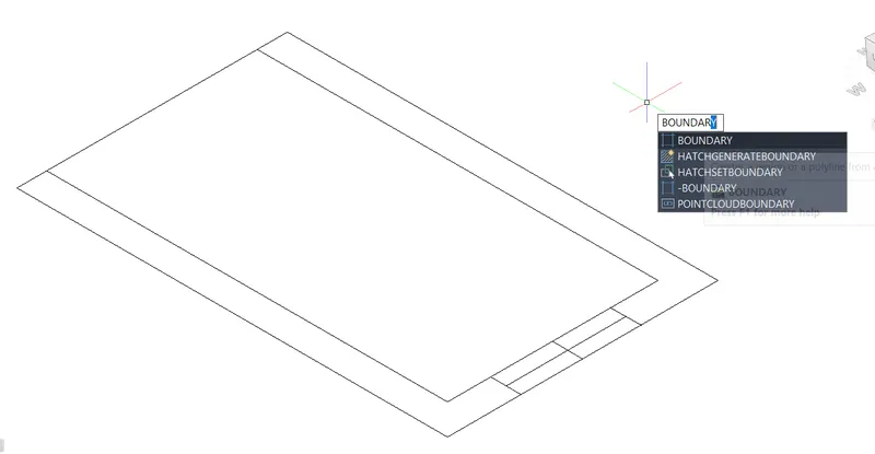
- A new dialouge box appears on the screen as shown in the below figure:
- And after clicking on the OK option jus pick the points where we want to set the boundaries,i have selected the boundaries as shown in the below figure:
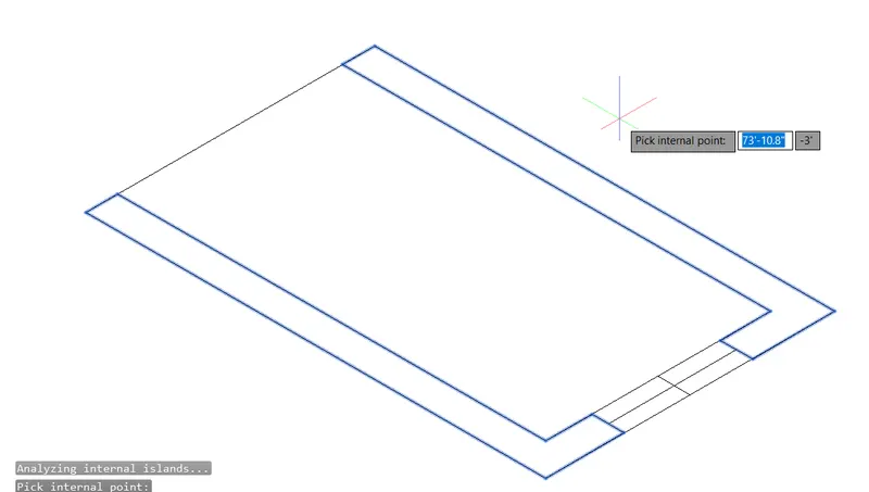
- The blue line in the above image indicates the boundary selection.
- The selected area is the area where we want to set the boundaries and to create the wall.
- And to create the wall we will be using the Extrude command, in order to use the Extrude command just type EXT in the command line and then press Enter and place the cursor where we want to do the extrution as shown in the below figure:
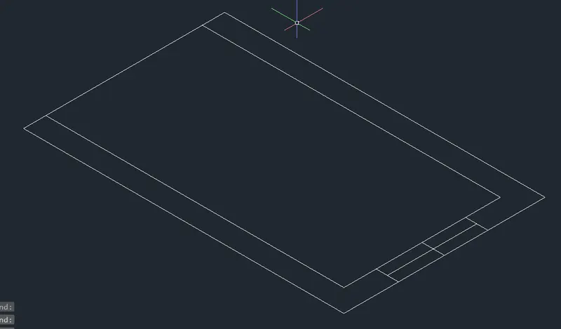
-And then press Enter.
- After pressing the enter give the dimensions to upto which level we want to extrude the walls.
- So here i am giving the height of 10'-9" as shown in the below figure:
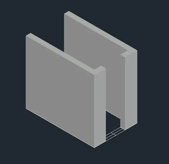
- Now the extrution of the walls have been done using the Extrude command as shown in the above figure.
- Now the walls have been created now we have to draw the windows.
- So in order to draw the windows first of all we need to use the Rectangle command and to use the rectangle command first we need to invoke the rectangle command just by typing REC in the command line and then press Enter.
- So after that just draw a rectangle on the windows that we had created before,draw a rectangle.
- After creating rectangle command just use the Extrude command once again in order to create the window.
- So to use the Extrude command just type EXT in the command line and then press Enter and place the cursor where we want to do the extrution, so place the cursor on the rectangle which we have created over the window.And do the extrusion.
- First give the height of 3' from the bottom in the upward direction and the 3' from the top in the inward direction just as shown in the below figure:
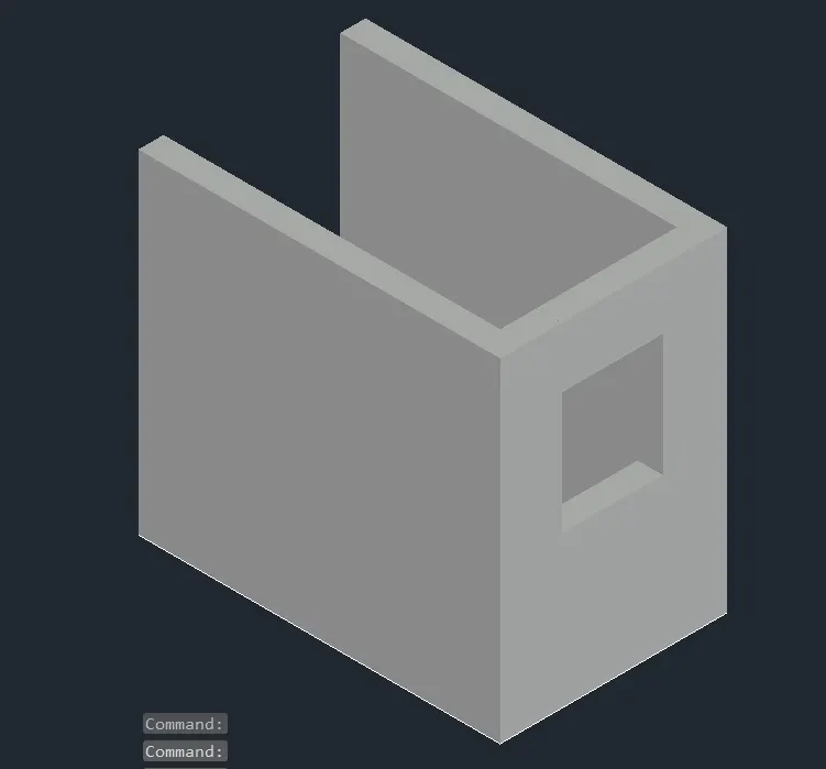
- Now we have to draw the windows,in order to draw the windows on both the walls first of all we need to use the UCS option and to invoke the UCS command just type UCS in the command line and from the command line there is another option called FACE select that option.
- And now select the desired face of the wall and draw the window.
- In order to draw the window we need to need to use the rectangle command and to invoke the rectangle command just type REC in the command line and then press Enter.
- Now specify the first point.
- And type d in the command line and then press Enter.
- Now give the dimensions as the size of the window is 3' X 4'.
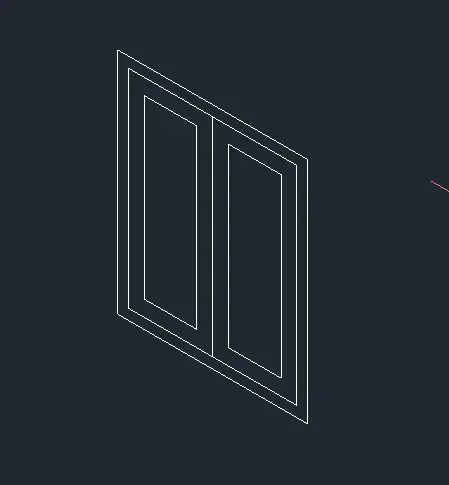
- After creating the rectangle of 3' X 4' we need to use the offset tool to create the inner rectangle using the offset command.
- In order to use the offset command just type OFF in the command line and then press enter and give the offset distance as 2" and then select the rectangle and give the offset of 3" in the inner side of the rectangle which we have just created of dimension 3' X 4'.
- Then again use the offset command and give the offset distance as the 3" and offset the last created rectangle in the inward direction and then press enter.
- Now after creating the offsets the boundaries of the windows have been created as shown in the below figure:
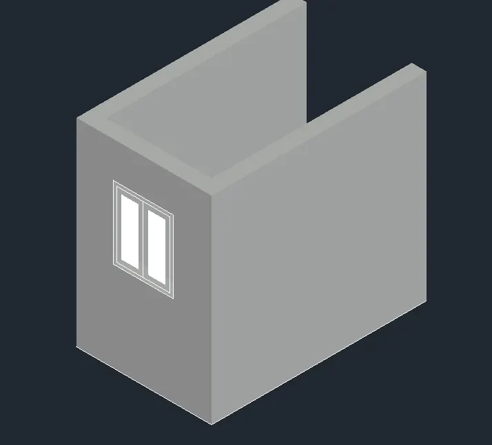
- Now that the window have been created using the different command now we have to move this window to the desired place.
- So in order to move the window in the desired place just type M in the command line and then press Enter.
- Now choose the base point and move the window at their desired place as shown in the below figure:
- Now the first floor of the building is ready. And we want to create the G+3 floor so in order to create the 3 more floor just copy the ground floor 3 times.
- And in order to copy the floor just type CO in the command line and then press Enter and select the floor and now specify the base point and after specifying the base point copy that base point 3 times in order to get the 3 more floors as shown in the above figure:
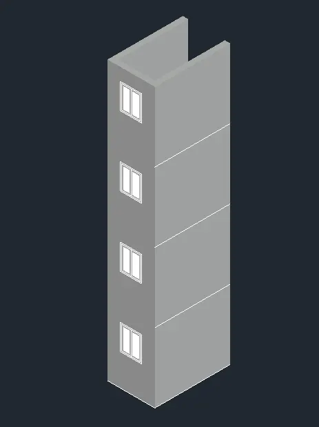
- The 3D isometric view of the building is almost ready. In order to complete the building we need to draw one more element.
- And in order to create that element first we need to use the line command.
- And to invoke the line command type L in the command line and then press Enter.
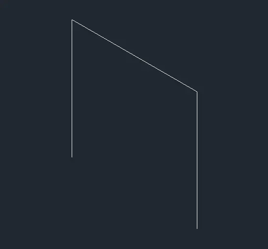
- Then draw a line of 6'-5" in the upward direction and then draw another line of 6'-9" and another line of 6'-5" exactly as shown in the below image:
- Now draw a rectangle of 4" X 9". And in order to create the rectangle just type REC in the command line and then press Enter.
- Now specify the first point and then type d in the command line and give the dimensions as 4" X 9". The rectangle is ready.
- After creating the rectangle use the Extrude command in order to use the Extrude command just type EXT in the command line and then press Enter and place the cursor where we want to do the extrution as shown in the below figure:
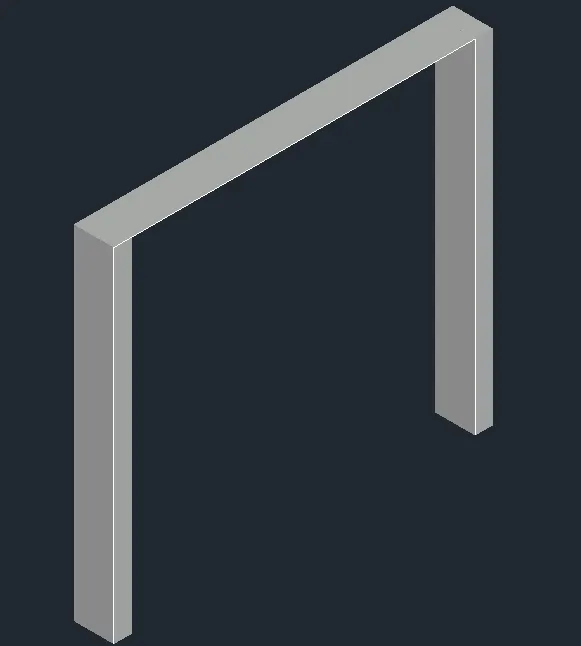
- Now the railing has been prepared using the line,rectangular and the extrude command as sholwn in the above figure.
- Now we have to move this railing to the desired place.
- So in order to move the railing in the desired place just type M in the command line and then press Enter.
- Now choose the base point and move the window at their desired place as shown in the below figure:
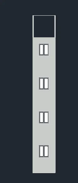
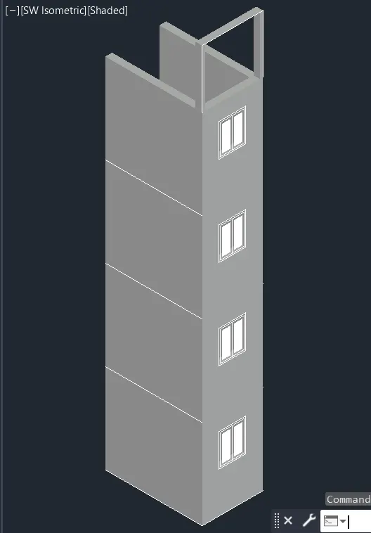
- And now the building is ready with the front elevation and the 3D image of the building.
FINAL RESULT:
(i) PLAN:
(ii) ELEVATION:
(iii) 3D ELEVATION:
Question 3. Create the ismoteric 3d view of a stair with railing as shown in the plan and elevation. Assume the size of the balustrades and the hand rails.
AIM: To create a ismoteric 3d view of a stair with railing as shown in the plan and elevation. Assume the size of the balustrades and the hand rails.
INTRODUCTION: AutoCAD software provides user to create the 3D models using the various tools and the various commands like the pan command,UCS command and the various commands can be used in the 3D AutoCAD. A user is allowed to use the 3D in AutoCad using the 3D modelling workspace. The 3D AutoCAD makes the 3D creation much easier for the user who are willing to create 3D using the commands and the tools used in the AutoCAD software. In this section we will be able to understand how to create the isometric views in the 3D modelling space using the various tools and the various commands that are helpful in creating the 3D model. The detailed process have been discussed below.
PROCEDURE:
- So in order to create the 3D isometric view of the building with the plan and the elevation is given,first of all go to the AutoCAD software.
- Open the software and then select the option scratch and then open a new file option and then press Enter.
- After opening the new file we have to set the units and the limits.
- So in order to set the units just type UN in the command line and then press Enter.
- A new dialouge box appears on the screen, in that dialouge box there will be an option called Length.
- In that option there are two more option called Type so in that box Select the type as Engineering and the other option is Precision so in the precision option give the precision option as 0'-0.0".
- There will be another option called Insertion scale, so put Inches in that option and then press OK as shown in the below figure:
- So after setting the Units we have to set the limits.
- But before setting the limits first of all we need to change the Workspace we have to change the 2D workspace into the 3D modelling.
- After changing the workplace we need to change the limits.
- So in order to change the limits just type LIM in the command line and then press Enter.
- Now set the lower left corner as the 0'-0.0",0'-0.0" and the upper right corner as the 1000',1000' and then press Enter.
- After setting the limits and the units we have to zoom out so in order to do so,just type z in the command line and then type e in the command line and then press enter. Now the workspace have been zoomed out.
- Now we have to create the plan that is already given in the figure, so in order to create a plan as shown in the figure,first of all select the top view because we have to create the 2D floor plan first and in order to create the 2D plan we need to set the 3D modelling space into the Top view.
- So after doing that first of all we need to create the boundaries.
- So in order to create the boundaries use the rectangular tool to create a rectangle.
- To invoke the rectangle command just type REC in the command line and then press Enter.
- After that specify the first point anywhere in the workspace and after specifying the first point just type d in the command line and then press Enter after pressing the Enter we need to provide the dimensions of the rectangle as given in the above figure. So just give the rectangle diamension as 12' x 4'. Draw a rectangle of this dimension.
- After creating the 12' X 4' dimension use the offset command to create the riser and the treader.
- So in order to create the tread first we need to use the offset command.
- In order to use the offset command just type OFF in the command line and then press enter and give the offset distance as 1' and then press enter and give the offset of 1' in the inner side of the rectangle at the bottom sides.
- Repeat the offset command for atleast 8 times in order to create the tread of 1' and after creating the treads now create the landing of 3'. So just type OFF in the command line and then press Enter.
- Now give the offset distance as 3' and give the offset to the top most line of the rectangle in order to create the landing.
- Now the staircase plan is ready as shown in the below figure:
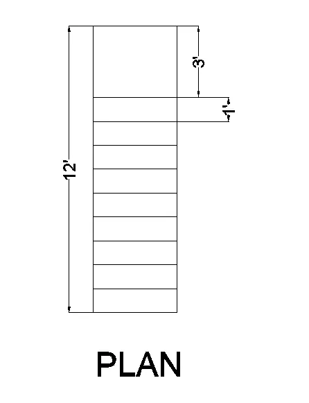
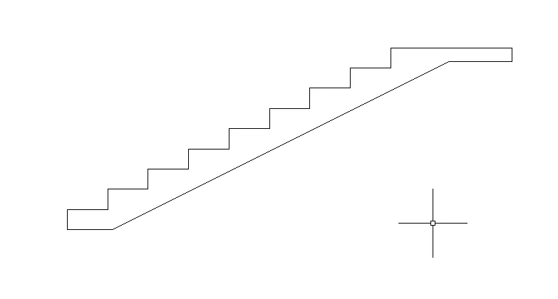
- Now the plan view is ready as shown in the above figure.
- Now using this plan view we have to create the 3D view.
- Now after creating the plan in the top view now we have to change the view into the SW isometric view.
- And to change the SW isometric view we just need to click on the option 2D wireframe which is at the left upper corner of the screen,just from there choose option SW isometric as shown in the below figure:
- After changing the view into 3D isometric view,we have to set the boundaries to create the staircase.
- In order to set the boundary we need to just type BOUNDARY in the command line and then press Enter.
- And then press Enter.
- After pressing the enter give the dimensions to upto which level we want to extrude the stairs.
- So here i am giving the height of 6".
- Again use the extrude command and give the height of 1'.
- Similarly again use the extrude command and give the height of 1'-6" for the third tread.
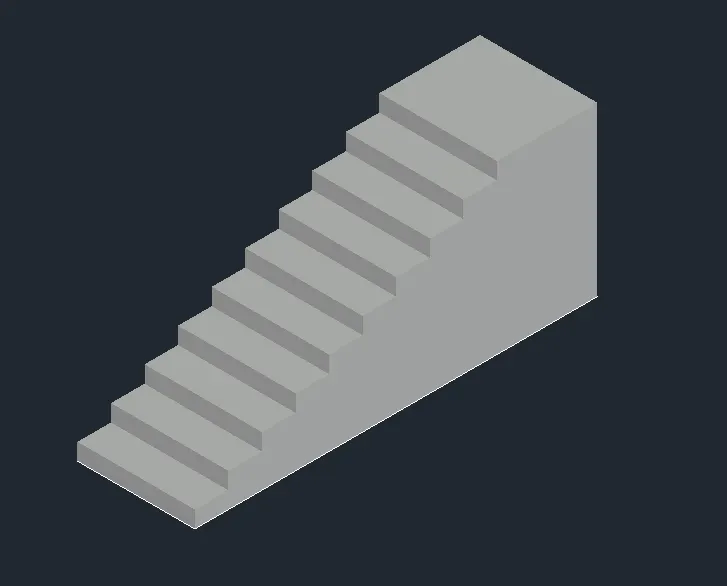
- Do the same procedure untill the last step including the landing as shown in the below figure:
- Now use the option command Solid union.
- Just go to the Home tab, there we will be able to find the option solid union as shown in the below image:
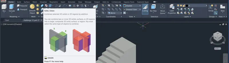
- We use the solid union option to combines the 3D solids so if we select the stairs we can see in the below image all the blocks are separate, so in order to combine them we need to use the solid union option.
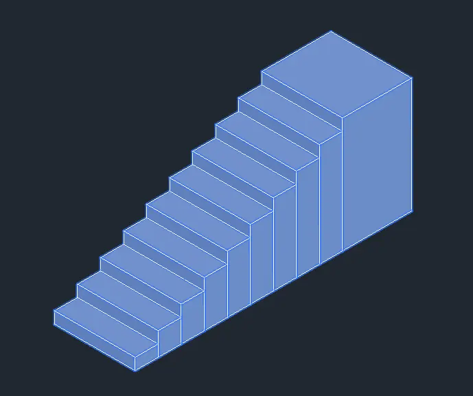
- So in order to do that just select the whole 3D solid i.e, staircase and just click on the option solid union and now all the blocks that are separated before are now combined as shown in the below figure:
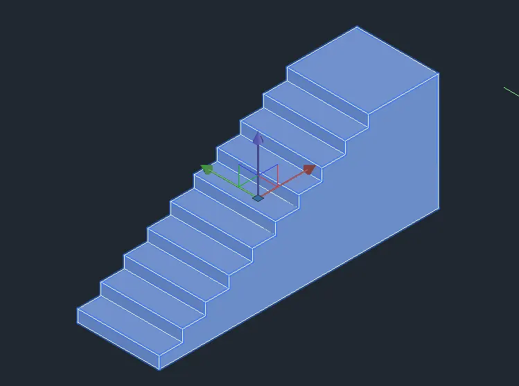
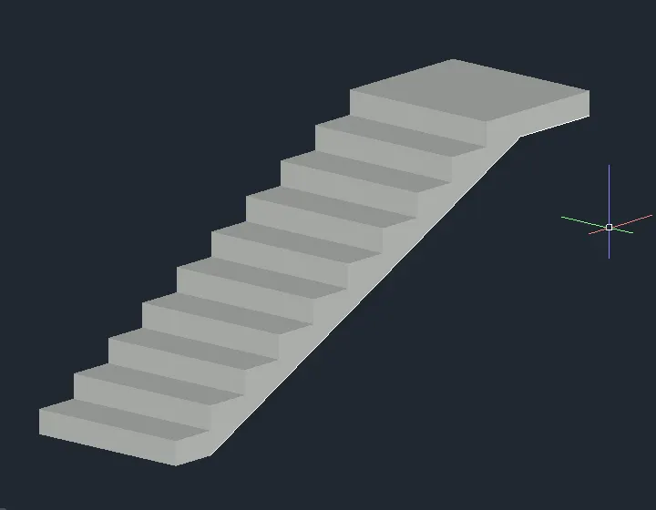
- After combining all the blocks, now we are going to use the Presspull command to pull out the extra part of the stair.
- So to use the presspull command just go to the Home tab there we will be able to find the option presspull as shown in the below image:
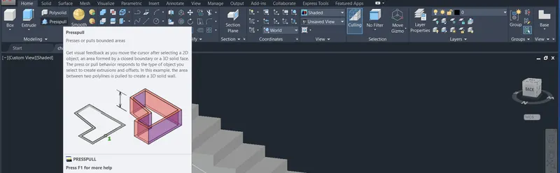
- By using the presspull command we can pull out the extra part of the staircase as shown in the below image:
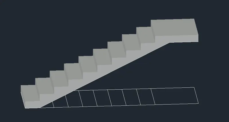
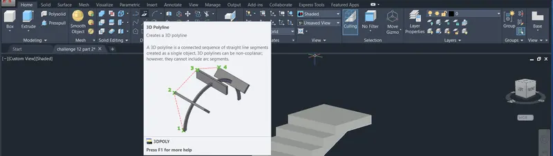
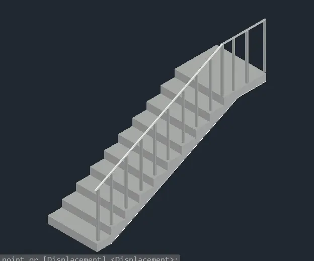
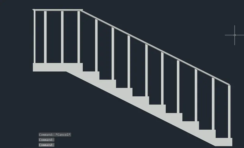
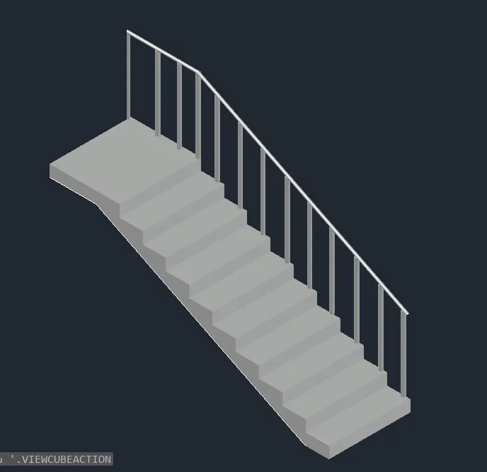
- After that we have to create the railings we need to use the 3D polyline. And we can find the polyline in the Home tab as shown in the below figure:
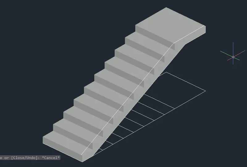
- Now draw a line at the edge of the stair using the 3D polyline as shown in the below image:
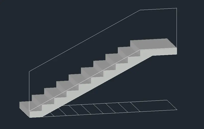
- Now copy that railing upto a certain height.
- To copy the railing we will be using the Copy command and in order to invoke the copy command just type CO in the command line and then press Enter.
- And give the copied ployline a height of 3'-2" just as shown in the below image:
- And now draw the railings using the sweep command as shown in the below figure:
FINAL RESULT:
(i) PLAN:
(ii) 3D SIDE ELEVATION:
Question 4. Create the 3D view of a Wall with spread footing . Create the Door opening only. Assume the size of the parpaet and the coping. See the plans and elevation for the details. Also, create a rendered view of the model with materials as of your choice.
AIM: To create the 3D view of a Wall with spread footing. And to create the Door opening only.
INTRODUCTION: AutoCAD software provides user to create the 3D models using the various tools and the various commands like the pan command,UCS command and the various commands can be used in the 3D AutoCAD. A user is allowed to use the 3D in AutoCad using the 3D modelling workspace. The 3D AutoCAD makes the 3D creation much easier for the user who are willing to create 3D using the commands and the tools used in the AutoCAD software. In this section we will be able to understand how to create the isometric views in the 3D modelling space using the various tools and the various commands that are helpful in creating the 3D model. The detailed process have been discussed below.
PROCEDURE:
- So in order to create the 3D isometric view of the building with the plan and the elevation is given,first of all go to the AutoCAD software.
- Open the software and then select the option scratch and then open a new file option and then press Enter.
- After opening the new file we have to set the units and the limits.
- So in order to set the units just type UN in the command line and then press Enter.
- A new dialouge box appears on the screen, in that dialouge box there will be an option called Length.
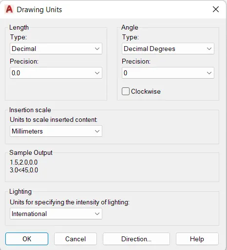
- In that option there are two more option called Type so in that box Select the type as Decimal and the other option is Precision so in the precision option give the precision option as 0.0.
- There will be another option called Insertion scale, so put Milimeters in that option and then press OK as shown in the below figure:
- So after setting the Units we have to set the limits.
- But before setting the limits first of all we need to change the Workspace we have to change the 2D workspace into the 3D modelling.
- After changing the workplace we need to change the limits.
- So in order to change the limits just type LIM in the command line and then press Enter.
- Now set the lower left corner as the 0,0 and the upper right corner as the 2000,2000 and then press Enter.
- After setting the limits and the units we have to zoom out so in order to do so,just type z in the command line and then type e in the command line and then press enter. Now the workspace have been zoomed out.
- Now we have to create the plan that is already given in the figure, so in order to create a plan as shown in the figure,first of all select the top view because we have to create the 2D floor plan first and in order to create the 2D plan we need to set the 3D modelling space into the Top view.
- So after setting the units and the limits,first thing we have to do is setting the plane using the UCS command.
- So in order to do so first change the view into the front view after that use the UCS command to adjust the plane.
- Just type UCS in the command line and then press Enter then there will be another option present in the command line called View just click on that option and enter.
- Now we will be using the Rectangle command and to invoke the rectangle command first we need to type REC in the command line and then press Enter.
- Now specify the first point anywhere in the workplace then type d in the command line and then press enter and now give the dimensions as 900 X 2100 in order to create the rectangle as shown in the below image:
- After creating this rectangle we have to create the foot steps and in order to do that use the offset command.
- And to invoke the offset command just type OFF in the command line and then press Enter and give the offset distance as 400. But before giving the offset to the upper line of the rectangle we ahve to use the Explode command in order to explode the rectangle.
- So to do so just type X in the command line and then press.
- Now select the rectangle which we want to explode and then press Enter.
- Now the rectangle has been exploded.
- Now we can use the offset command with 400 offset distance.
- After offsetting the upper line with a offset distance of 400 now we have to use the offset command with the right hand side and the left hand side line of the rectangle.
- So to invoke the offset command just type OFF in the command line and then press Enter and give the offset distance as 150 on either sides.
- And do the same procedure with the last step. Give the offset command and to invoke the offset command just type OFF in the command line and then press Enter and give the offset distance as 600.
- After offsetting the upper line with a offset distance of 600 now we have to use the offset command with the right hand side and the left hand side line of the rectangle.
- So to invoke the offset command just type OFF in the command line and then press Enter and give the offset distance as 50 on either sides.
- After that use the trim command in order to delete all the unnecessary lines as shown in the below figure:
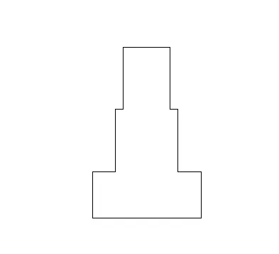
- Now after that use the offset command with 2100 offset distance.
- And to invoke the offset command just type OFF in the command line and then press Enter and give the offset distance as 2100. But before giving the offset to the upper line of the rectangle we ahve to use the Explode command in order to explode the rectangle.
- After offsetting the upper line with a offset distance of 2100.
- Now do the same procedure for completing the who;e process of creating the Wall with the spread footing as shown in the below figure:
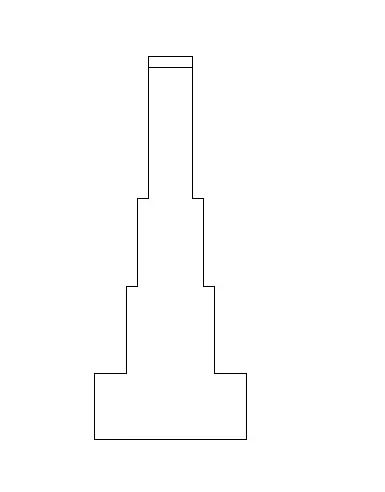
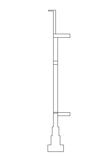
- Now the Plan of Wall with spread footing is ready as shown in the below figure:
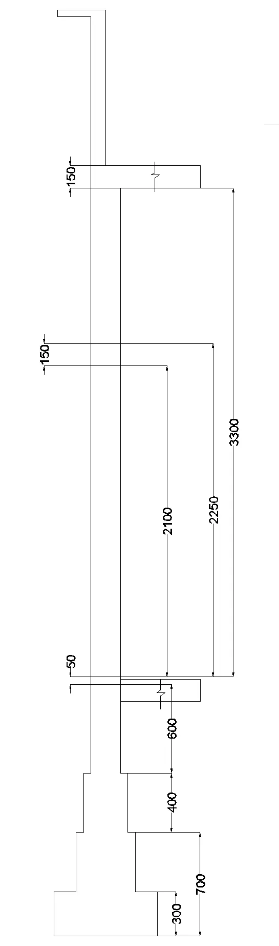
- After creating the plan for the spread footing with the wall now we have to create the 3D view also.
- So in order to do so first adjust the UCS to get the desired view.
- Now the plan view is ready as shown in the above figure.
- Now using this plan view we have to create the 3D view.
- Now after creating the plan in the top view now we have to change the view into the SW isometric view.
- And to change the SW isometric view we just need to click on the option 2D wireframe which is at the left upper corner of the screen,just from there choose option SW isometric as shown in the below figure:
- After changing the view into 3D isometric view,we have to set the boundaries to create the wall with spread footing.
- In order to set the boundary we need to just type BOUNDARY in the command line and then press Enter.
- And then press Enter.
- A new dialouge box appears on the screen as shown in the below figure:
- And after clicking on the OK option jus pick the points where we want to set the boundaries,i have selected the boundaries as shown in the below figure:
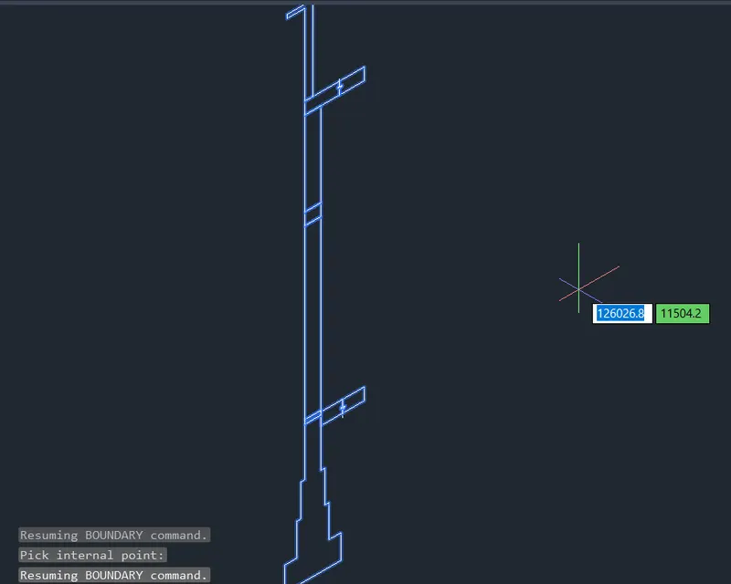
- The blue line in the above image indicates the boundary selection.
- The selected area is the area where we want to set the boundaries and to create the wall.
- And to create the wall we will be using the Extrude command, in order to use the Extrude command just type EXT in the command line and then press Enter and place the cursor where we want to do the extrution as shown in the below image:
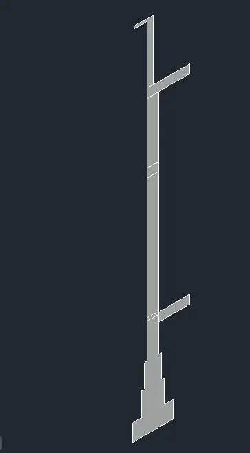
- And then press Enter.
- After pressing the enter give the dimensions to upto which level we want to extrude the wall with spread footing.
- So here i am giving the height of 8000 as shown in the below figure:
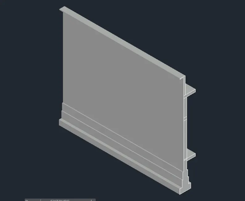
- Now we have to create the block for the window also.
- Here i am considering the height and the width of the window is 900 X 2100.
- Now draw rectangle using the rectangle and in order to invoke the command first we need to type REC in the command line and then press Enter.
- But in order to draw a window we need to select the plane also so in order to select the plane we first need to use the UCS command in order to set the plane.
- So just type UCS in the command line and then press Enter.
- Now there is an option called Face in the command line click on that option and create the plane in order to draw a window in that particular plane.
- Now we can draw the rectangle at that plane.
- So just draw a rectangular,specify the first point and then type d in the command line and then press Enter.
- Now give the dimensions as 900 X 2100 and the rectangle over the surface is ready.
- Now we have to make hole in order to create a window so in order to do so use the option go to the home tab there we will be able to find the option solid,substract as shown in the below figure:
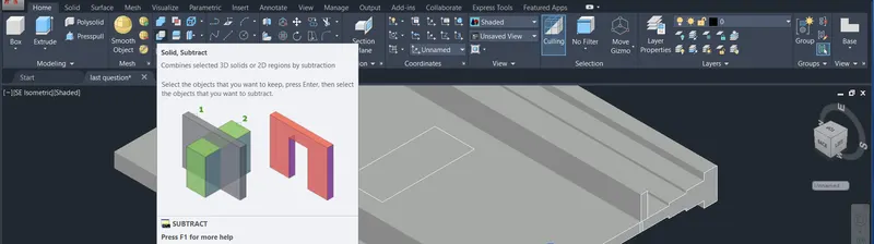
- By using this option we can make the window as shown in the below figure:
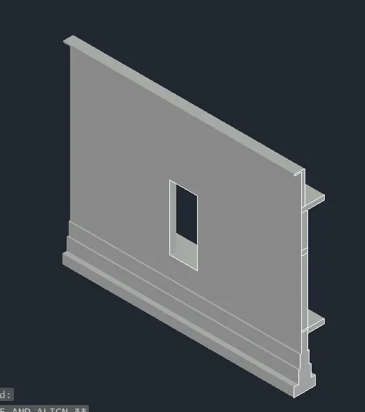
- Similarly draw the chajja over the window as shown in the below figure:
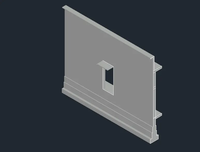
- Our 3D view of a Wall with spread footing is ready as shown in the above figure.
- And now we can also change the material in this workspace.
- And to change the material just type MAT in the command line and then press Enter.
- Select the material option then a new window with different materials opens as shown in the figure:
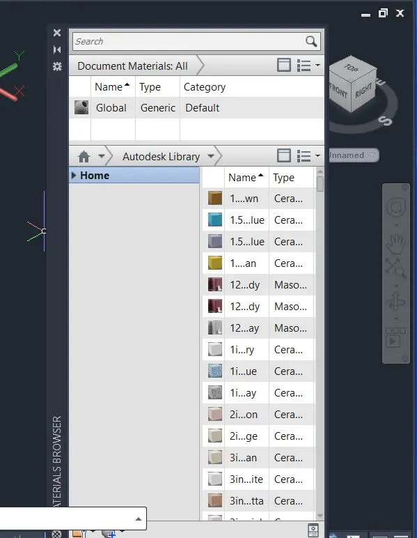
- Now we can change the different materials using this option.
FINAL RESULT :
(i) PLAN:
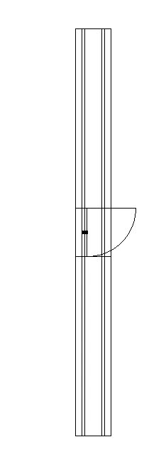
(ii) SECTION OF WALL FOOTING:
(iii) 3D VIEW OF WALL WITH SPREAD FOOTING: