Creating 3D Isometric view of various structural elements in AutoCAD
1)
AIM:
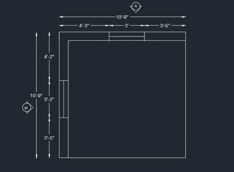
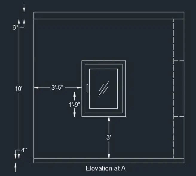
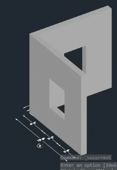
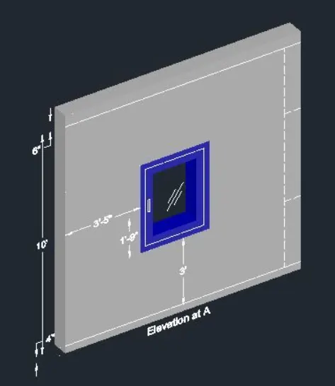
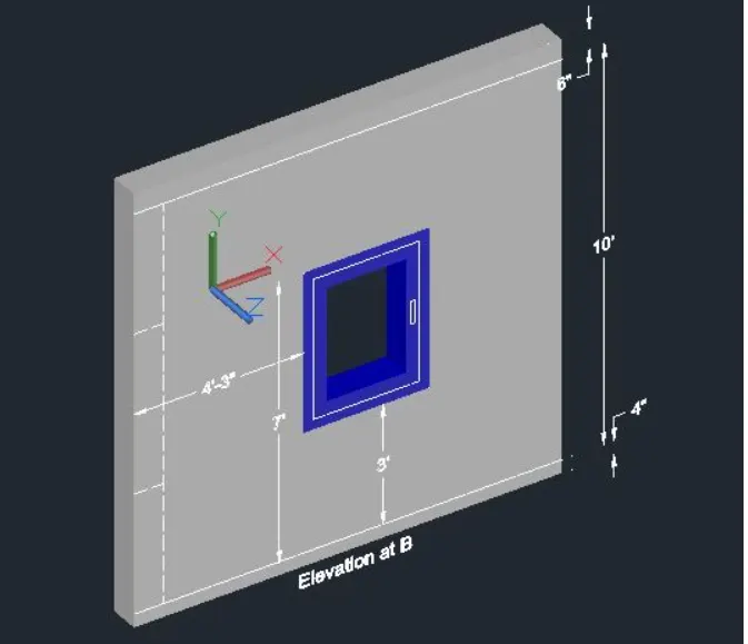
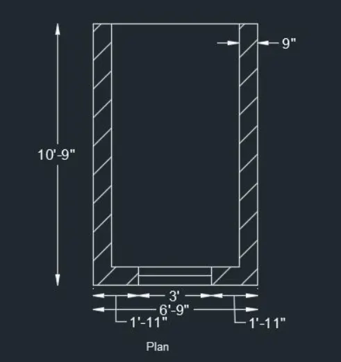
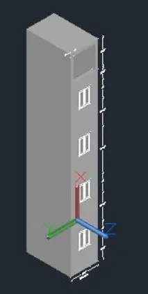
To Create a 3D isometric view of the the building with plan and elevation using Autocad
PROCEDURE:
- In the command prompt type units >engineering>0-0
- In the command prompt type limmax 100,100
- In the command prompt type limits 0,0
- In the command prompt type zoom a
- Go to the top vieW
- in the command prompt type I to draw the lines of distance 10-9,3,3-2 and thickness of 9''
- and draft the rectangle using rec command south west isometric iewand extrude it to 9''
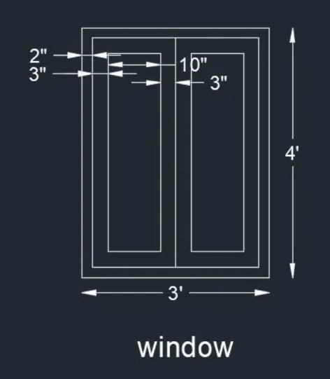
- sing subcommandsubractithe windoWS
- the command Prompttypeitohatchithe windows
- in the command prmpte recanidtogive the window detiling
result
2)
AIM:
To Create the building facade as given in the plan and elevation
PROCEDURE:
- In the command prompt EYPe uhitsRengineering uu
- In the conmmand premet tyPE limme 10o10p
- In the command prompt type limits o1oO|
- Go to the top yiew
- In the command prompt raft the desired lines
- In the hatch the plan
- dimto give the dimensions to give the text
- now gO TO south isometri view
- In the command prompt type reg to region the plan
- In the con pe extrude to extrude the plan
Result :
3)
AIM:
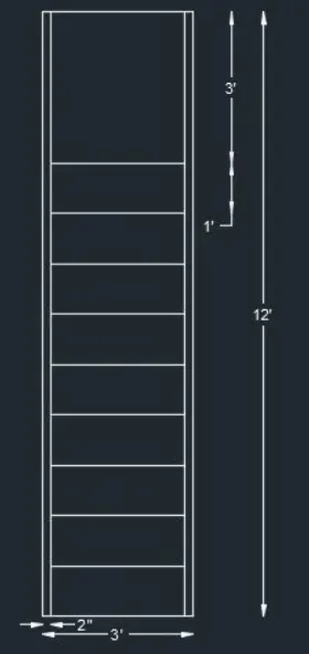
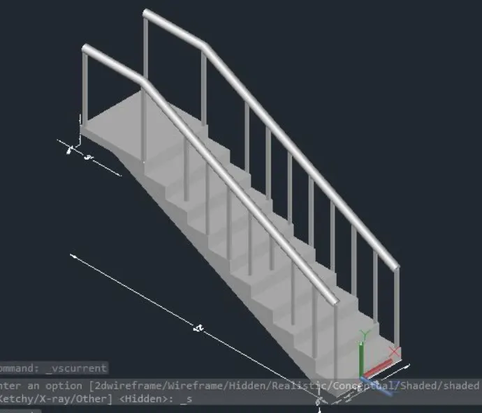
to coreat the stair with railing as shown in the plan and elevation using 3D autocad software
PROCEDURE
- in the commend promp type units >engineering>0'-0''
- in the command prompt type limmex >100'100'
- n the command prompt type limits > 0',0'
- Go to the top view
- In the command prompt typelland draft
- tn the top view the plan is crerted
Result :
4)
AIM:
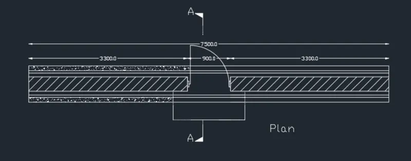
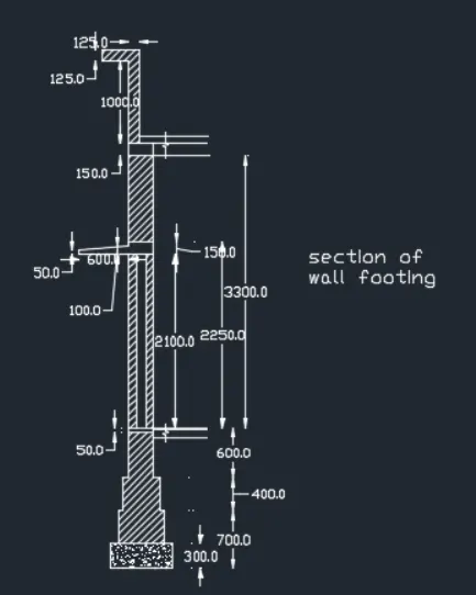
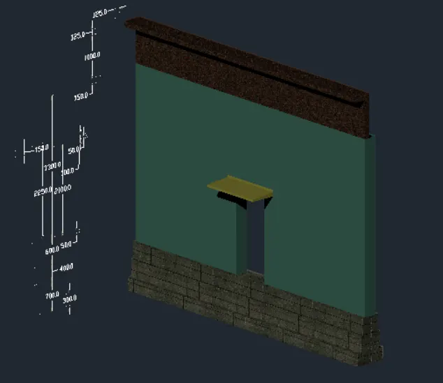
to coreat the Create the 3D view of a Wall with spread footing using 3D autocad software
PROCEDURE
- in the commend promp type units >engineering>0'-0''
- in the command prompt type limmex >100'100'
- n the command prompt type limits > 0',0'
- Go to the top view
- In the command prompt typelland draft
- tn the top view the plan is crerted
Result :