Creating 3D Isometric view of various structural elements in AutoCAD
AIM- Create a 3D Isometric View of the building with plan and elevation given.
PROCEDURE -
Commands Used in this challenge
Line
Rectangle
Trim
Move
Copy
Explode
Circle
Dimlinear
Dimcontinue
Boundary
3Dorbit
3D rotate
Extrude
Region
UCS
Camera
Block
Render RR
Sweep
Create Light
Step 1: Creating Layers
Open Layer properties and create new layers by clicking on new layer or right click on any layer and select new layer to create new layer
Layers are created as follows
Step 2: Creating Layers
Change the current layer to 3D_Wall
Create a rectangle of dimensions at any point on the screen
Offset the rectangle to inside to distance of as wall thickness
Delete the left and bottom lines and extend them to the edges as shown in figure
Step 3: Creating 3D View
Change the view to 3d by clicking on home button of view cube Set UCS as world
Create the boundaries for the walls using ‘BO’ command
Extrude the boundaries created to total height of DIM
Select all the wall and use group command to group then together
Draw rectangles at both windows and change them to boundaries using boundary command
Extrude both rectangles drawn to height of 3’4” as shown in the figure
Draw rectangles at top of both window openings and change them to boundaries using boundary command
Type UCS and click on face and select the face having 3’ wide window Draw a rectangle from bottom part of window with dimensions @3’,4’
Type UCS and click on face and select the face having 3’2” wide window Draw a rectangle from bottom part of window with dimensions @3’2”,4’
Change the ucs back to world
Extrude the rectangle drawn at top side to top edge of window Group all the wall components together
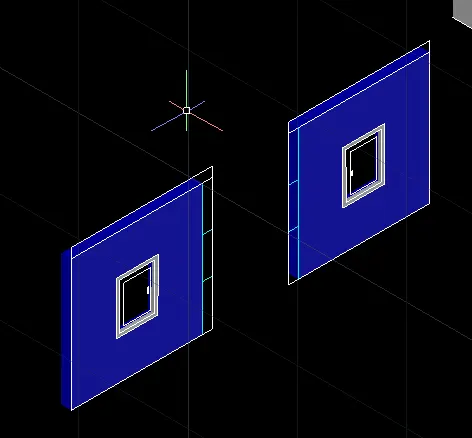
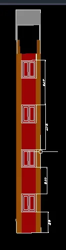
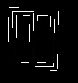
AIM-Create the 3D View of the Building Façade as given in the plan and elevation. Also, see the detail of the window.
PROCEDURE -
Commands Used in this challenge
Line
Rectangle
Trim
Move
Copy
Explode
Circle
Dimlinear
Dimcontinue
Boundary
3Dorbit
3D rotate
Extrude
Region
UCS
Camera
Block
Render RR
Sweep
Create Light
Step 1: Creating Layers
Open Layer properties and create new layers by clicking on new layer or right click on any layer and select new layer to create new layer
Layers are created as follows
Step 2: Creating Layers
Change the current layer to 3D_Wall
Create a rectangle of dimensions at any point on the screen
Offset the rectangle to inside to distance of as wall thickness
Delete the left and bottom lines and extend them to the edges as shown in figure
Step 3: Creating 3D View
Change the view to 3d by clicking on home button of view cube Set UCS as world
Create the boundaries for the walls using ‘BO’ command
Extrude the boundaries created to total height of DIM
Select all the wall and use group command to group then together
Draw rectangles at both windows and change them to boundaries using boundary command
Extrude both rectangles drawn to height of 3’4” as shown in the figure
Draw rectangles at top of both window openings and change them to boundaries using boundary command
Type UCS and click on face and select the face having 3’ wide window Draw a rectangle from bottom part of window with dimensions @3’,4’
Type UCS and click on face and select the face having 3’2” wide window Draw a rectangle from bottom part of window with dimensions @3’2”,4’
Change the ucs back to world
Extrude the rectangle drawn at top side to top edge of window Group all the wall components together
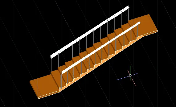
AIM-Create the ismoteric 3d view of a stair with railing as shown in the plan and elevation. Assume the size of the balustrades and the hand rails.
PROCEDURE -
Commands Used in this challenge
Line
Rectangle
Trim
Move
Copy
Explode
Circle
Dimlinear
Dimcontinue
Boundary
3Dorbit
3D rotate
Extrude
Region
UCS
Camera
Block
Render RR
Sweep
Create Light
AIM-Create the ismoteric 3d view of a stair with railing as shown in the plan and elevation. Assume the size of the balustrades and the hand rails.
PROCEDURE -
Commands Used in this challenge
Line
Rectangle
Trim
Move
Copy
Explode
Circle
Dimlinear
Dimcontinue
Boundary
3Dorbit
3D rotate
Extrude
Region
UCS
Camera
Block
Render RR
Sweep
Create Light
Step 1: Creating Layers
Open Layer properties and create new layers by clicking on new layer or right click on any layer and select new layer to create new layer
Layers are created as follows
Step 2: Creating Layers
Change the current layer to 3D_Wall
Create a rectangle of dimensions at any point on the screen
Offset the rectangle to inside to distance of as wall thickness
Delete the left and bottom lines and extend them to the edges as shown in figure
Step 3: Creating 3D View
Change the view to 3d by clicking on home button of view cube Set UCS as world
Create the boundaries for the walls using ‘BO’ command
Extrude the boundaries created to total height of DIM
Select all the wall and use group command to group then together
Draw rectangles at both windows and change them to boundaries using boundary command
Extrude both rectangles drawn to height of 3’4” as shown in the figure
Draw rectangles at top of both window openings and change them to boundaries using boundary command
Type UCS and click on face and select the face having 3’ wide window Draw a rectangle from bottom part of window with dimensions @3’,4’
Type UCS and click on face and select the face having 3’2” wide window Draw a rectangle from bottom part of window with dimensions @3’2”,4’
Change the ucs back to world
Extrude the rectangle drawn at top side to top edge of window Group all the wall components together
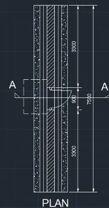
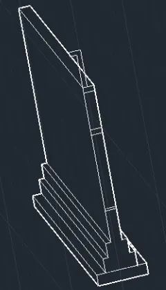
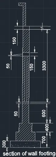
.AIM- Create the 3D view of a Wall with spread footing . Create the Door opening only. Assume the size of the parpaet and the coping. See the plans and elevation for the details. Also, create a rendered view of the model with materials as of your choice.
PROCEDURE -
Commands Used in this challenge
Line
Rectangle
Trim
Move
Copy
Explode
Circle
Dimlinear
Dimcontinue
Boundary
3Dorbit
3D rotate
Extrude
Region
UCS
Camera
Block
Render RR
Sweep
Create Light
Step 1: Creating Layers
Open Layer properties and create new layers by clicking on new layer or right click on any layer and select new layer to create new layer
Layers are created as follows
Step 2: Creating Layers
Change the current layer to 3D_Wall
Create a rectangle of dimensions at any point on the screen
Offset the rectangle to inside to distance of as wall thickness
Delete the left and bottom lines and extend them to the edges as shown in figure
Step 3: Creating 3D View
Change the view to 3d by clicking on home button of view cube Set UCS as world
Create the boundaries for the walls using ‘BO’ command
Extrude the boundaries created to total height of DIM
Select all the wall and use group command to group then together
Draw rectangles at both windows and change them to boundaries using boundary command
Extrude both rectangles drawn to height of 3’4” as shown in the figure
Draw rectangles at top of both window openings and change them to boundaries using boundary command
Type UCS and click on face and select the face having 3’ wide window Draw a rectangle from bottom part of window with dimensions @3’,4’
Type UCS and click on face and select the face having 3’2” wide window Draw a rectangle from bottom part of window with dimensions @3’2”,4’
Change the ucs back to world
Extrude the rectangle drawn at top side to top edge of window Group all the wall components together