Crash-Worthiness for Roof Strength Check on BIW Structure using Hypermesh and Radioss
Aim:
To perform computer model Crashworthiness Crash test for Roof Crush Analysis on the BIW Structure of Automotive Vehicle using HYPER-MESH & RADIOSS and check the roof strength.
Objective:
The objective is to analyze the BIW (Body in White) with the roof crush analysis and check for the impact of this roof crush on the BIW structure in the high-velocity crash.
Study of the forces received energy generated and displacement on the various sections of the BIW and study of the various energy plots after running the simulation.
Abstract:
- Transform the Impactor to the required region as shown below.
fig - Impactor
fig - Reference Model
- Check for the correct interfaces.
- Assign Boundary Condition to Vehicle as well to the Impactor.
- Assign Imposed Displacement to the Impactor to make crush on the vehicle.
- Check for the control cards.
- Create Engine File using Engine keywords.
- Setup the model for required outputs.
- Setup the model for required animations.
- The solution, Result, and Post-Processing.
Introduction:
What is a crash test?
A crash test is a form of destructive testing usually performed to ensure safe design standards in crashworthiness and crash compatibility for various modes of transportation or related systems and components.
Types of Crash Test:
- Frontal-impact tests: Front Impact test is what most people initially think of when asked about a crash test. Vehicles usually impact a solid concrete wall at a specified speed, but these can also be vehicles impacting vehicle tests. SUVs have been singled out in these tests for a while, due to the high ride-height that they often have.
- Moderate Overlap tests: Moderate Overlap tests in which only part of the front of the car impacts with a barrier (vehicle). These are important, as impact forces (approximately) remain the same as with a frontal impact test, but a smaller fraction of the car is required to absorb all of the force.
- Small Overlap tests: Small Overlap tests this is where only a small portion of the car's structure strikes an object such as a pole or a tree, or if a car were to clip another car. This is the most demanding test because it loads the most force onto the structure of the car at any given speed. These are usually conducted at 15-20% of the front vehicle structure.
- Side-impact tests: Side Impact test these forms of accidents have a very significant likelihood of fatality, as cars do not have a significant crumple zone to absorb the impact forces before an occupant is injured.
- Pole-impact tests: A difficult test that places a large amount of force on a small proportion of the side of the vehicle.
- Roll-over tests: A rollover test tests a car's ability (specifically the pillars holding the roof) to support itself in a dynamic impact. More recently, dynamic rollover tests have been proposed in place of static crush testing (video).
- Roadside hardware crash tests: Roadside hardware crash test is used to ensure crash barriers and crash cushions will protect vehicle occupants from roadside hazards, and also ensure that guard rails, signposts, light poles, and similar appurtenances do not pose an undue hazard to vehicle occupants.
- Old versus new: Often an old and big car against a small and new car, or two different generations of the same car model. These tests are performed to show the advancements in crashworthiness.
- Computer model: Because of the cost of full-scale crash tests, engineers often run many simulated crash tests using computer models to refine their vehicle or barrier designs before conducting live tests.
- Sled testing: A cost-effective way of testing components such as airbags and seat belts is conducting sled crash testing. The two most common types of sled systems are reverse-firing sleds that are fired from a standstill, and decelerating sleds which are accelerated from a starting point and stopped in the crash area with a hydraulic ram. It can also be used to evaluate the whiplash protection of a vehicle's seat.
But for our study, we will just see the Roof Crush Test (Roll Over Test) of the BIW Structure. For this, we have the BIW structure available as below.
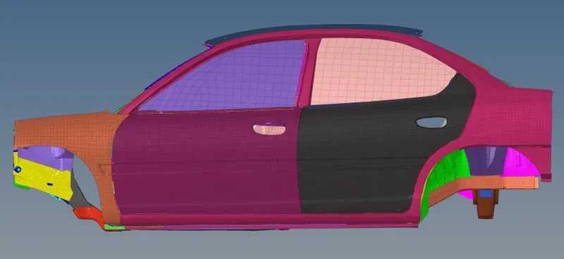
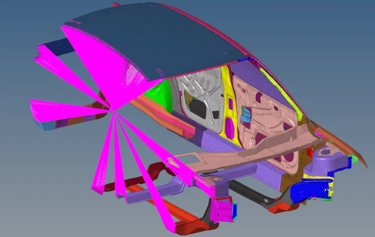
fig - BIW Structure
ROOF CRUSH CRASH-WORTHINESS for passenger vehicles is currently evaluated by the Federal Motor Vehicle Safety Standard (FMVSS) 216 static roof strength compliance test.
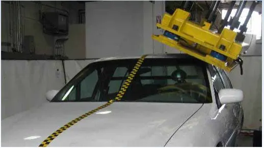
Sample - Roof Crush Test
Model Setting:
Step I - Import the model in the Hypermesh Window
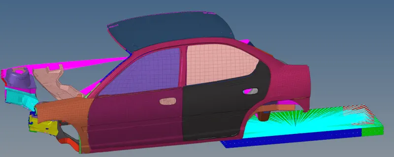
fig - Imported Model for Vehicle and Impactor
After importing the model in the HYPER-MESH the position of the impactor is not at the required location for this the impactor is transformed first to the required region using the below parameters.
• A 180° rotation about the global z-axis with the point opposite to C as a base point
• A 5° rotation about the axis through axis AB
• A 25° rotation about the axis through axis AC
• A translation to put point A at global ( -3500.00, 584.822, 1343.06)
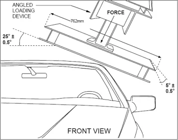
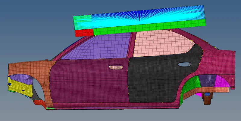
fig - Transformed Position of Impactor
Step II - Interfaces with Penalty Method
The penalty method is one of the contact treatments used in Radioss. Interfaces using the penalty method are based on master/slave treatment. Penalty methods do not ensure kinematic contact continuity, but they add springs at the contact spots.
- /INTER/TYPE7 - Interface TYPE7 is a multi-usage impact interface, modeling contact between a master surface and a group of slave nodes. It is also possible to consider heat transfer and heat friction.
After transforming the Impactor position next step was to define the contact interface between the impactor and the vehicle body. For this, the below parameter was edited after creating the contact group card as shown below
• Created a Type 7 contact interface between the impactor and the car.
• Choose an appropriate stiffness definition - 0.001.
• Choose an appropriate minimum gap of 0.5 mm.
• Assigned the coefficient of friction to 0.2.
• Choose the appropriate friction penalty formulation (I_form = 2).
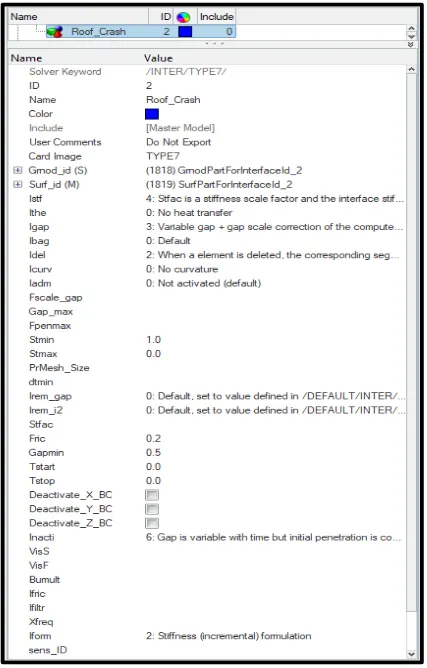
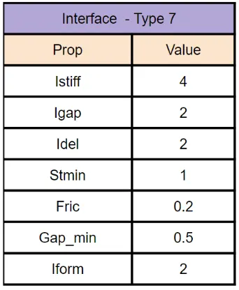
fig - Interface Impactor_Neon Car
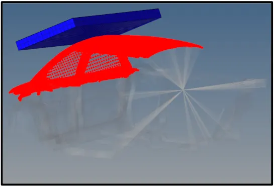
fig - Slave and Master Node Definition
This interface card is created to define the contact between the impactor and the car. Another interface card is created in the same model to define the self impact contact of the car as shown below. The red color nodes are slave nodes and the blue color elements are master nodes in the model.
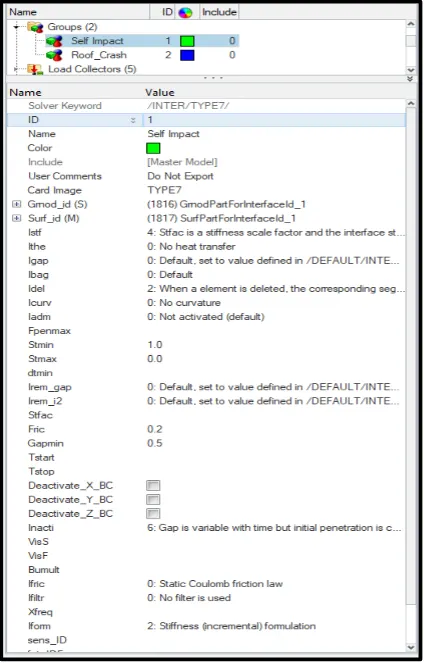
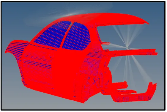
fig - Self Impact Interface Card
This self contact interface card is created to define the contact interface between the component to component self impact in the car model.
Same parameters are passed as of Impactor & Neon Car Interface Card. The red color nodes are slave nodes and the blue color elements are master nodes in the model.
Step III - Kinematic Conditions and Loading
In this group, keywords are used to define the kinematic condition (constrain/release rotation or translation DOF) and initial condition (rotational/translational velocity). Under the Solver Tab, we define the Kinematic using the BCS (Boundary Condition Card)
/BCS - Defines boundary conditions on node groups for translational and rotational motion.
Boundary Conditions for Shock Towers
There are three Shock towers for suspension in the model at 3 different locations. These shock tower nodes should be locked for not to move in the translational z-axis. For this, we provide a rigid body connection to all the nodes of shock towers.
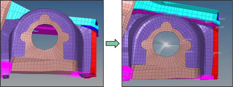
fig - Rigid Body for Shock Towers
After creating the rigid body the translation motion of this rigid body is locked in the Z-axis using the boundary condition as shown below.
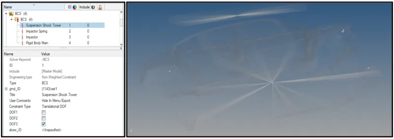
fig - BCS for Z-Axis Locked
Step IV - Boundary Conditions for Impactor
- The impactor assembly contains a spring attached for stability. Created a BCS collector to fix the free end of the spring.
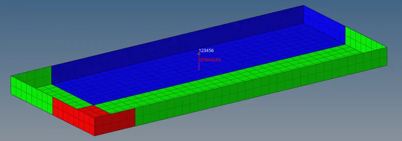
fig - BCS Free End of Spring
- Created a moving SKEW to define the direction normal to the impactor’s face.
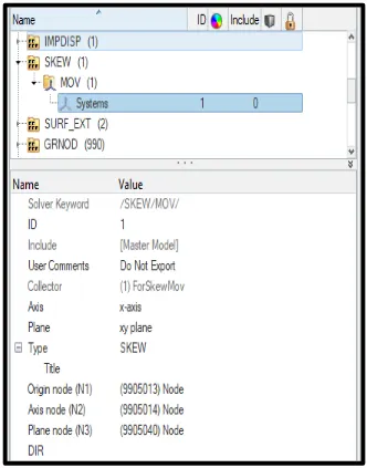
fig - Skew for Impactor
- Created a BCS collector to guide the master node of the impactor rigid body so that it is free to translate normally to the face of the impactor, but is fixed in all other DOFs.
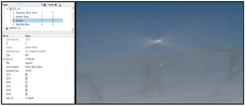
fig - BCS for Master Node of Impactor
The purpose of this BCS is such a way that the impactor will be allowed to move in Z-axis mean it will impact the car and then we can check for the roof strength.
Step V - Imposed Displacement
/IMPDISP - Defines imposed displacements on a group of nodes.
• Imposing the velocity of the impactor starting from 0 mm/s at t = 0. The displacement of the impactor is defined as 200 mm at 200 ms. This means that the impactor will move at 1mm/1ms.
For this, we created the function card and assign the value as,
0 s - 0 mm
200 s - 200 mm
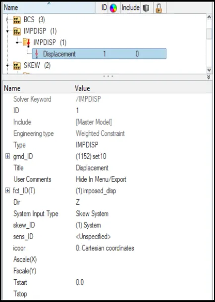
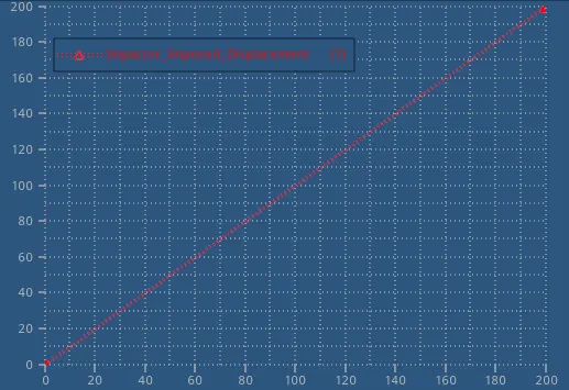
fig - Imposed Displacement
Step VI - Check for Control Cards
• /ANALY card
Defines the type of analysis and sets analysis flags.
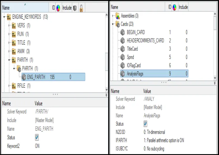
If the parallel arithmetic flag is set ON, the same numerical results will be obtained irrespective of the number of processors used.
This card is read-only once. Only the first card /DEF_SHELL written in the model is used. The other card /DEF_SHELL is ignored.
• /DEF_SHELL card
This keyword is used to set default values for certain parameters in all shell properties, but options could still be changed in each property set input, and in this case, the latter will prevail.
• /DEF_SOLID card
This keyword is used to set default values for certain parameters in all solid properties and thick shells. The default values defined here will be overwritten by any values entered on the individual property input.
This card is read-only once. Only the first card /DEF_SOLID written in the model is used. The other card /DEF_SOLID is ignored.
• /IOFLAG card
Describes the input-output flags.
Run#: Radioss run number (four digits) from 0000 to 9999.
• /SPMD card
Sets SPMD parameters for Hybrid Massively Parallel Program (HMPP) computation.
• /TITLE card
Describes the title.
The title must not start with a forward slash ( / ).
Step VII - Parameters for Engine File
• Use a constant nodal time step.
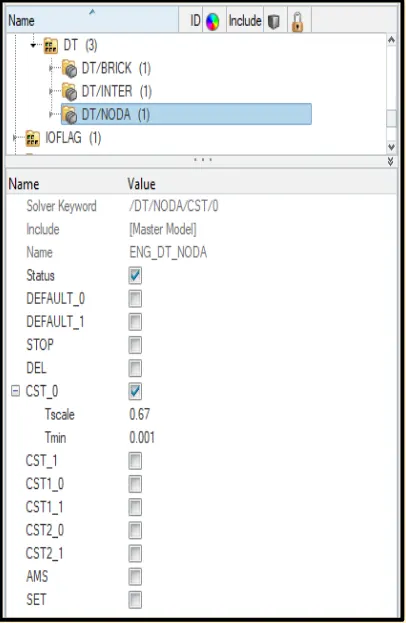
fig - Nodal Time Step
- /DT/NODA/Keyword3/Iflag
- ΔTsca">ΔTsca Δtnodal=√2mkΔTmin">ΔTmin
• Print time history every 0.0001 seconds
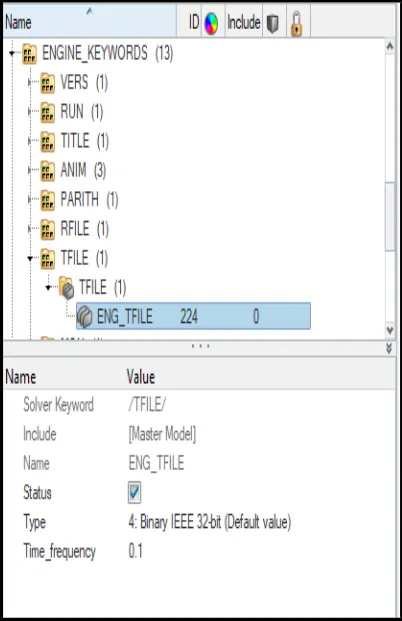
fig - Time History Print
To print the time history for every 0.0001 seconds we input the time_frequency value of 0.1 ms.
/TFILE:
Defines the frequency of writing the time history file of T-file "RunnameTnn".
• Solve for 200 ms
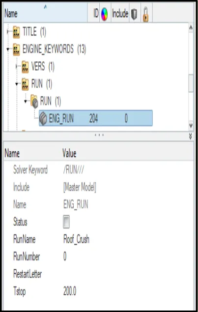
fig - Run Time
Simulation run time is set to 200 ms.
/RUN/ENG_RUN
Identifies the run number.
• Create an animation file every 0.005 seconds
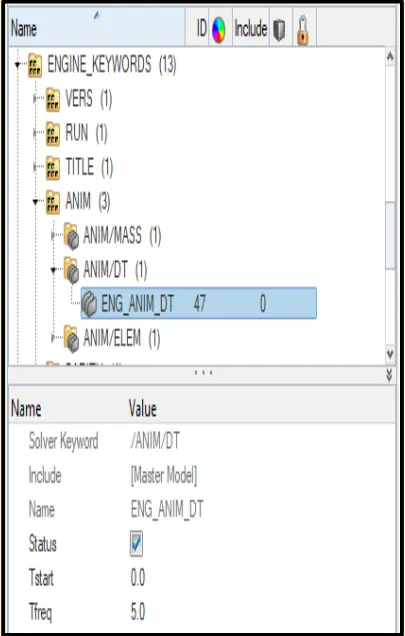
fig - Animation File Creation
The animation has to be created at every 0.005 sec which is equal to 5 ms. For this time-frequency is set to 5.
/ANIM/DT
Write animation files (A-files) at a time-frequency equal to Tfreq, the first file being written at time Tstart. The animation file name will be RunnameAnnn where Runname is the Run Name and nnn is the file number.
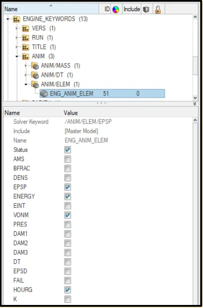
Step VIII - Include selected output in animation files
• Elemental Energy
• Elemental equivalent plastic strain
• Elemental hourglass energy
• Elemental von Mises stress
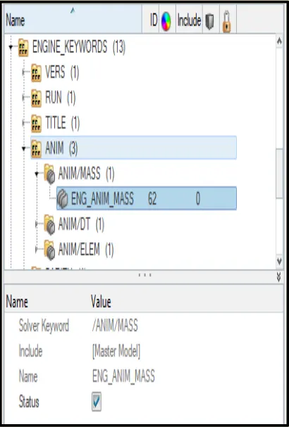
• Nodal added mass
• Turn on parallel arithmetic
Solution and Results Post Processing
• Model is run and now we go for the required results. Before this, we check for the engine file 0001.rad and the energy error through the .out file.
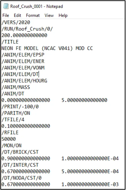
fig - Roof_Crush_0001.rad [Engine File]
Here we can how the engine file is created as per the parameters provided in the Engine Keyword in the solver.
- Runtime
- Title
- Output Animations Requested
- Animation File Creation Timing
- Print File Data
- PARITH_ON Parallel Arithmetic)
- TFILE
- RFILE
- MON
- DT/NODA/CST
- DT/BRICK/CST
Total Simulation Time
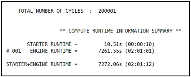
The whole simulation completed in 7272.06s(2:01:12). The total number of cycles run during this time is 200001 no.
.Out-File
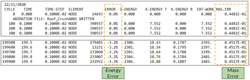
Simulation is started with 0% energy error and mass error of 0.0048. At the end of the simulation, the energy error is found to be -3.3% which is within the acceptable range. So the next step is how the near car behaved throughout the simulation. For this, we check for the h3id file the results are here below.
Elemental Energy
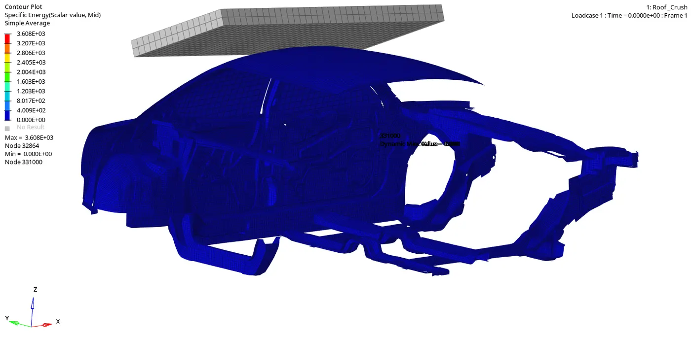
fig - Elemental Specific Energy
The total elemental energy generated during the run is 3608 mJ.
Equivalent Platic Strain
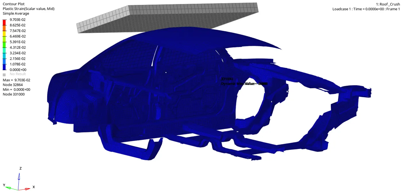
fig -Equivalent Plastic Strain
The total plastic strain generated in the neon car during the run is 0.097.
Elemental Hourglass Energy
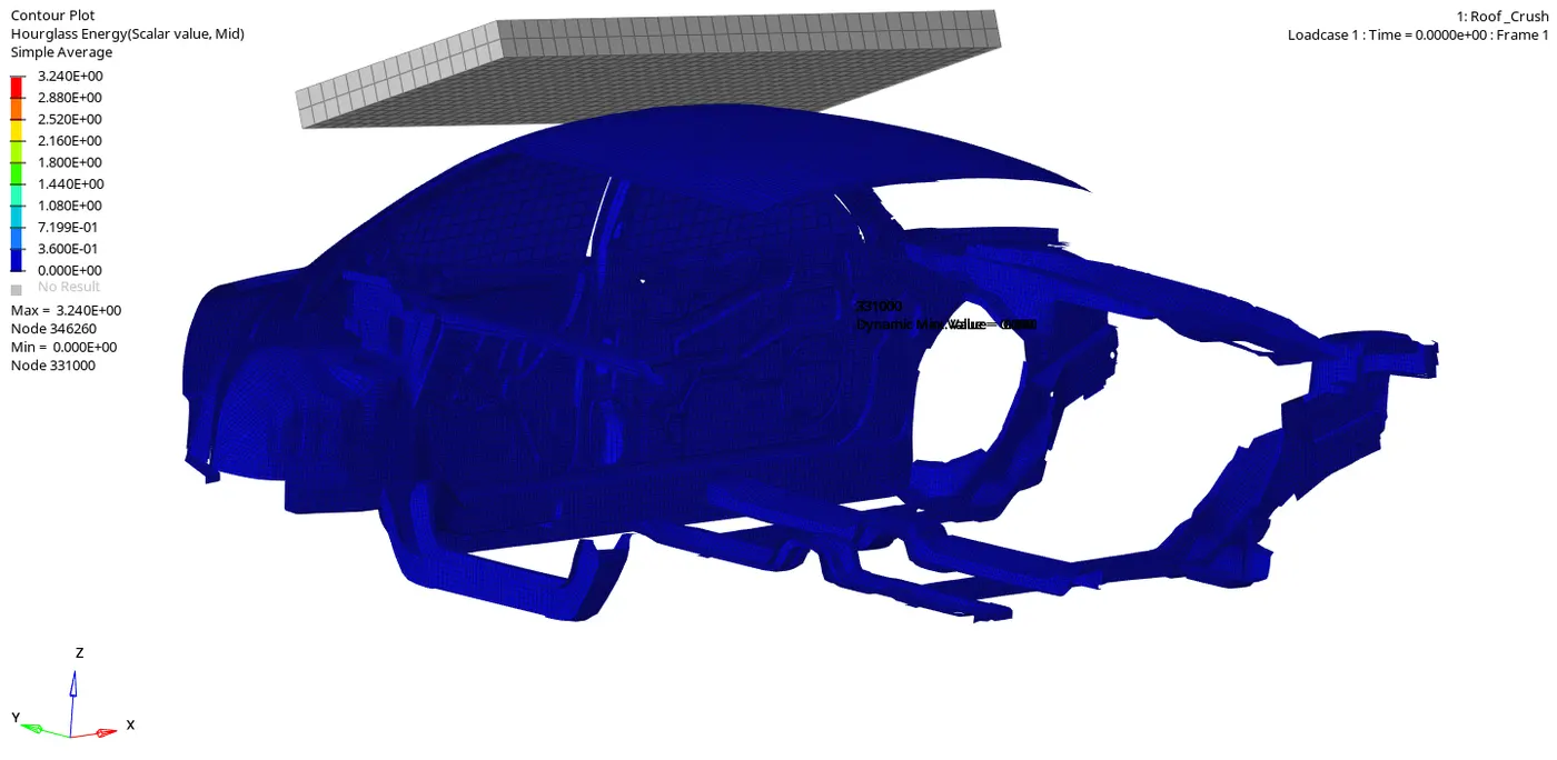
fig -Elemental Hourglass Energy
The total hourglass energy recorded during the runtime is 3.24 mJ.
Von Mises
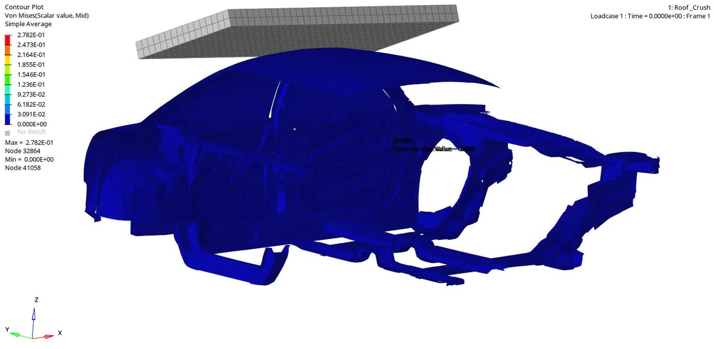
fig - Von-Mises Stress
The total von-mises stress recorded in the neon car model during the roof crush is 0.278 kN/mm^2.
Elemental Time Step and Displacement
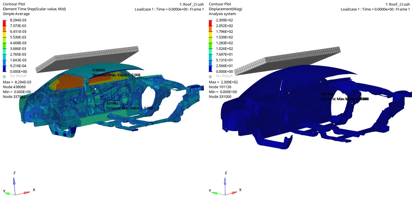
fig - Elemental Time Step and Displacement
The total displacement recorded in the BIW structure during the runtime is 230 mm.
Nodal Displacement
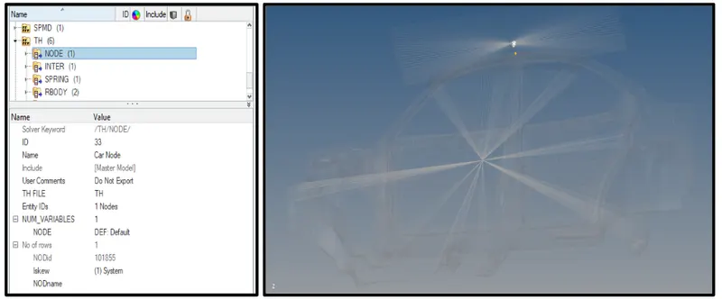
The nodal displacement of the node is measured at node number 101855.
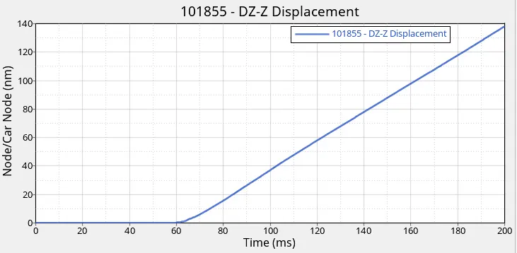
fig - Node 101855 Displacement
From the above graph, we can see that till 60 ms their curve is flat with no displacement value recorded due to no contact between the impactor and the neon car. After 60 ms as soon as the impactor comes in contact with node 101855 there starts the change in the displacement of the model till the end of runtime.
Plotting Force vs. Displacement
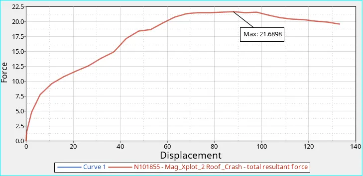
fig - Force vs. Displacement
Check for the FMVSS 216 Roof Strength
From the above graph, we have a resistance force value recorded as 21.69 kN (21689 N) on the roof of the car. As per the FMVSS, the car roof should be able to withstand the force of 47000N.
According to FMVSS. Specified strength to weight ratio required a resistance force of 3 times the GVW to withstand the roof crash
In our case, the total weight of the car is 174 Kg. So total resistance force will be,
Resistance Force = 3*9.81*174 = 5120.82 N
From the above figure, we can conclude that the mass of the vehcile is not enough to resist the impactor force of 21689 N which is not equal to 5120.82 N (not matching). So to make the car roof withstand this impactor force we have to add the mass to the vehicle body to make it more durable and stable during the roof crash.
Energy vs Time Curve
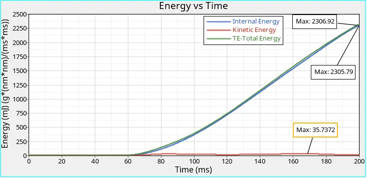
fig - Energy vs Time Curve
The kinetic energy should start as the simulation start but as the impactor is impacting the top surface of the roof after 60 ms the kinetic energy started recording in the plot. The maximum value reached by the kinetic energy till the end of the simulation is 35.73 mJ.
As per the general rule, for the analysis to be quasi-static the kinetic energy should be 5% of the total internal energy.
The total internal energy recorded in this simulation is 2306 mJ by the end of the simulation.
5% of this is 115.25 mJ so we can say that this is not the case of quasi-static analysis.
The total energy during the run is recorded to be 2606 mJ.
The total energy should be equal to the external work but in this simulation, there is some energy loss due to the contact energy.
Contact Energy vs Hourglass Energy
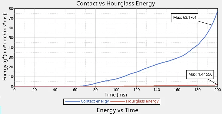
Here the hourglass energy recorded is 1.44 mJ which is comparatively quite low and negligible. The contact energy is varying exponentially during the simulation which is leading to the loss of the total energy.
Learning Outcome -
1] CRASH-WORTHINESS setup for Roof Crush in FEA.
2] Error rectifying in the Roof Crush Model Checker in FEA.
Conclusion -
As the purpose of this project is to check the roof strength of the car we can conclude that the vehcile resistance force is not enough to withstand the standard force of FMVSS. To make the car more durable and stable we have to think the various approach
By changing the thickness of the roof of the car to withstand the rollover forces.
Another approach can be changing the material of the roof to make it stiffer.
Change the material of the other supporting member can also help a lot.