Conjugate heat transfer analysis on a graphics card (electronic part cooling) using ANSYS fluent
Aim:-> Conjugate heat transfer analysis on graphic card using ANSYS Fluent.
Theory:
Conjugate heat transfer (CHT) is a type of simulation where it allows heat transfer between fluid and solid domain by exchanging thermal energy at contact surface. Here heat is exchanged at interfaces and transported by conduction process in solid and additionally by convection process within fluid. The CHT approach has an advantage over Finite element thermal analysis in that wall heat transfer coefficients and their local variations on surfaces are directly calculated within the model rather than based on simplified empirical calculations. The CHT approach therefore has benefits for those applications where heat transfer is either non-uniform or difficult to calculate empirically.
Graphics card is a type of display adapter or video card installed within most computing devices to display graphical data with high clarity, color, definition and overall appearance. Graphics card provides high-quality visual display by processing and executing graphical data using advanced graphical techniques, features and functions. Graphics card is also known as a graphics adapter, graphics controller, graphics accelerator card or graphics board.

Graphics card is primarily designed to remove the graphical processing tasks from the processor or RAM. It includes a dedicated graphical processing unit (GPU) and a dedicated RAM that help it to process graphical data quickly. Like most processors, a graphics card also has a dedicated heat sink to keep the heat out of the GPU. A graphics card enables the display of 3-D images, image rasterization, higher pixel ration, a broader range of colors and more. A graphics card can be integrated within the motherboard or be added on as an extension card.
Graphic card generally includes following elements
- Processor
- Fins
- Base
Geometry:
The geometry is prepared in ANSYS space-claim. Enclosure is provided for simulation. In following diagram inlet and outlet is shown using legends.

Fig: Geometry setup
In this project heat is transfer from processor to fins and base via conduction first and then the heat is transferred to air via forced convection. The heat generating source is processor in graphic card. Through some research papers it is concluded that almost 99.9% of energy consumed by processor is given out in form of heat.
The air is introduced from inlet with different inlet velocities between 1m/s to 5m/s. The air flows in negative X-axis over the graphic card. As air with temperature 300K get in contact with hot graphic card elements, the heat from those elements started to transfer due to convection and component's temperature lowers down, hence electronic components cooling is performed.
Meshing:-
| Baseline mesh | Refined mesh | ||
| Number of nodes | Number of elements | Number of nodes | Number of elements |
| 15630 | 83013 | 75394 | 415930 |
| Table 1: Mesh count | |||
For baseline mesh we have taken default mesh size for every parts and didn't provided any refinement to parts. For finer mesh condition we have provided some local refinement and this condition gives us 415930 elements, after reducing mesh size further we obtain more than half million elements, which is impossible to solve due to computational power and student license restrictions.
Hence for fined mesh condition which we have choose, mesh size is as follows,
Overall body mesh size= 3mm
Mesh size for fin body = 0.5mm
Mesh size for processor body = 0.5mm
Mesh size for base = 0.5mm
| Baseline mesh | Refined mesh |
 |
 |
| Fig: Meshing of processor and base | |
 |
 |
| Fig: Meshing of fins base plate | |
 |
 |
| Fig: Overall meshed geometry | |
 |
 |
| Fig: Meshing quality matrix | |
 |
 |
| Fig: Meshing quality matrix | |
Material properties:-
In general the material used for processor is Silicon, for base is Steel and for fins is Aluminum.
| Component | Material | Density (kg/m^3) | Specific heat (J/kg-k) | Thermal conductivity (W/m-k) |
| Processor | Silicon (Si) | 2000 | 710 | 150 |
| Base | Steel | 8030 | 502.48 | 17 |
| Fin | Aluminum (Al) | 2719 | 871 | 180 |
| Enclosure | Air | 1.225 | 1006.43 | 0.0242 |
| Table 2: Material properties | ||||
Boundary conditions and setup:
- Inlet air temperature = 300K
- Inlet air velocity = 1m/s, 3m/s & 5m/s
- Pressure at outlet = 1atm pressure
By referring some websites, the heat generated in graphic card processor is around 1e8 to 1e10 W/m^3. So it is assumed for our project that Heat generated from processor = 1e9 W/m^3. So we have provided source term to processor through cell zone option.
We have used steady state pressure based solver with energy and `k-omega` viscous turbulence model.
~Case A: For Velocity 1m/s
| Baseline mesh | Refine mesh |
|
|
|
| Fig: Temperature on base surface | |
 |
|
| Fig: Wall conjugate heat transfer coefficient | |
|
|
 |
| Fig: Temperature on Fin surface | |
 |
|
| Fig: Conjugate heat transfer coefficient on processor wall | |
 |
|
| Fig: Temperature on processor surface | |
 |
|
| Fig: Temperature contour | |
 |
|
| Fig: Velocity contour | |
 |
|
| Fig: Velocity vectors | |
 |
|
| Fig: Temperature - volume rendering | |
 |
|
| Fig: Residual plot | |


By comparing above pictures we obtained better result from refined mesh, so let us go with refined mesh for further simulation cases.
~Case B: Velocity 3m/s

Fig: Residual plot

Fig: Temperature on base surface

Fig: Wall conjugate heat transfer coefficient

Fig: Conjugate heat transfer coefficient on processor wall

Fig: Temperature on fin surface

Fig: Temperature on processor surface
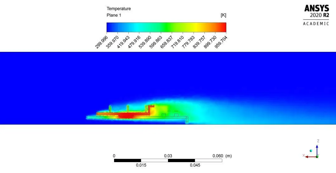 Fig: Temperature contour
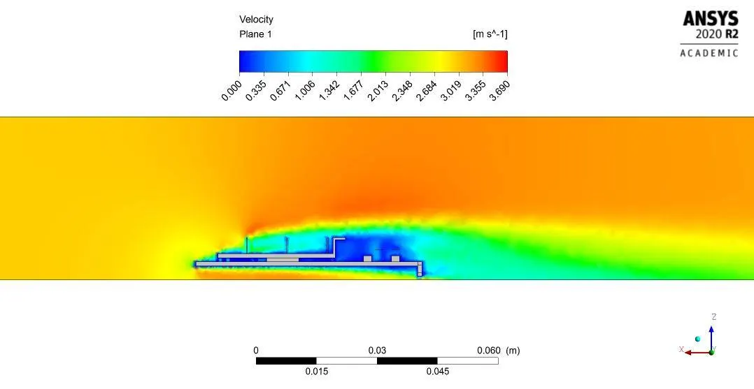 Fig: Velocity contour

Fig: Velocity vector
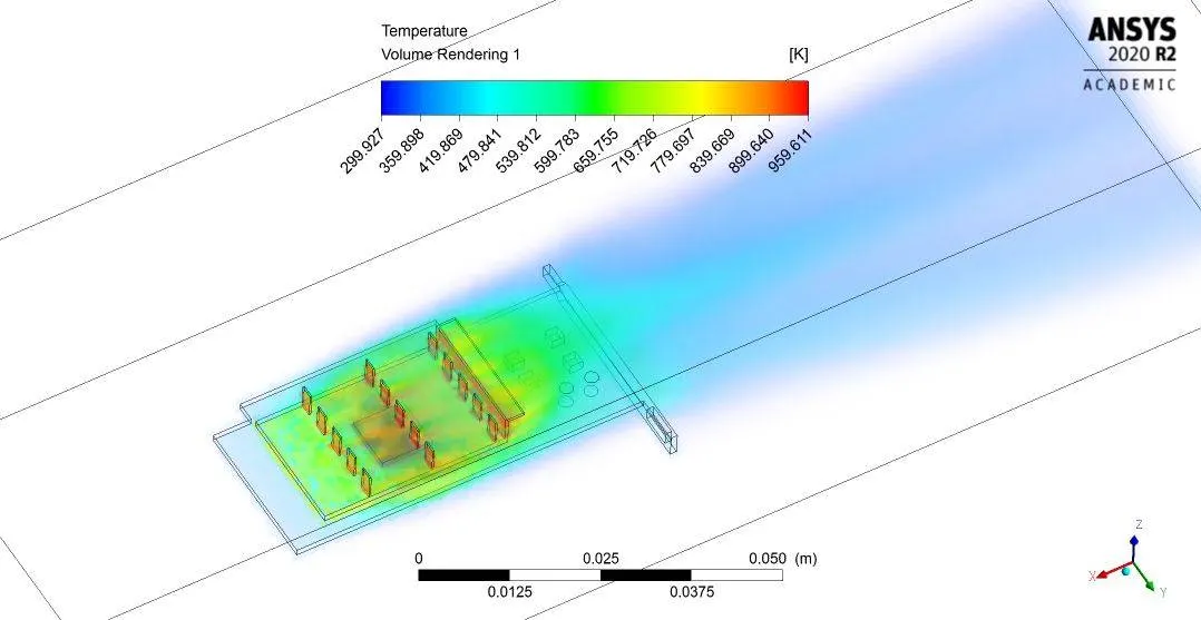 Fig: Volume rendering of temperature
~Case C: Velocity 5m/s

Fig: Residual plot

Fig: Temperature on base surface

Fig: Wall conjugate heat transfer coefficient

Fig: Conjugate heat transfer coefficient on processor wall

Fig: Temperature on fin surface

Fig: Temperature on processor surface
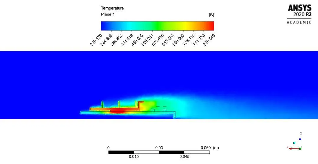 Fig: Temperature contour
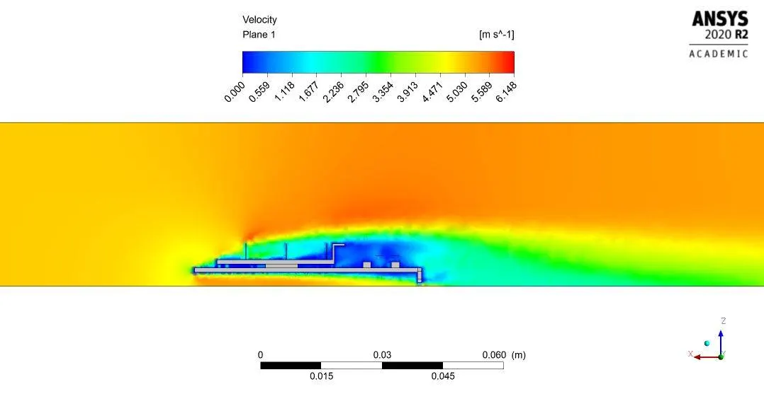 Fig: Velocity contour

Fig: Velocity vector
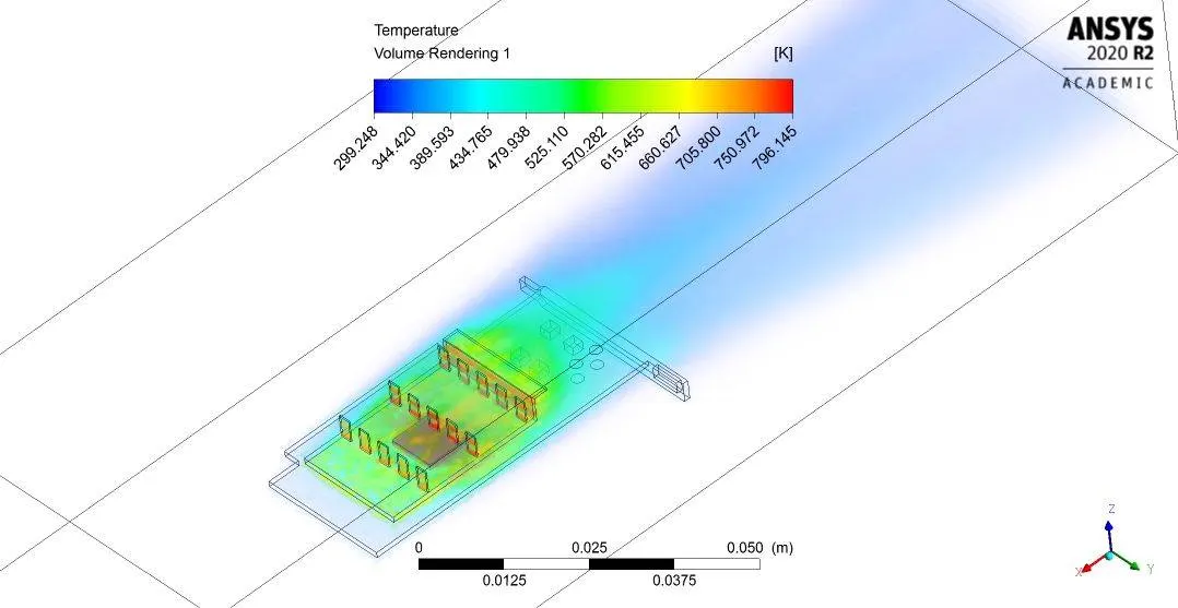 Fig: Volume rendering of temperature
Observe all above figures which shows temperature distributions, in those figures red color zone shows hotspot.
As seen in above all residual plots, the sampe pattern is repeating which shows the solution is converged.
Result:
| Cases (Velocity) | Units | 1 m/s | 3 m/s | 5 m/s |
| Max temperature of processor | (k) | 1535.664 | 958.501 | 795.030 |
| Min temperature of processor | (k) | 1512.279 | 935.824 | 772.758 |
| Max conjugate heat transfer coefficient at processor wall | (W/m^2 - k) | 653.384 | 653.91 | 655.861 |
| Max temperature of fin | (k) | 1537.591 | 956.674 | 793.210 |
| Min temperature of fin | (k) | 1453.874 | 877.008 | 716.201 |
| Max temperature of base | (k) | 1537.613 | 957.003 | 793.485 |
| Min temperature of base | (k) | 627.514 | 398.727 | 355.473 |
| Maximum velocity attained by air @ plane 1 | (m/s) | 1.232 | 3.69 | 6.148 |
| Maximum temperature @ plane 1 | (k) | 1540.5 | 959.704 | 796.549 |
| Table 3: Result parameters for different velocity cases | ||||
Conclusion: By observing all of the above postprocessed figures, tables and data we can conclude that-
- Refined mesh improves wall heat transfer coefficient.
- For refined meshing setting computational memory and time consumed by simulation is more.
- In case of refined mesh, it is possible to capture hotspot zone perfectly.
- To get more accurate results, model needs to be refined further.
- With increase in inlet velocity of air, body temperature of components decreases.
- Due to recirculation of air at rear face of fins, temperature is lower than front face of fin.
- For fast and better cooling the components, air velocity must be greater.
- With increase in velocity, max conjugate heat transfer coefficient at processor wall increases slightly.