Conjugate Heat Transfer Analysis on a graphics card.
AIM:-
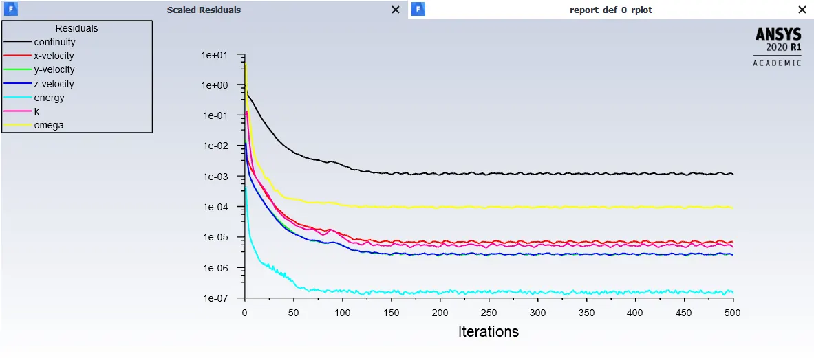
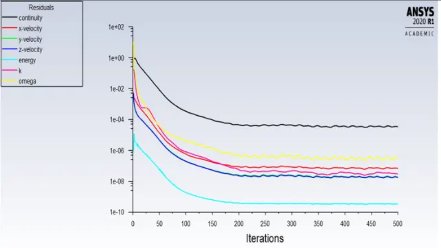
To conduct a CHT Analysis on a Graphics Card and to calculate the wall to surface heat transfer Co-efficient and to justify the solution is converged for 3 different inlet velocity.
INTRODUCTION:-
Conjugate heat transfer analysis(CHT) can accurately predict heat transfer by simultaneous solving all the relevant solid and flow field heat transfer processes, For Instance, it can predict conduction through solids, free and forced convection in the gases/fluids, and thermal radiation. The term conjugate heat transfer is used to describe processes which involve variations of temperature within solids and fluids, due to thermal interaction between the solids and fluids.
THEORY:
ANSYS CFD solvers are based on the finite volume method,
- The domain is discretized into a finite set of control volume.
- General conservation equations for mass, momentum, energy, species, etc. are solved on this set of control volumes.
- Partial differential equations are discretized into a system of algebraic equations.
- All algebraic equations are then solved numerically to render the solution field.
Initially, the process involves three major Categories,
Pre-Processing
- Geometry
- Mesh
- Physics
- Solver Settings
Solve
- Compute solution.
Post Processing
- Examine results.
Geometry:-
- The following Geometry is imported into the spaceclaim.
- Then Each individual part is separated into diffrent components.
- Then Enabling the share topology tool we shared the boundaries with diffrent parts to get a perfect meshing.
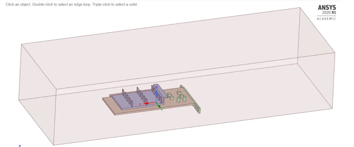
Basic Geometry of the Graphics card with Enclosure
Meshing:-
- Initially, we are going to name various components of the Graphics accordingly to set proper values to it.
- Then for the baseline mesh we are going to be using the default size option.
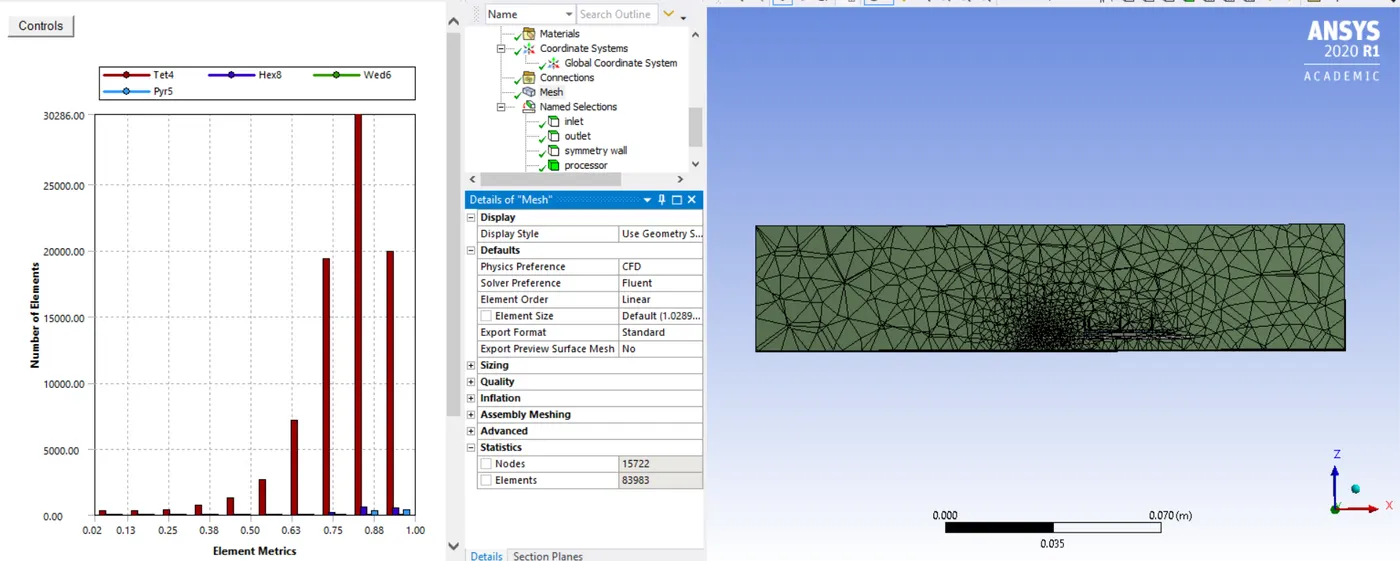
Baseline Mesh
- For Refined mesh we are going to reduce the element size for various parts accordingly as follows.
- Base - 3mm.
- Processor - 0.5mm.
- Components - 0.5 mm.
- Fins - 0.5 mm.
- Enclosure -3 mm.
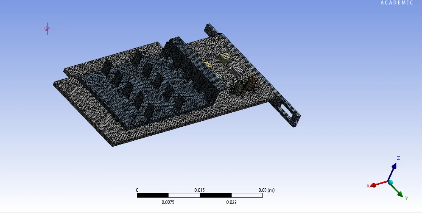
Refined Mesh on the Graphics Card
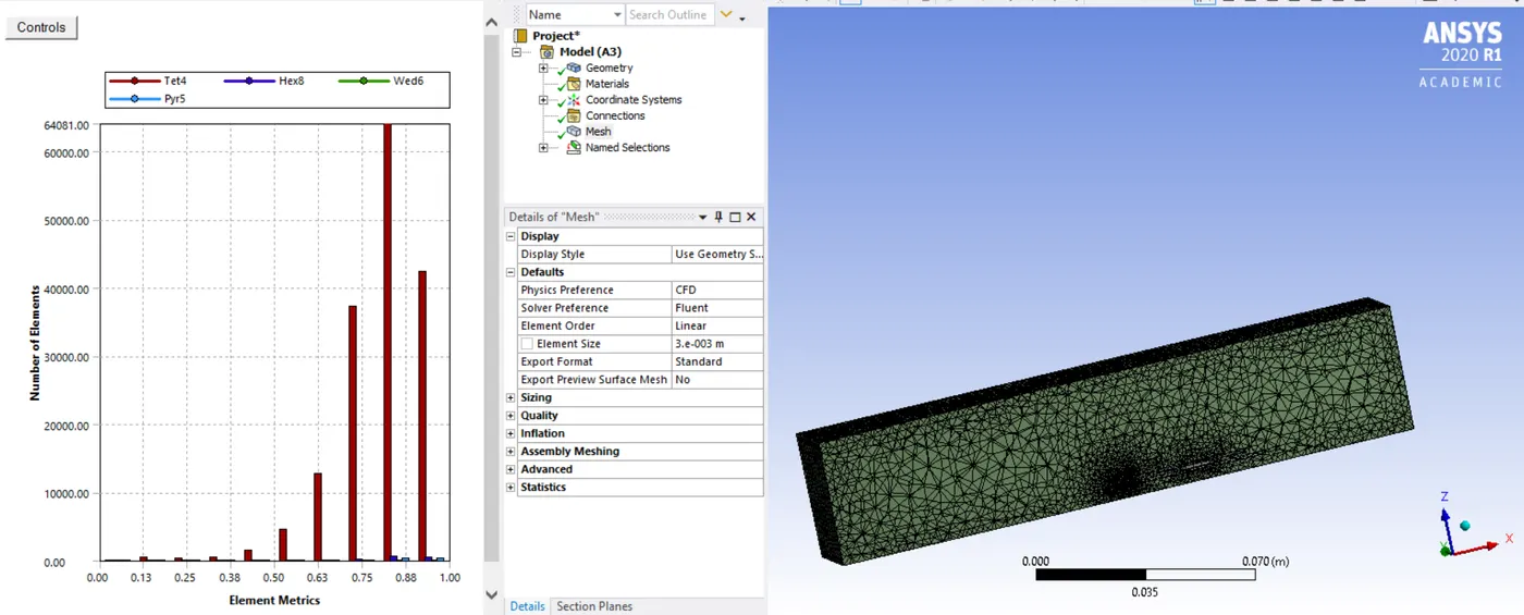
Refined Mesh Section View
Setup:-
- We are going to use Pressure Based solver.
- Under Steady state conditions.
- Having selected the Energy equation and selecting the K Omega SST model.
- In terms of Heat Generation by the processor in Graphics card is given as 93750000w/m 3.
Simulation:-
case 1:-(Baseline Simulation with inlet velocity at 1 m/s)
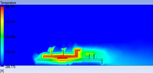
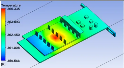
Heat Transfer Coefficient Hotspot
- From simulation, we could infer that there is concentrated heat at the center where the processor is placed.
case 2:-(Refined Simulation with inlet velocity at 1 m/s)
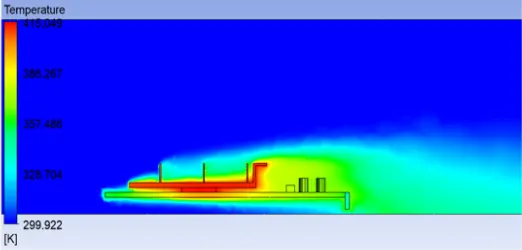
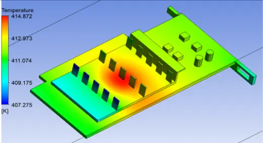
case 3:-(Refined Simulation with inlet velocity at 3 m/s)
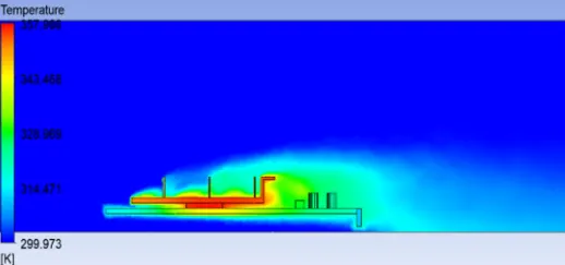
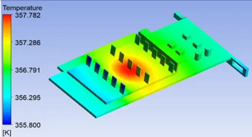
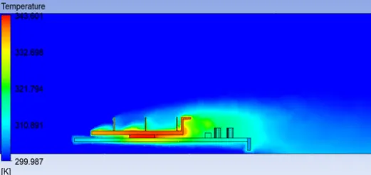
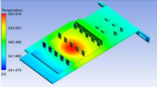
case 4:-(Refined Simulation with inlet velocity at 5 m/s)
Results:-
- Inferring from the following results we could conclude that hotspot is found near the processor of the Graphics card.
- The maximum temperatures attained by various velocities are tabulated below.
| Inlet Velocity | Maximum temperature attained |
| 1 m/s | 416.56 K |
| 3 m/s | 356.94 K |
| 5 m/s | 342.82 K |