Conjugate Heat Transfer Analysis on a graphics card.
CHT Analysis on Graphics Card
Objective:
To perform steady-state conjugate heat transfer analysis on a model of a graphics card by attaining best possible mesh with combination of coarse and refined mesh in different regions.
General Theory: CHT analysis is used where both heat transfer is taking place by conduction and convection,it allows to simulate the heat transfer/exchange between solid and fluid zones by exchanging thermal energy at the interface between them, CHT analysis on graphics card is one of the prominent applications where results achieved are more realistic.
Space claim model:
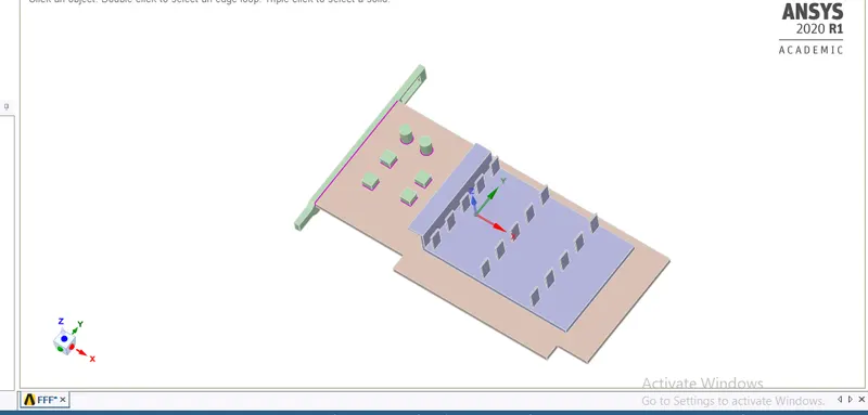
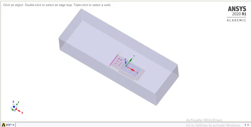
The above model is divided in to three main components :
1) Base including capacitors on it.
2)Processor
3)Fins
4) Enclosure which is a rectangular box around the graphics card,
Mesh model:
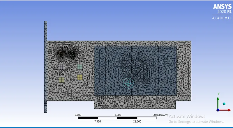
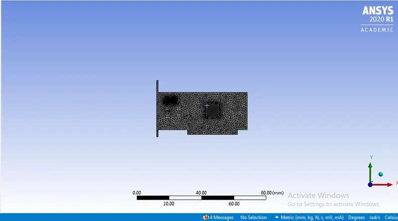
The above mesh is a combination of coarse and fine elements according to the requirement and setup,the main hotspot in the model is processor component as it is the source of heat generation thus elements are more fine in that region and little coarser comparatively in other regions.
Body Sizing methods have been used for refining the regions
1) Body sizing for base ,element size-1mm,
2)Body sizing for fins ,element size-1mm,
3)Body sizing for processor ,element size-0.5mm,
Edge sizing is employed to refine circular capacitors on the base,and no.of divisions method is used-30 divisions.
Elements type-Traingular
Total number of elements-446787.
Fluent Setup:
Solver: Steady state
Solution method:
pressure-velocity coupling -coupled,
Gradient -least squares cell Based,
pressure-second order,
momentum-second order upwind,
Turbulant kinetic energy-first oreder upwind,
Specific Dissipation rate-first order upwind.
As whole project is based on temperature ,Energy module is turned on and viscous model k-`omega`is used though our flow is a laminar , if there are any turbulant zones then effects in those regions will be captured accurately.
Appropriate materials are used in accordance with actual graphics card,
Base -copper
Fins-Aluminum
Processor-silicon (solid)
Boundary conditions-
inlet -velocity inlet (1 m/s, 3m/s, 5m/s) for three different simulations respectively.
outlet -pressure outlet
symmetry for three walls other than base
wall -for base wall ,to capture boundary layer effects if any.
interior for other interior components
Cell zones:
Fluid zones -for enclosure
solid zones-base,fins,processor
source term is enabled and given a constant value in processor zone,
Q =78125000 `W/m^3`
Standard initialization is used as we are initializing solution from inlet .
Solution: vel -1 m/s Vel-3 m/s
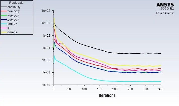
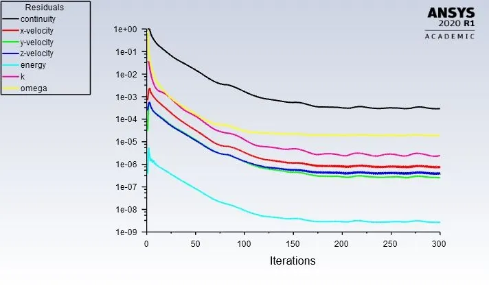
The above residuals shows thet solution has converged,as energy equation is flat after 200 iterations, and other equations are showing same pattern more or less flat.
Velocity -5 m/s
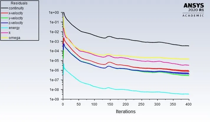
Though the above residual equations seems to be not converged but temperatures on the graphics card got stable at 150th iteration, hence assumed that solution is converged.
Results:
Velocity -1 m/s
Temperature contour
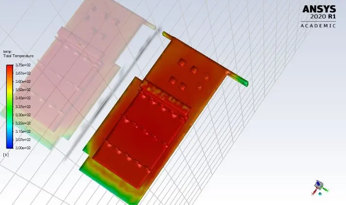
Maximum temperature attained by the graphics card at processor zone is 367.412 k which is an average temperature on the processor measured at 5 different points on the processor.
Calculation of Heat transfer coefficient:
`Q=h*A*dT`
`Q=h1*A*(T_1-T_2)`
In the above equation Q is constant, Area A , and T_2 is constant which is ambient temperature 300k
`5=h1*64*10^-6 *(367.412-300)`
`h_1=1158.91 W/(m^2k)`
Velocity -3 m/s:
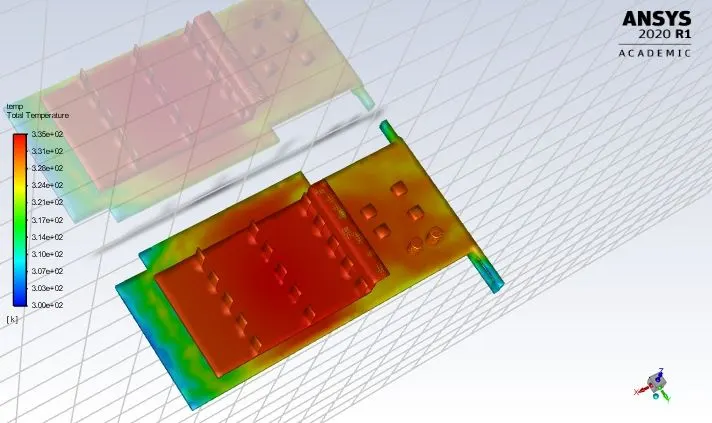
Maximum temperature attained by the graphics card at processor zone is 335 k which is an average temperature on the processor measured at 5 different points on the processor.
Calculation of Heat transfer coefficient:
`Q=h*A*dT`
`Q=h1*A*(T_1-T_2)`
In the above equation Q is constant, Area A , and T_2 is constant which is ambient temperature 300k
`5=h1*64*10^-6 *(335-300)`
`h_2= 2232.14W/(m^2k)`
Velocity -5 m/s:
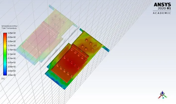
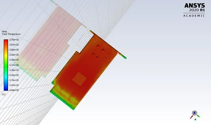
Maximum temperature attained by the graphics card at processor zone is 323.35 k which is an average temperature on the processor measured at 5 different points on the processor.
Calculation of Heat transfer coefficient:
`Q=h*A*dT`
`Q=h1*A*(T_1-T_2)`
In the above equation Q is constant, Area A , and T_2 is constant which is ambient temperature 300k
`5=h1*64*10^-6 *(323.35-300)`
`h_1=3341.53 W/(m^2k)`
| S.No | Velocity m/s | Max.Temperture k | Heat Transfer Coefficient w/m^2k |
| 1 | 1 | 367.412 | 1158.91 |
| 2 | 3 | 335 | 2232.14 |
| 3 | 5 | 323.38 | 3341.53 |
From the above table , it is clear that by increasing the velocity maximum temperature on the graphics card decreasing and heat transfer coefficient increasing.
Velocity is directly proportiional to reynolds number and reynolds number is proportional to Heat transfer coefficient.
From the above contours heat concentrated zones are processor and fins so temperature is high in fins region than in the copper regions though both are contact to processor directly,but fins are made of aluminium and it has thermal conductivity less than copper which is the reason for high temperatures and has high suraface area designed to dissipate more heat than base.