Conceptual design of a building with columns and shear walls
Question 1:
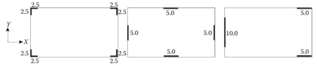
The building shown, 20 × 35 m in plan, has columns on a 5 × 5 m grid and shear walls (with dimensions shown in m, 250 mm in thickness) in three alternative arrangements, (a), (b), (c), all with the same total cross-sectional area of the shear walls. Compare the three alternatives, taking into account the restraint of floor shrinkage, the lateral stiffness and the torsional one with respect to the vertical axis, the vertical reinforcement required for the same total flexural capacity at the base, the static eccentricity, the system’s redundancy, foundation systems, architectural constraints etc.
Design codes define wall as vertical elements with an elongated cross section. A lower limit of 4 for aspect ratio of a rectangular cross section
is used for certical element to be considered as well.
When the shear walls are situated in advantageous position in the building, they can form an efficient lateral force resisting system by reducing
lateral displacements under earthquake loads.
If the cross section consists of rectangular parts, one of which the aspect ratio greater than 4, the element also classified as wall.
As the structure is more restrained it will be more shrinking, expanding and cracking.
There will be more floor shrinkage and expanding in structure A whreas there will be minimum cracks in structure B and C.
Proper placing of shear walls is necessary in earthquake resistant building.
In this Image, structure A nad B is feasible and advantageous beacause the shear walls are symmetrically located.
Shear walls with height to length ration is freater than 1.0 are included in the redudancy consideartion to help ensure that an adquate number of
walls elements is included or that the proper redudancy factor is applied.
Structures A and B are redudant structure compared to structure C.
Failure of structure C will occure first in all aspects.
Question 2:
Discuss the suitability for earthquake resistance of the moment resisting framing plan of a three-storey building depicted here (cross-sectional dimensions in cm), the eccentricity of the centre of mass (as centroid of floor plan) to the centre of stiffness (from the moments of inertia of the columns) are shown. Suggest an alternative. Also, is there torsional flexibility? Are the two fundamental translational modes of vibration larger than the fundamental torsional mode of vibration. Discuss qualitatively.
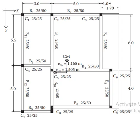
This structural frame has two way eeccentricity of the centre of mass in relation to the centre of stiffnes with the eccentricity of the x direction
being greater than the eccentricity of the Y direction.
Beacause the beams in this building are stronger than the columns, it can be considered a weak column strong beam design in nature.
There is only two continuous frames in the structure that is B1 and B2 in the x direction, and B9,B10 and B11,B12 in the Y direction and all others
beams are broken at the midway in the frame.
There will be torsional flexibility in the structure. To avoid torsional restraints it is better to make the room dimensions even in the both X and Y
direction and placing the column at the junction of thw two wall if it is feasible better to provide shear wall at appropriate location.
Beams with low span to depth ratio have to be dimensioned for high shear forces, from the seismic analysis or from capacity design in shear.
Unless diagonally reinforced, short beams have low deformation capacity and poor ductility.
For the reasons featiled above, short beam spans should be avoided, while spans of 4 to 6 m should be preffered over longer ones, at least
for the storey heights and gravity loads commonly encountered in buildings.
Question 3:
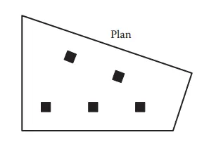
A multi-storey building with basement, with a quadrilateral (non symmetrical floor plan) plan as, has interior columns in an irregular (not in a grid) pattern in plan that serves architectural and functional considerations. Partition walls and interior beams supporting the slab have different layout in different stories. However, there is no constraint to the type, location and size of the lateral force resisting components and sub-systems on the perimeter. Proposals are to be made and justified for the choice of the lateral-load-resisting system and its foundation.
The general layout and certain details of the geometry of an individual frame have a major impact on its seismic behaviour, very important
also is the overall layout of the frames in a structural sysetm.
The location of frames in plan and their span lengths are normally governed by architectural and functional considered, while beam depth may
be controlled by design for factored gravity/ seismic loads.
Never the less, the structural design is essentially free to choose the all important geometric details of individual plane frames and has certain
freedom concering their overall geometry and loaction in plan.
Frames place few constraints on a building architectural design, including the facade and parking space in ground floor.
Earthquake resistance requirements on frames lead to large columns, interaring with architectural functions.
The reinforcement detailing on frames for ductility requires workmanship for high level of its execution and good supervision on site.
Walls seem to have better balance of advantage against drawback neverthless, a concret building always has beams and column to support
the gravity loads, it is the waste not to use them for earthquake resistance.
Therefore frames and walls may well be cost effectively combined a single lateral load resisting system.