Concept on positioning of Columns
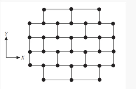
Q.1: - Comment on the layout of the framing plan concerning earthquake resistance in the two horizontal directions X or Y (dots are columns, lines depict beams). Look into aspects of symmetry, redundancy and bi-directional stiffness and ductility.
Answer: -
(a) Symmetry:
(i) Symmetry in the X-direction:
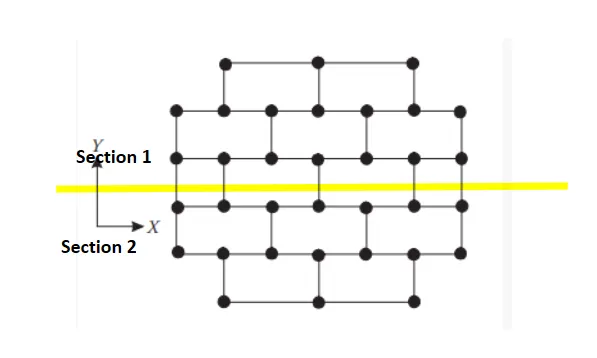
- If we see carefully into the above given plan and split it into two equal portions in the horizontal direction then we can tell just by seeing the above plan that the plan looks mirrored, if we split the given above plan into equal parts.
- This will conclude that the given above plan in the X-direction is symmetric.
(ii) Symmetry in the Y-direction:
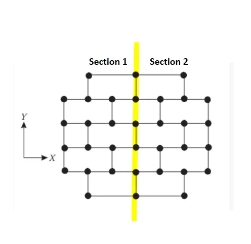
- If we see carefully at the given above plan and then if we will cut the given plan from the middle or we can say that if we split the plan into two equal parts in the Y-direction horizontally i.e., Section 1 and Section 2 as we can see in the above plan then we will be able to understand that the give above plan looked mirrored in the give plan after we split them into two.
- So here we can conclude that the given above plan in the Y-direction is also symmetric.
Result: -
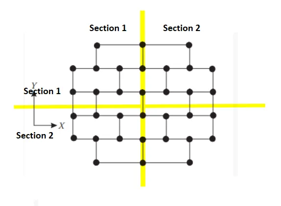
- So, if we split the above plan in either the X-direction or in the Y-direction then we can conclude that the half of its plan is the exact image of the half of its plan then it means the above given plan is symmetric in both the direction.
(b) Redundancy:
(i) Checking the redundancy in the X-direction:
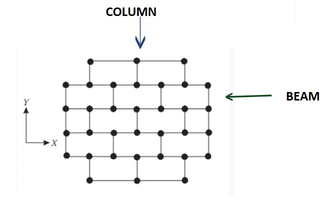
- In the above given plan, there are multiple dots and the lines.
- So, these dots represent the columns and the line represents the beams.
- So, if we observe the above given plan then we can see that the columns in the X-directions are more and evenly spread in the middle of the plan.
- So, we can say that the structure is redundant in the X-direction.
- But if we observe the above plan then we can see that the columns in the top and the bottom there are a smaller number of columns as compared to the middle portion of the plan but these columns are evenly spread so we can say the structure in the X-direction is redundant in nature.
(ii) Checking the redundancy in the Y-direction:
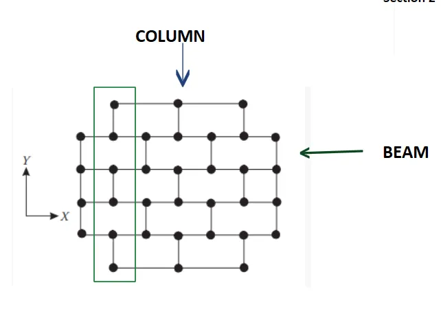
- In the above given plan, there are multiple dots and the lines.
- So, these dots represent the columns and the line represents the beams.
- So, if we observe the above given plan then we can see that the columns in the Y-directions are evenly spread but they are lesser in number if we observe the above plan in the Y-direction.
- So, we can conclude that the redundancy in the Y-direction is lesser.
Result: -
- After checking the redundancy in the X and Y direction we can conclude that the structure is more redundant in the X-direction than the Y-direction.
(c) Bi-directional Stiffness:
(i) Bi-directional stiffness along the X-direction:
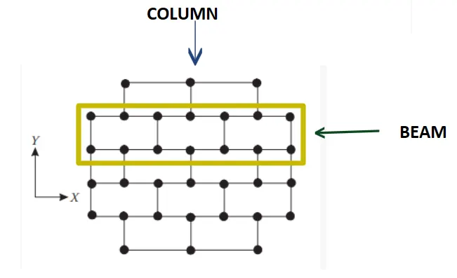
- As we can see in the above given plan, we observe that the columns in the X-directions are connected in a straight line with the beams in the continuous manner.
- That’s why we can say that the loads can be carried out and the loads can be transferred easily in the horizontal direction i.e., X-direction.
- After this study we can conclude that the frame is stronger in the bi-lateral stiffness in the X-direction.
(ii) Bi-directional stiffness along the Y-direction:
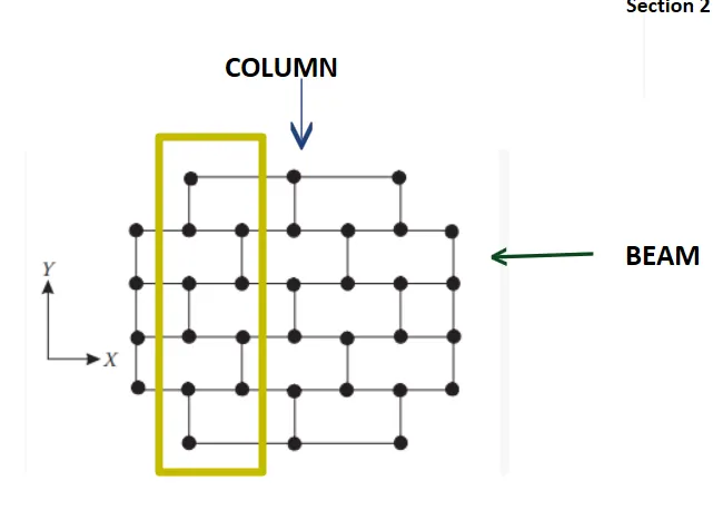
- If we see the above given plan thoroughly than we can see that the columns in the Y-direction connected in a straight line, but as we can see in the above given image that the beams are not connecting all the columns properly.
- As we can see that there is empty space after the each one beam.
- Therefore, the loads cannot be transferred easily in the Y-direction.
- Therefore, we can conclude that the above given frame is weak in the bi-lateral stiffness in the Y-direction.
Result: -
- After checking the bi-lateral stiffness in both the direction i.e., X and Y direction we can conclude that the frame is stronger in the X-direction according to the bi-lateral stiffness that the Y-direction.
(d) Ductility:
(i) Ductility along the X-direction:
- As we can see in the above given plan the beams are connecting all the columns in the X-direction and the stiffness is more in the X-direction because the number of columns is more the X-direction.
- So, we can conclude that the frame is more ductile in the X-direction.
(ii) Ductility along the Y-direction:
- As we can see in the above given plan that the beams are not connected to each and every column of this frame in the Y-direction.
- And the stiffness of this frame in the Y-direction is also less because of the lesser number of the beams in the Y-direction.
- So, we can conclude that the frame is not ductile in the Y-direction.
Result: -
- So, if we compare the ductility in both the direction i.e, X and Y direction then we can say that the frame in the X-direction is more ductile and the frame in the Y-direction is not ductile due to the lesser number of beams in the Y-direction.
Q.2: - What are the possible sources of irregularity in the building shown here? Explain how, as an engineer, each of these irregularities should be dealt with.

Answer: - The possible sources of irregularity in the building are listed and discussed below:
- Failure at the middle of the building due to the soft-storey.
- Vertical irregularity.
- Slopy base.
(i) Soft storey:
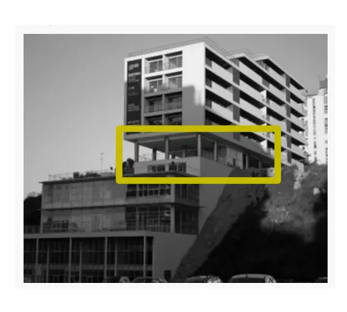
- As we can see in the above given image that this building at the 6th floor has a soft storey because it has uncovered opening.
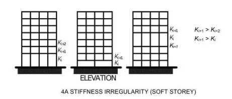
- As we can see that there is no partition wall or no occupancy or any other shear wall or any other type of support elements etc nothing is there to support the upper blocks of the building during the earthquake and this will also cause plastic hinge at the columns. According to the reference IS 1983-2016 Figure 4A, this has to be checked and we have to design the building accordingly. So that there will be no mistake in designing the building.
- Below are the images showing the stiffness irregularities (soft storey):
(ii) Vertical irregularities:
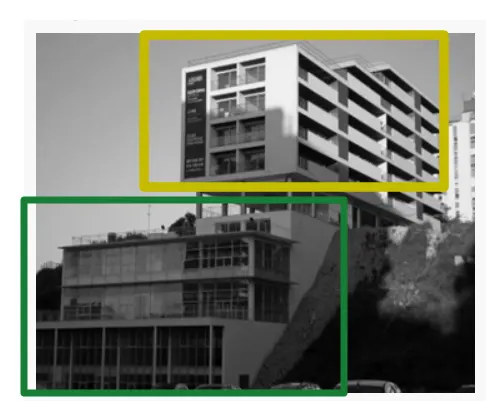
- If we observe the above given plan carefully then we will be able to see that the building plan area is bigger in the bottom section and the building plan area keeps reducing as it goes up. In short it means that the building plan area reduces with the increase in the height as we can see clearly in the above image.
- The area in the green rectangle has bigger plan area than that of the area that are in the yellow rectangle.
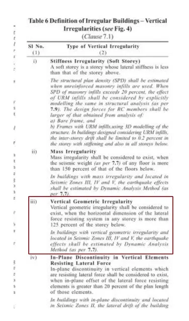
- The building offset has to be checked out with the reference of IS 1893-2016 table no.6 serial no (iii). The image regarding this reference is given below:
(iii) Slopy base:
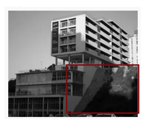
- If we observe properly then we can see that at the right-hand side of the image there is sloping ground and this building is constructed at that sloping area.
- Which means that the there are risks that this building may collapse during the earthquake.
- And this will lead to the variation in the stiffness as we can conclude properly.
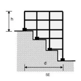
- So according to the IS 1893-2016 FIG 5E we have some standards in order to design a building in such slopy areas and if we follow these standards then there is high possibility that we can save the structure from collapse during the earthquake attack.
Q.3: - A 4-storey hotel building has an open ground floor for the restaurant. Story 2 to 4 has one row of rooms along each long side in plan, separated by a corridor. The two short sides of the perimeter are fully in-filled in all storeys, except for certain openings at the ends of the corridor at storeys 2 to 4 and along the right-hand side of the ground floor. There is a staircase near the upper left-hand corner, with straight flights between landings at floor levels and in-between floors. Cross-section dimensions are written next to the member no. in meters.
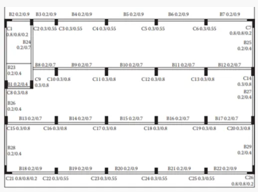
Comment on the features of the structural design and of the layout of infills which are important for earthquake resistance and seismic performance. How do they relate to the almost full collapse of this building (the extreme left-hand bay with the staircase survived, as well as one long-side façade in the rear end, and the frame along the right-hand side in plan).

Answer: -
(a) Open ground floor:

- As it is already mentioned in the question that the hotel building has an open ground floor for the restaurant, it means that the restaurant has a soft storey mechanism acting on the building that cause the damage to the building. And this is one of the reasons why this restaurant building collapse.
(b) Rooms along two bay separated by an open space:
- The bay that are filled with the rooms will have higher mass than the middle bay which is opened for the corridor.
- So this will cause mass irregularity along the height uniformity.
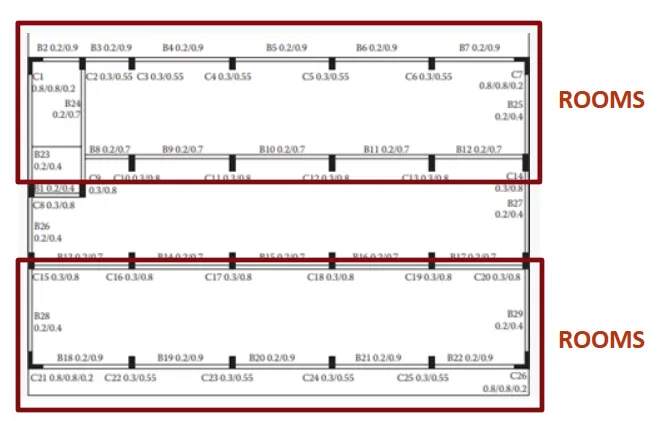
- As we can see at the above image that the upper portion and the bottom portion is for the rooms and because of that rooms these portions have higher mass because of the various furniture load,live loads etc.
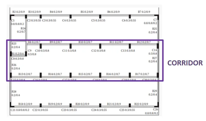
- And the middle portion they left for the corridor as we can see in the above given image.
(c) Two short sides covers with the infill walls:

- As we can see that the two shorter sides of the perimeter are not in filled in all the storeys, except for the certain openings at the ends of the corridor at the 2nd and the 4th floor and along the right-hand side of the ground floor.
- This means that the building at the left and the right of the given building is more stiffer during the earthquake.
- And they have built non-structural wall.
(d) Staircase portion at the left top corner:

- As we can see that the staircase and the lift portion of the building is not affected with the seismic force. These are the only elements that are not affected during the earthquake force.
- This is because the usually the staircase and the lift portion are stiffer than the other members of the building. Its means it does not bend easily with the external forces and that is the reason that the staircase and the lift is intact in the position with much harm.
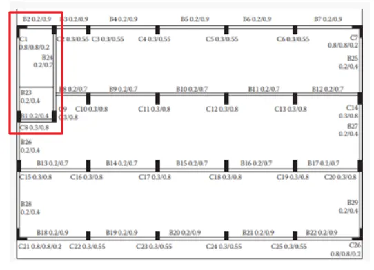
- As we can see in the image only the staircase part is intact because of the concrete elements.
- So, the staircase is the only intact portion which contains more stiffness in the given structure or hotel.
(e) No frame connection along the Y-direction:
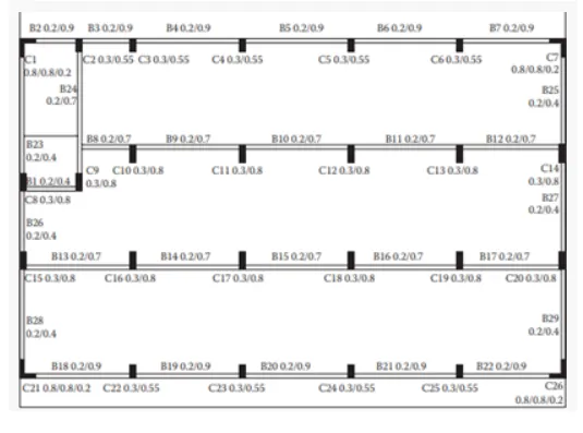
- As we can see in the above image that there are no structural beams that are provided along the Y-direction between the columns.
- This means that the building is more vulnerable during the earthquake because of the no frame connection along the Y-direction.
- That’s why we have to be more careful while designing the structures because a little mistake can lead to a very serious problem.
(f) Beams connected along column minor axis:
- As we can see in the above image that the columns have the longer direction in the Y-direction.
- But there is no direct connection or frame in the Y-direction which may connects the beam in the Y-direction.
- There are columns that are connected in the X-direction but the large side of the column is in the Y-direction which means that they are more stiffer in that direction which can attract more lesser lateral force and this is one of the reason for the collapse of this building.
(g) Variation in column sizes:
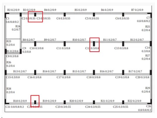
- As we can see in the above given image that the sizes of the columns are different.
- We can say that the size of the interior column is big in size and the size of the exterior column is smaller as we can see in the above image.
- And because of the difference in the size of the columns the structure collapse because it may suffer heavy out of plan shear.