Channel flow simulation using CONVERGE CFD
Abstract:
In this project a channel flow study is conducted. With different mesh sizes, the simulation is performed to observe output parameters like pressure, mass flow, velocity etc. The simulation set up is done in converge studio, run in Cygwin and post processed in paraview.
Aim:
Perform channel flow simulation at different grid sizes with converge cfd.
Objective:
1. For this challenge, we will be setting up a channel flow tutorial.
2. As you watch these videos, setup the case in CONVERGE
3. Make sure the inlet pressure and initial pressure are the same.
4. Once you have the base setup ready, run the case for three different base mesh sizes
i.e You need to run 3 simulations and compare the results between all the 3 simulations.
3 different base mesh sizes are,
- dx = 2e-4m, dy = 2e-4m, dz = 2e-4m
- dx = 1.5e-4m, dy = 1.5e-4m, dz = 1.5e-4m
- dx = 1.0e-4m, dy = 1.0e-4m, dz = 1.0e-4m
1. Velocity and pressure contours for all the 3 base mesh sizes
2. Show mesh (i.e surface with edges) for the 3 base mesh sizes
3. Plots for velocity, pressure,mass flow rate and total cell count for all 3 base mesh sizes.
4. Explain the plots and write a detailed report on your project.
Modelling approach:
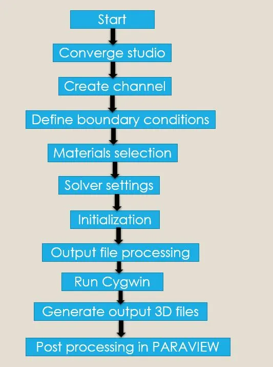
Case setup:
- Open converge studio console
- To create geometry, click on geometry icon>> select create >>select shape>> select box and give the required dimension
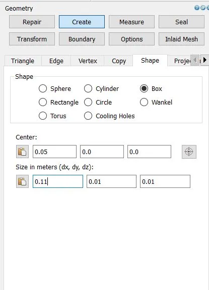
- The geometry is now created.
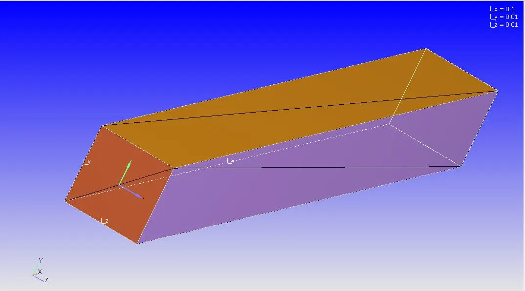
- Go to the right-hand side case set up option, there we will find many setting up option.
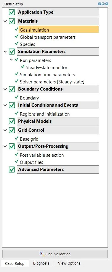
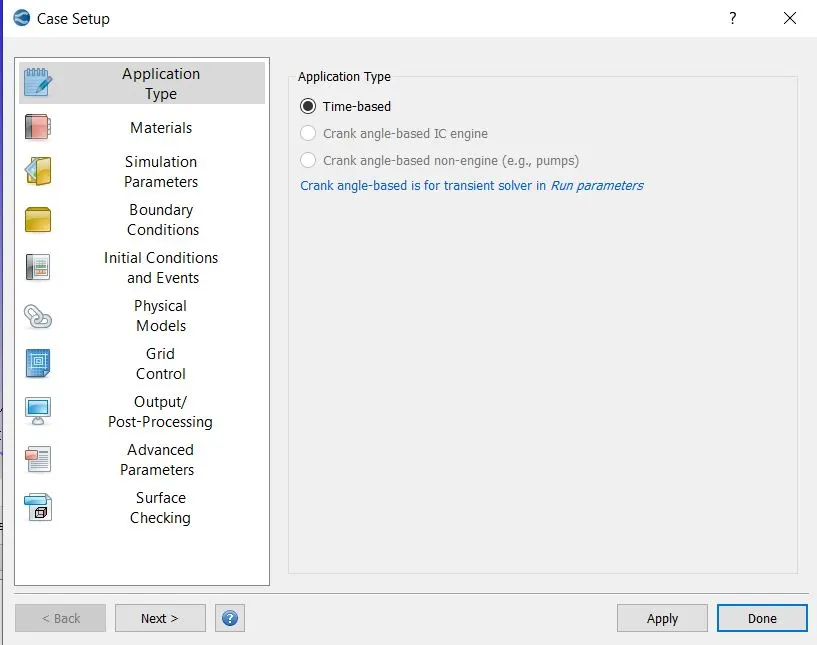
- Select application option>>select time based option.
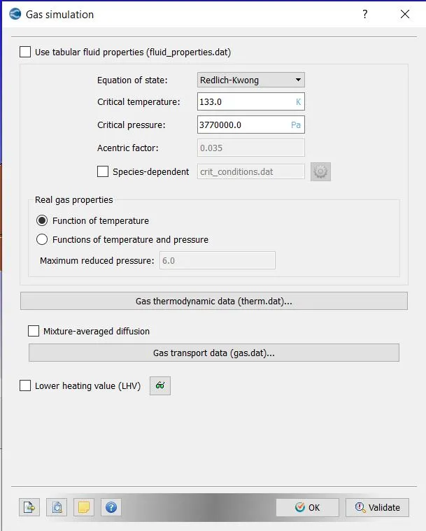
- Go to materials>> select gas simulation >> click ok
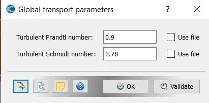
- Go to global transport parameters >> select ok.
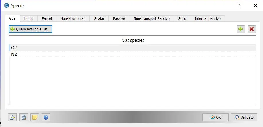
- Select species>>provide O2 andN2 as species>>select ok
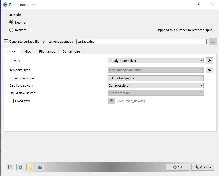
- Go to simulation parameters>> select run parameters>> choose steady state solver with full hydrodynamic case.
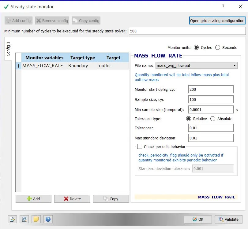
- Go to steady state monitor>> provide monitor variable as mass flow rate>> select target type boundary>> select target as outlet
- Provide the min no of cycles for steady state solver>> provide monitor delay start, sample size.
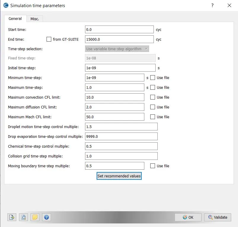
- Select simulation time parameter>>provide end time as 15000 cycles>> provide initial and min time step of 1e-9 and max time step of 1
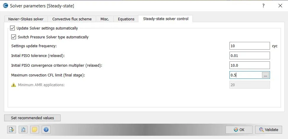
- Go to solver parameter setting>> choose density based >> go to equation >>select pressure and set precondition to none>> go to solver control and define the cfl limit to 0.5
- Go to boundary>> define all boundary region name with ID
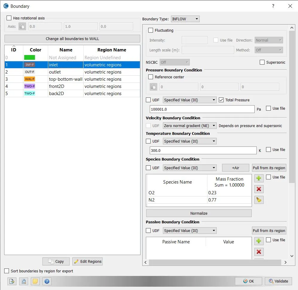
- For inlet > > choose inflow type
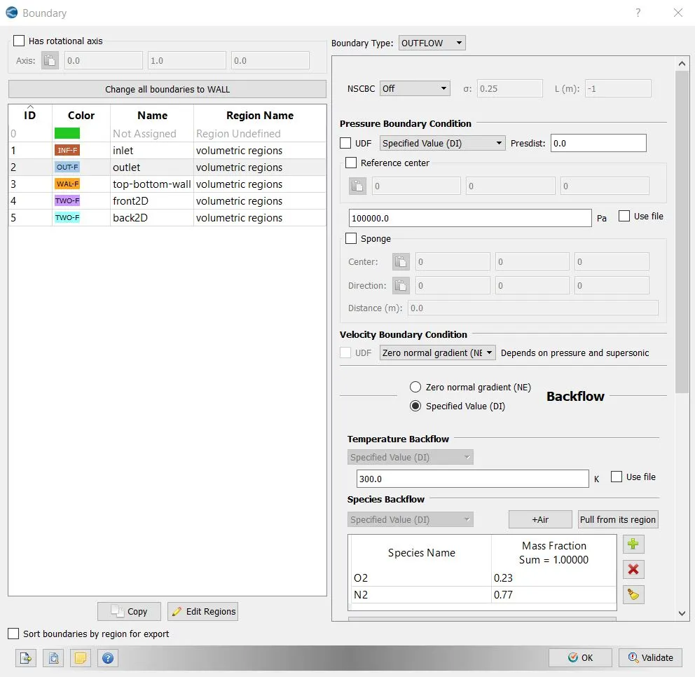
- For outlet > > choose outflow type
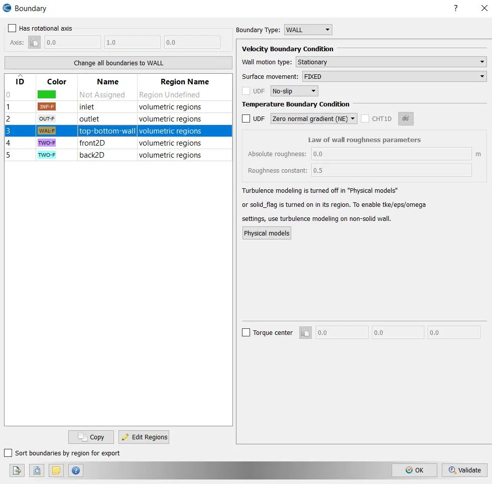
- For top and bottom > > choose wall type
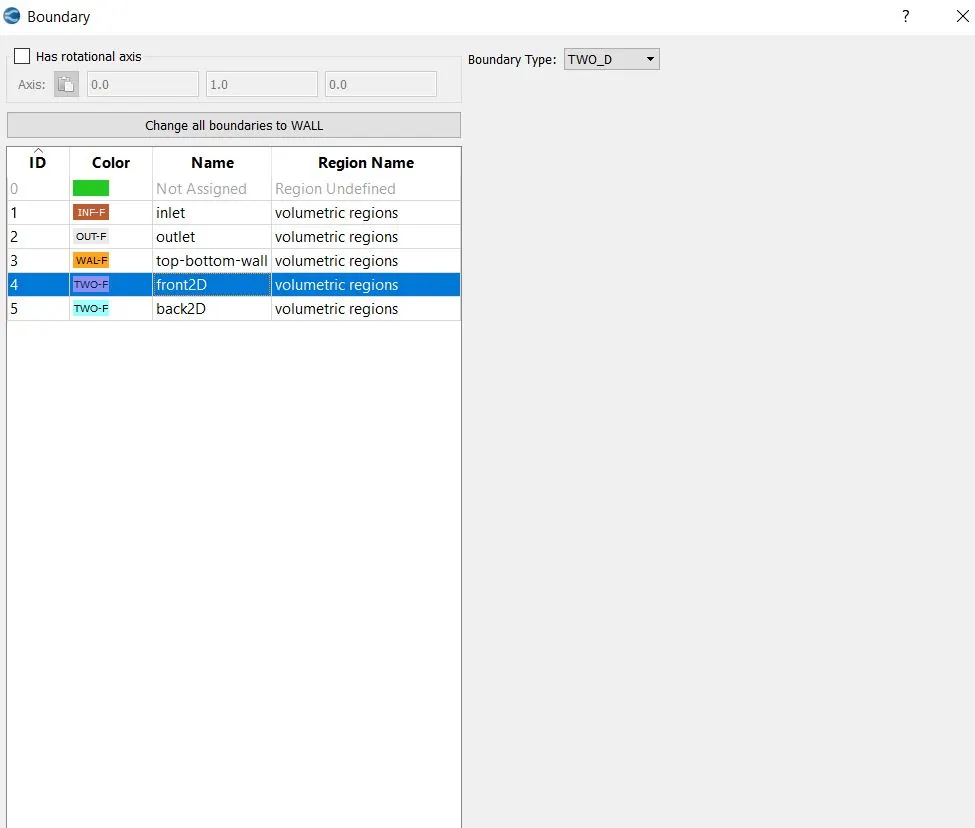
- For front and back > > choose 2D type
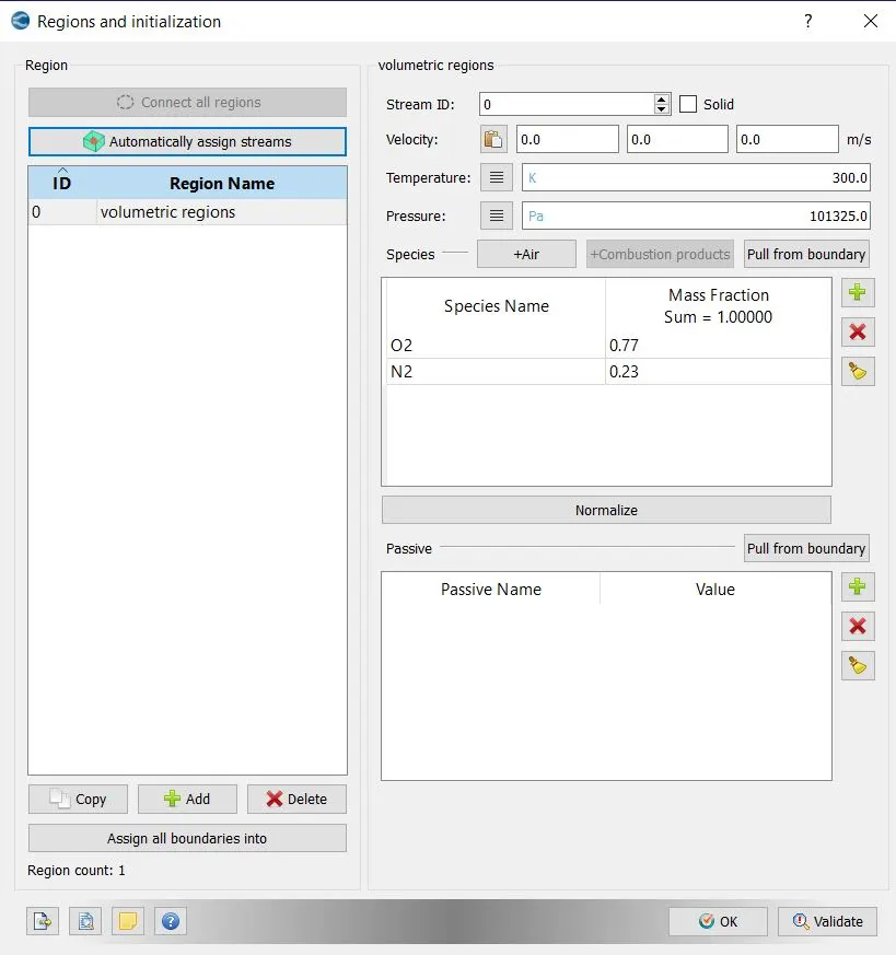
- Go to initialization>> choose region give name as volumetric region>> specify the composition of species
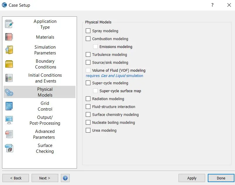
- Go to physical model>> activate it
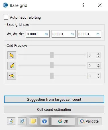
- For grid control>> provide the grid sizes in x, y, z direction
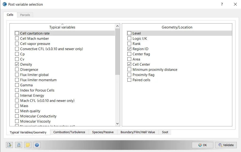
- Go to post variable selection>> select the variables for post processing
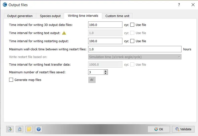
- Go to output files>> provide the time intervals of output files to be dumped.
Simulation run and post processing data:
- Export all the case set up from the converge studio
- Go to Cygwin>> go to desired path or directory
- Type the command mpiexec.exe -n 2 converge-intelmpi.exe to run the simulation.
- To post convert the output files, go to Cygwin>> type the command as ex -n 2 post_convert_msmpi_64.exe
- All the output files will be post processed in paraview atk binary format to visualize it.
Different mesh size cases:
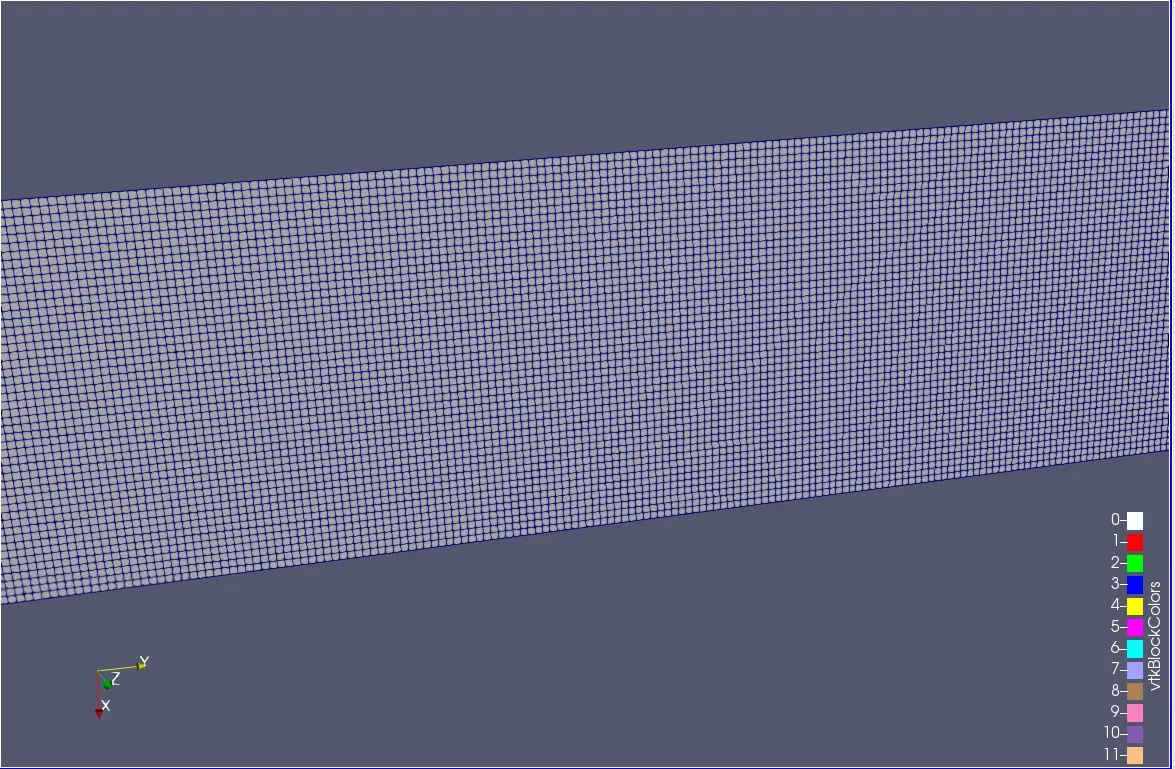
- Mesh size: 2e-4
Mesh
Inlet mass flow rate
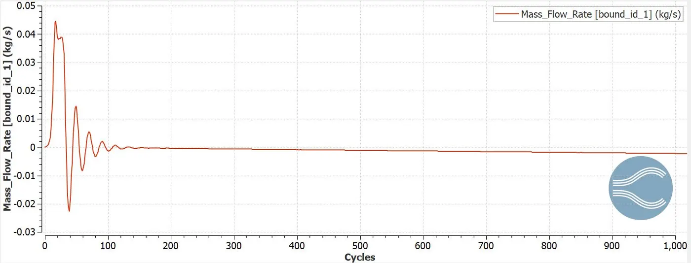
The inlet mass flow rate is maximum of 0.45kg/s at 30 cycles and reaches stability at 200 cycles.
Inlet total pressure
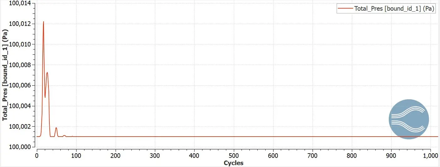
Total inlet pressure reaches maximum of 100012 pa at 30 cycles and stability at 60 cycles.
Inlet static pressure
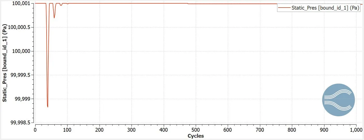
The static inlet pressure reaches maximum of 99999 pa at 50 cycles and reaches stability by 150 cycles.
Inlet velocity
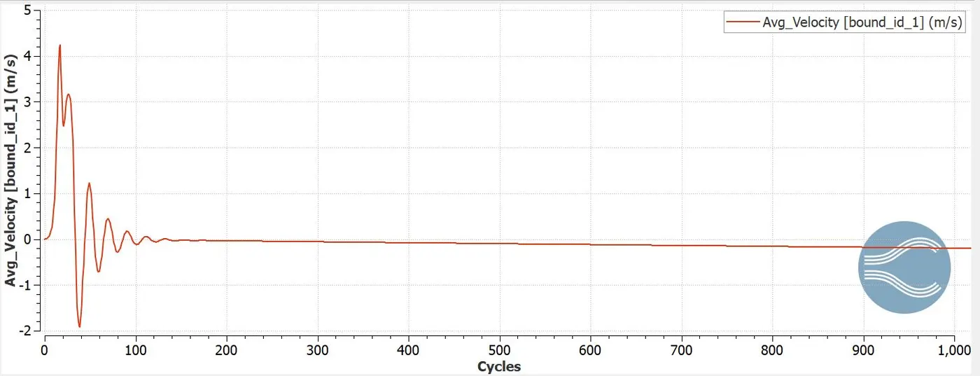
Inlet velocity reaches maximum of 4.2m/s at 30 cycles and reaches stability at 200 cycles.
Outlet mass flow rate
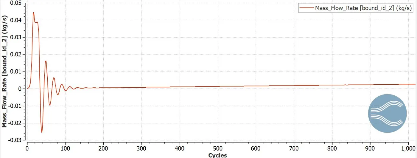
The outlet mass flow rate is maximum of 0.45kg/s at 30 cycles and reaches stability at 200 cycles.
Outlet total pressure
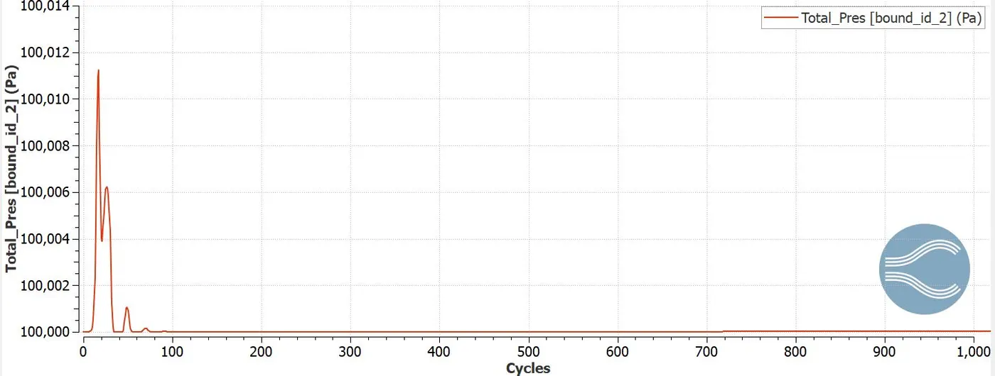
Total outlet pressure reaches maximum of 100012 pa at 30 cycles and stability at 60 cycles.
Outlet static pressure
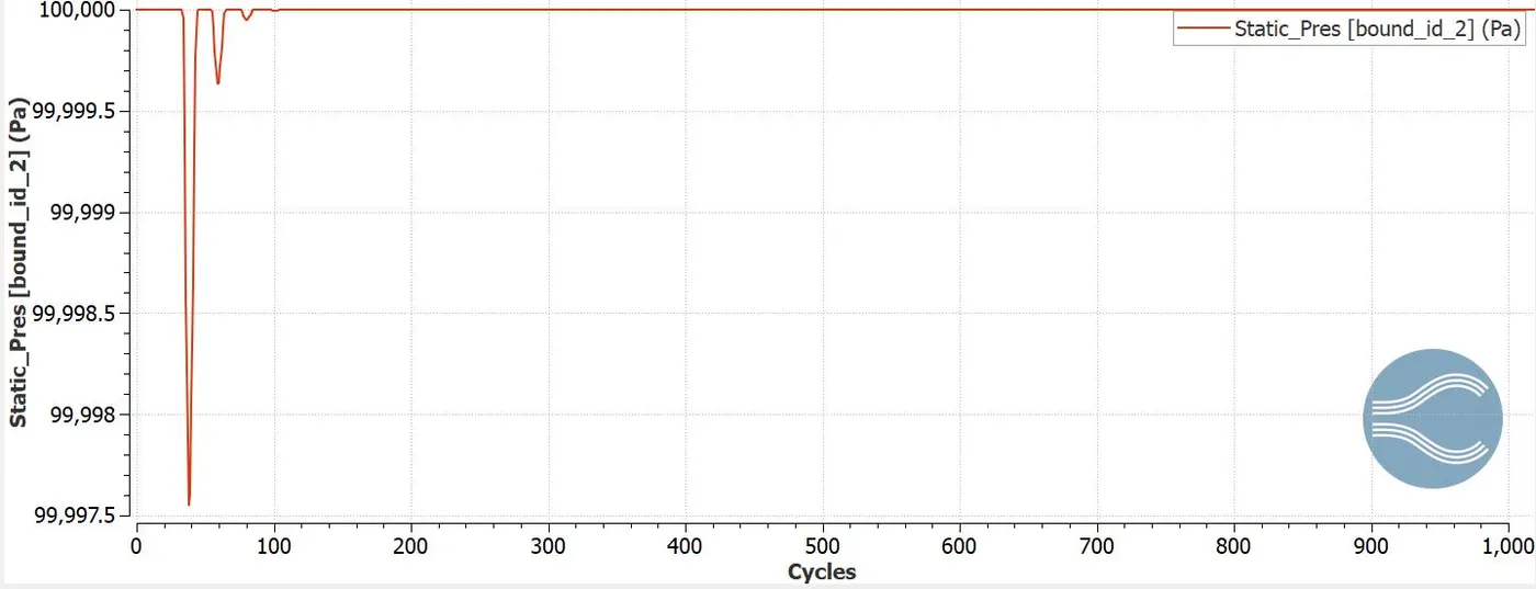
The static outlet pressure reaches maximum of 99997 pa at 50 cycles and reaches stability by 150 cycles.
Outlet velocity
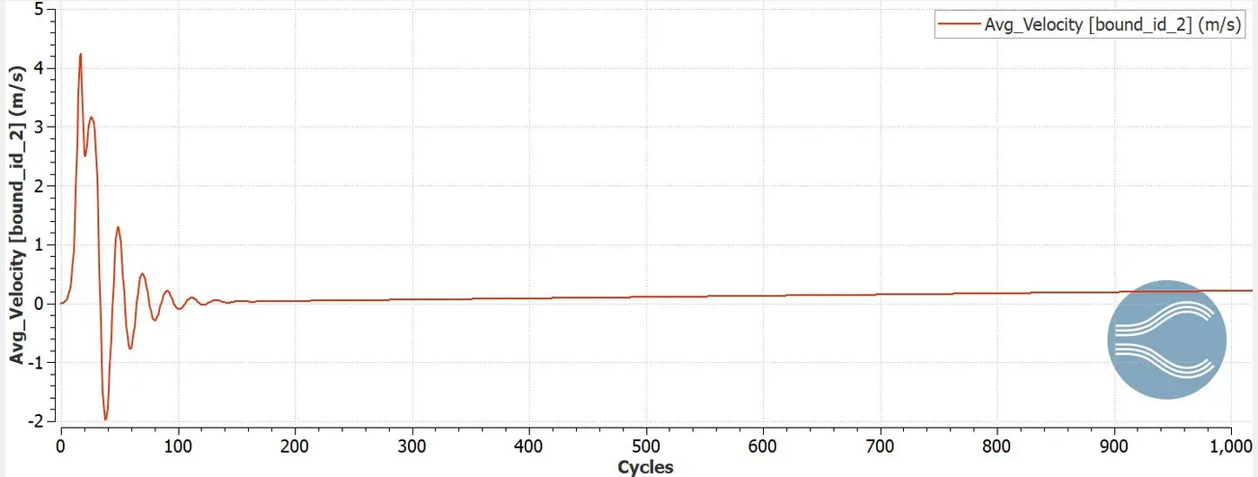
Outlet velocity reaches maximum of 4.2m/s at 30 cycles and reaches stability at 200 cycles.
Mean mass flow rate
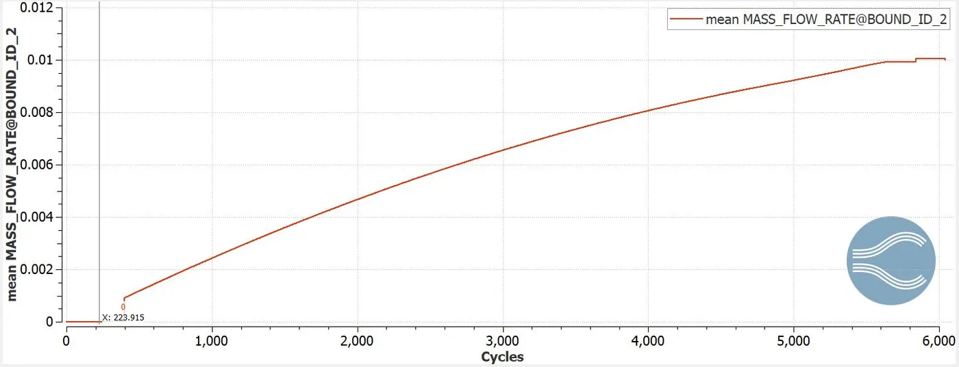
The mean mass flow rate increases from 1000 to 6000 cycles ranging from 0.002 to 0.01kg/s.
Total cell count
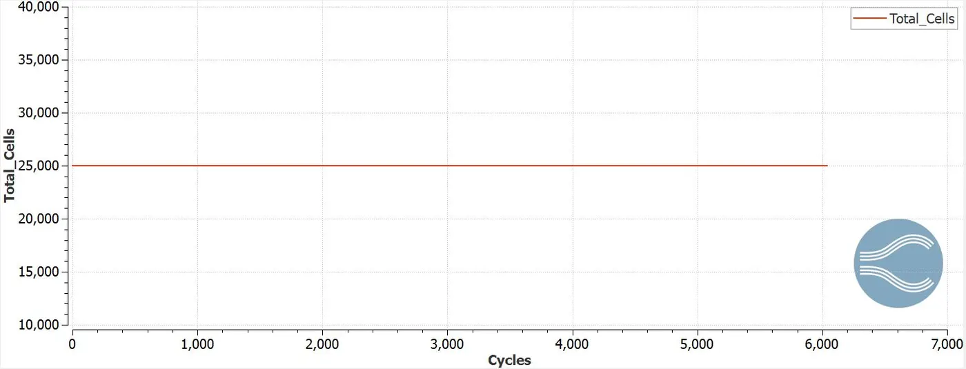
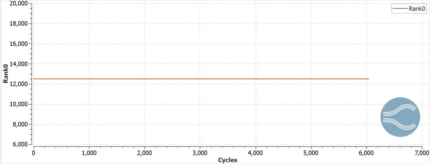
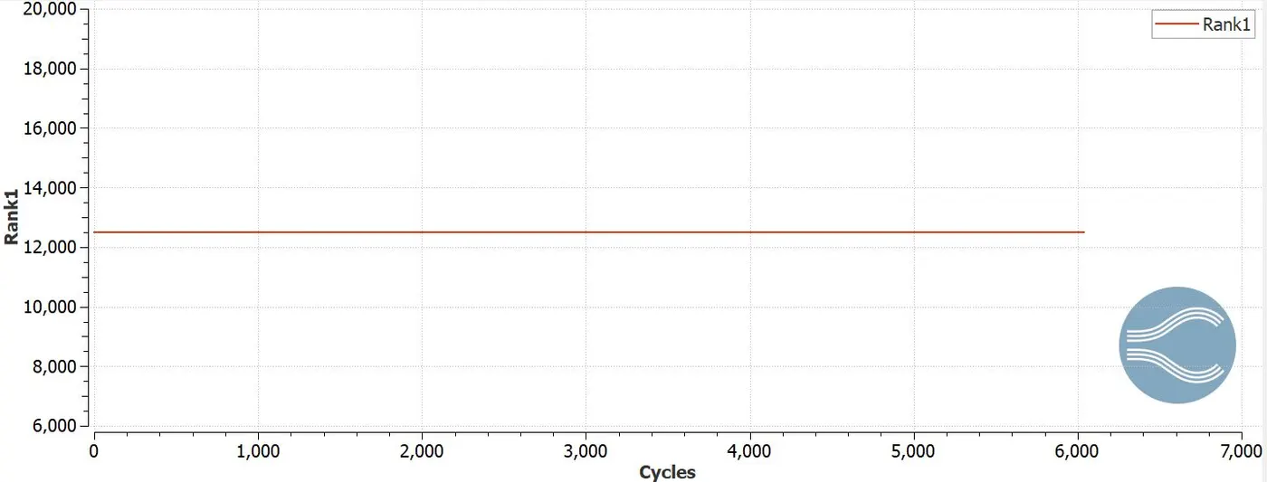
The total no of cell count is 25000 and holds 12500 cells in rank 0 and rank 1 respectively.
Post processing
Velocity contour
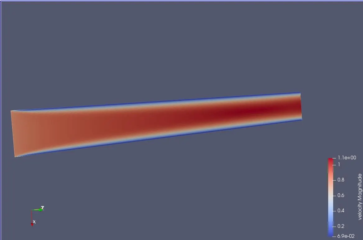
Animation
Pressure contour
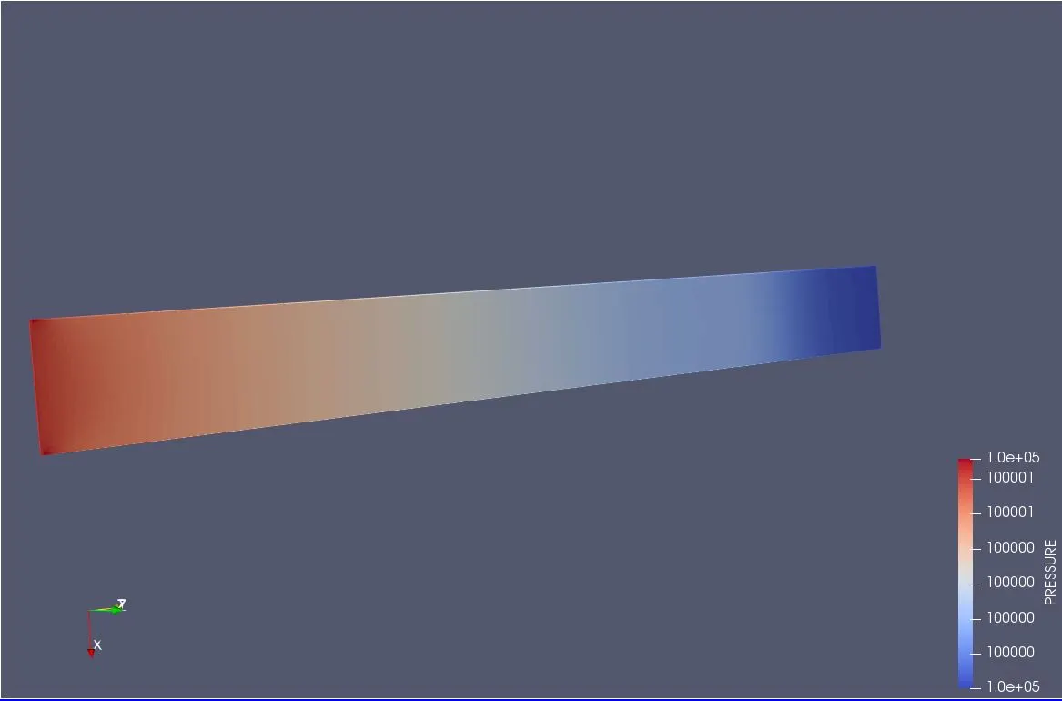
Animation
- Mesh size: 1.5e-4
Mesh
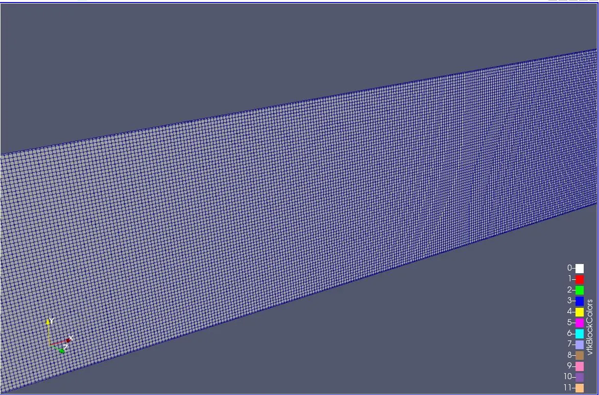
Inlet mass flow rate
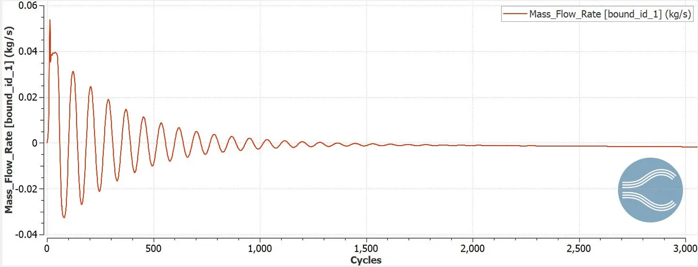
The inlet mass flow rate is maximum of 0.59kg/s at 30 cycles and reaches stability at 2000 cycles.
Inlet total pressure
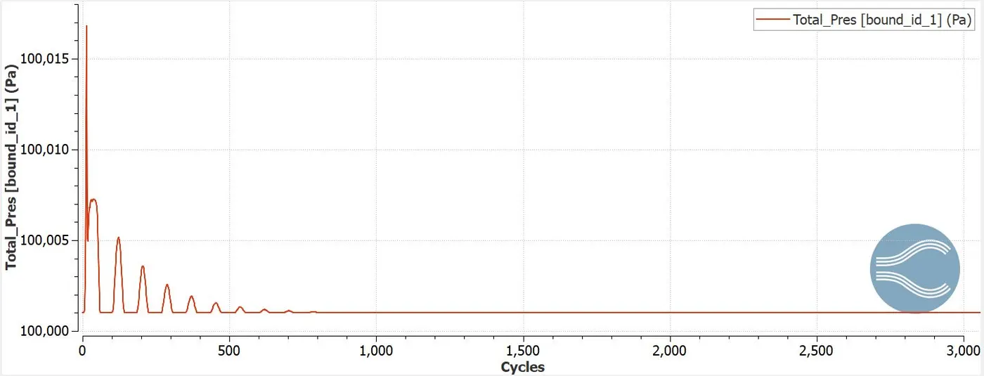
Total inlet pressure reaches maximum of 100020pa at 30 cycles and stability at 1000 cycles.
Inlet static pressure
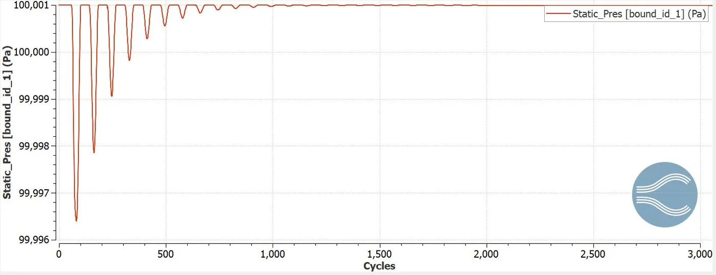
The static inlet pressure reaches maximum of 99977 pa at 50 cycles and reaches stability by 2000 cycles.
Inlet velocity
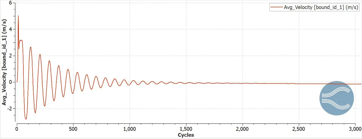
Inlet velocity reaches maximum of 5m/s at 30 cycles and reaches stability at 2000 cycles.
Outlet mass flow rate
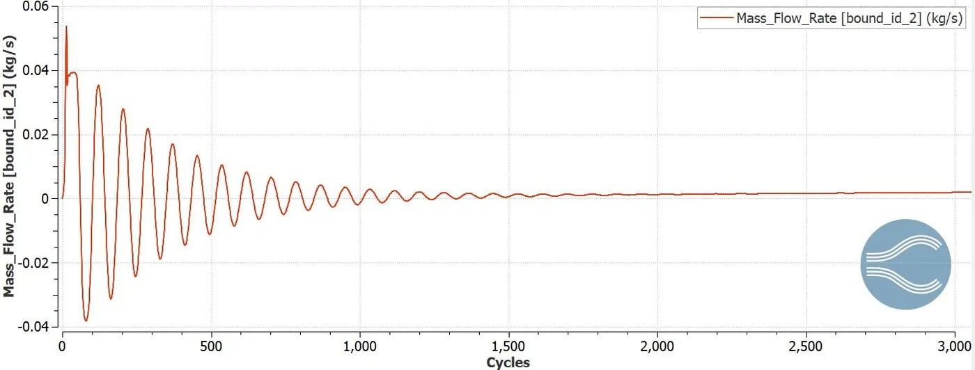
The outlet mass flow rate is maximum of 0.55kg/s at 30 cycles and reaches stability at 2000 cycles.
Outlet total pressure
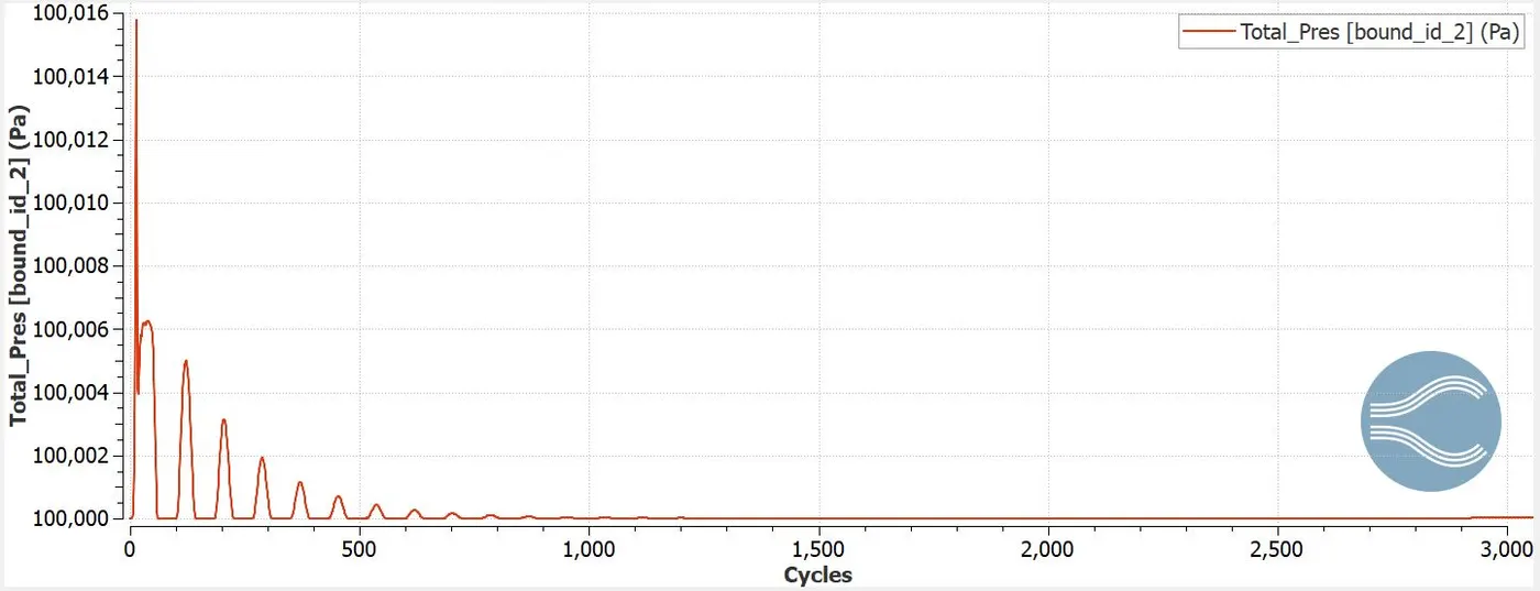
Total outlet pressure reaches maximum of 100020 pa at 30 cycles and stability at 1000cycles.
Outlet static pressure
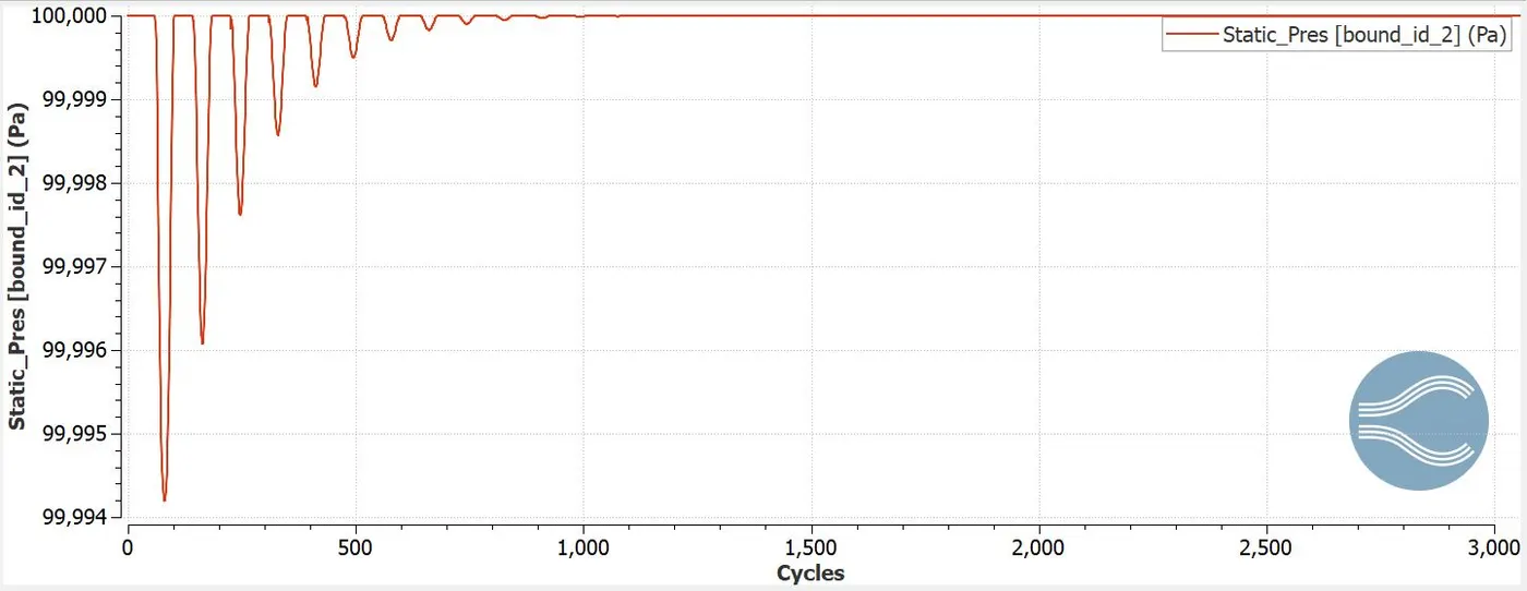
The static outlet pressure reaches maximum of 99977 pa at 50 cycles and reaches stability by 2000 cycles.
Outlet velocity
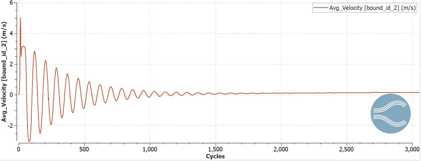
Outlet velocity reaches maximum of 4.5m/s at 30 cycles and reaches stability at 2000 cycles.
Mean mass flow rate
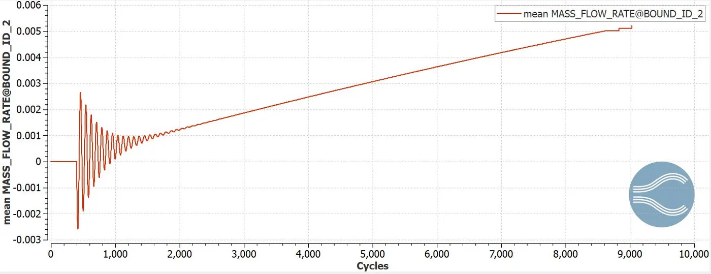
The mean mass flow rate increases from 2000 to 9000 cycles from 0 to 0.006kg/s
Total cell count
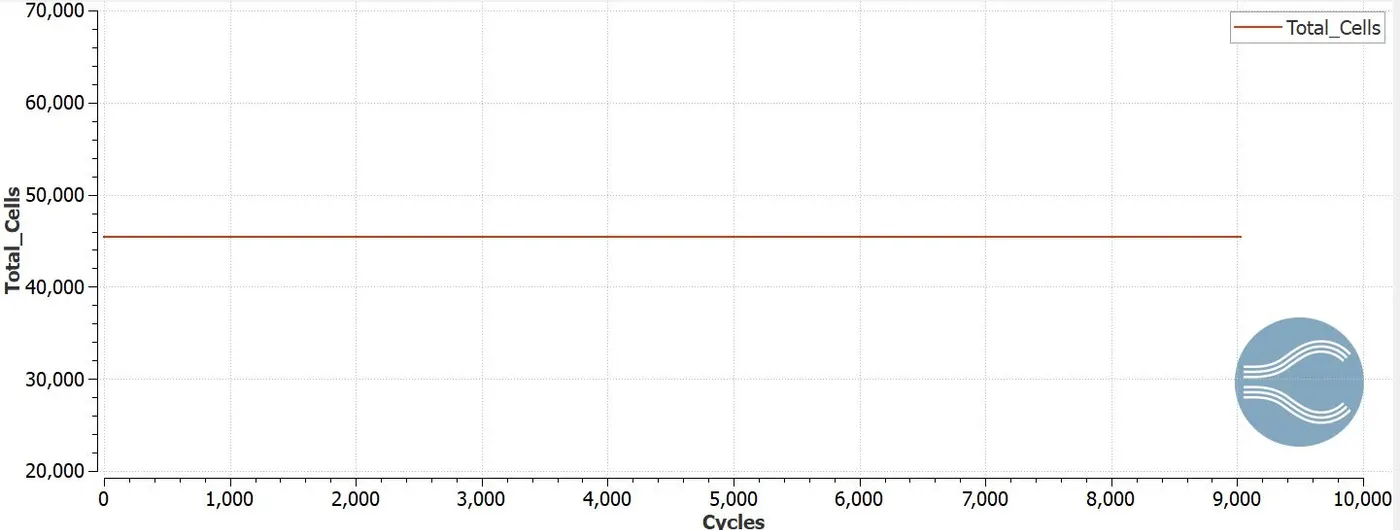
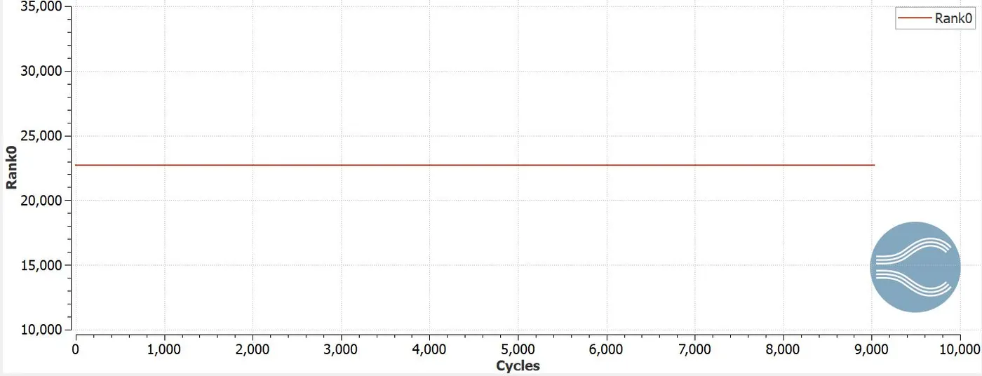
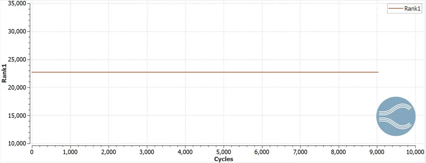
The total no of cell count is 46000 and holds 23000 cells in rank 0 and rank 1 respectively.
Post processing
Velocity contour
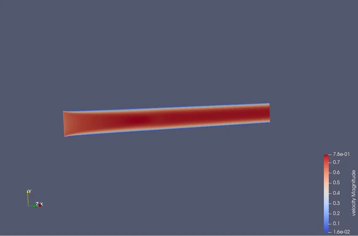
Animation
Pressure contour
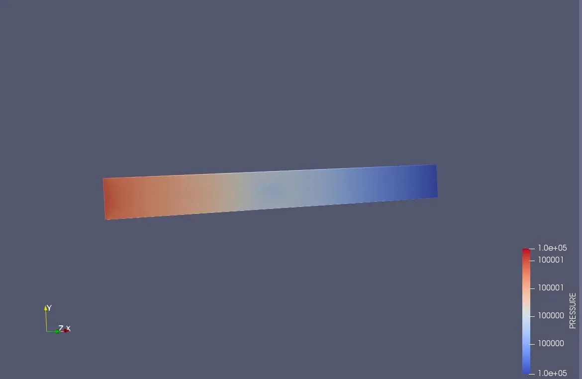
Animation
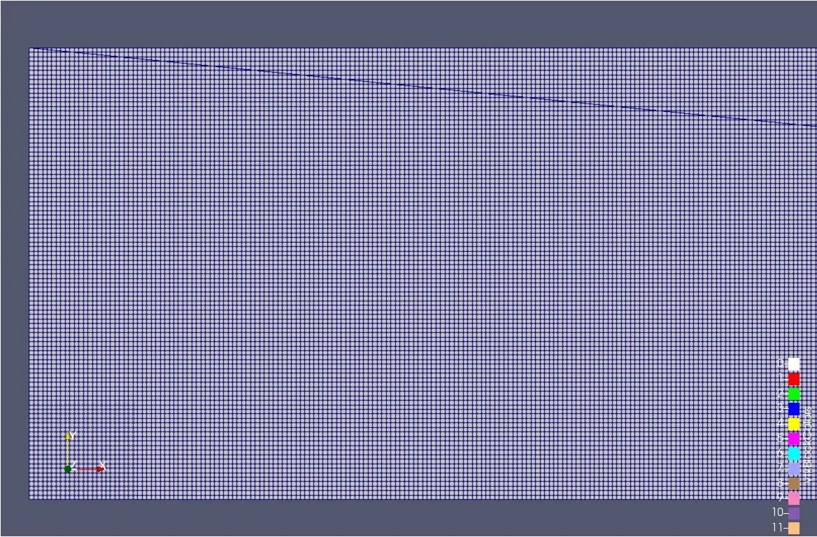
- Mesh size: 1e-4
Mesh
Inlet mass flow rate
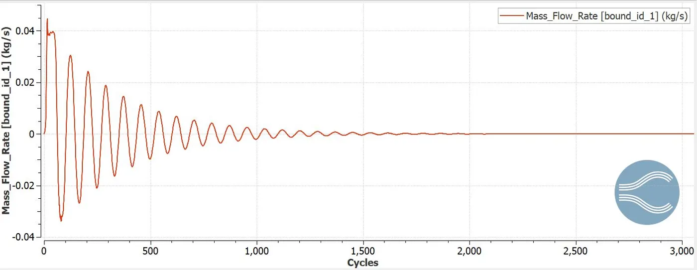
The inlet mass flow rate is maximum of 0.045kg/s at 30 cycles and reaches stability at 2000 cycles.
Inlet total pressure
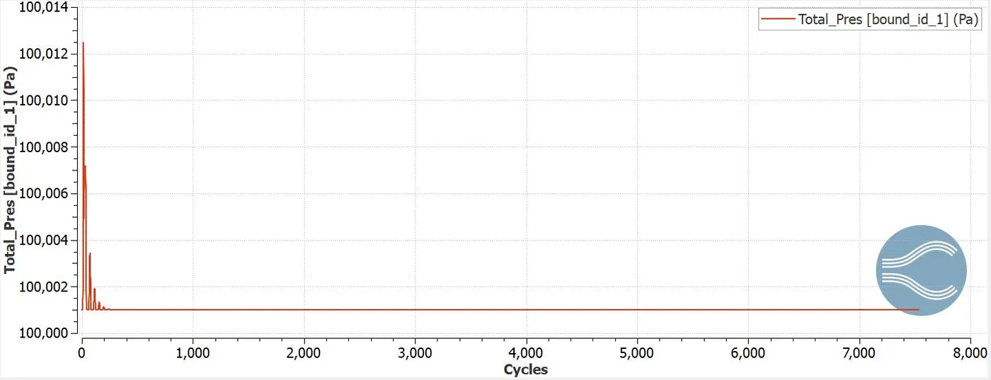
Total inlet pressure reaches maximum of 100012 pa at 30 cycles and stability at 60 cycles.
Inlet static pressure
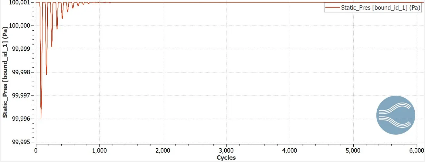
The static inlet pressure reaches maximum of 94996 pa at 50 cycles and reaches stability by 1500 cycles.
Inlet velocity
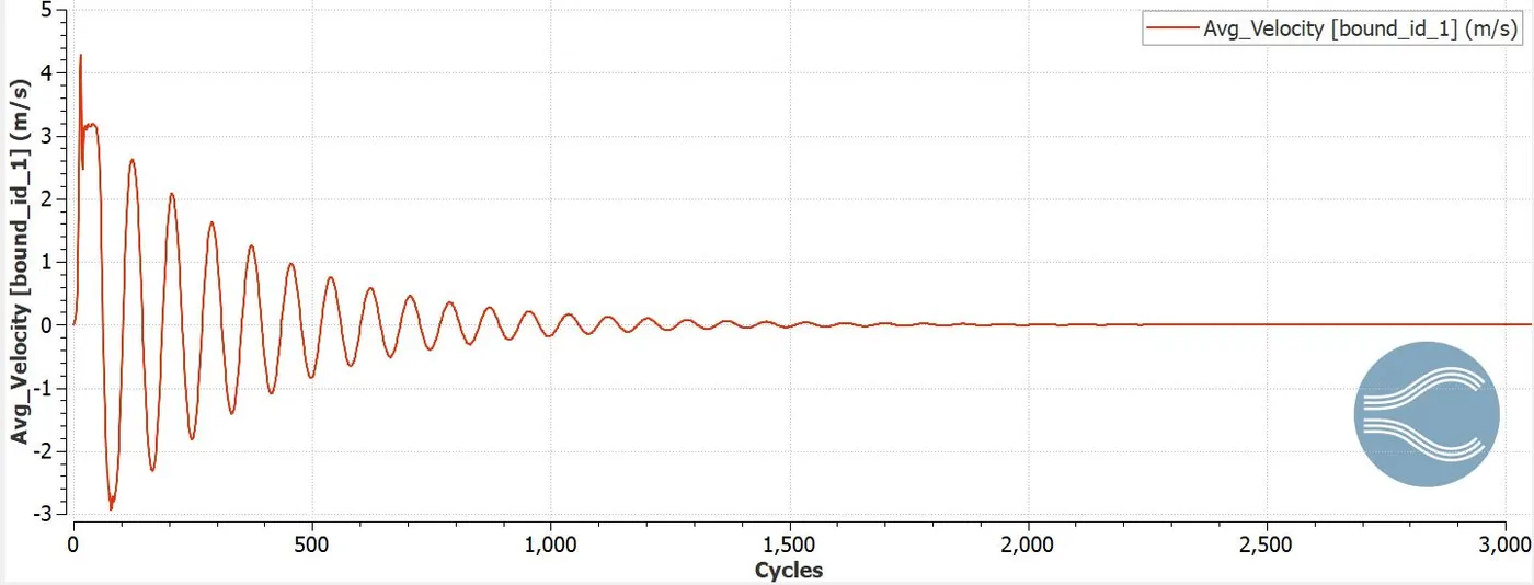
Inlet velocity reaches maximum of 4.2m/s at 30 cycles and reaches stability at 2000 cycles.
Outlet mass flow rate
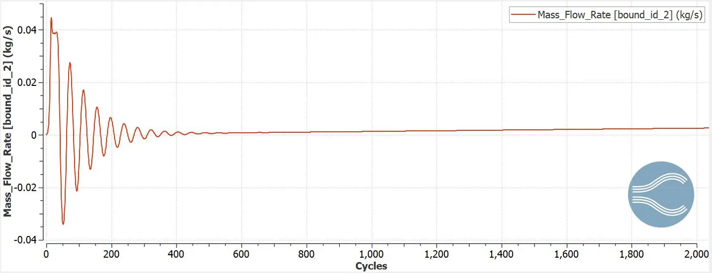
The outlet mass flow rate is maximum of 0.045kg/s at 30 cycles and reaches stability at 600 cycles.
Outlet total pressure
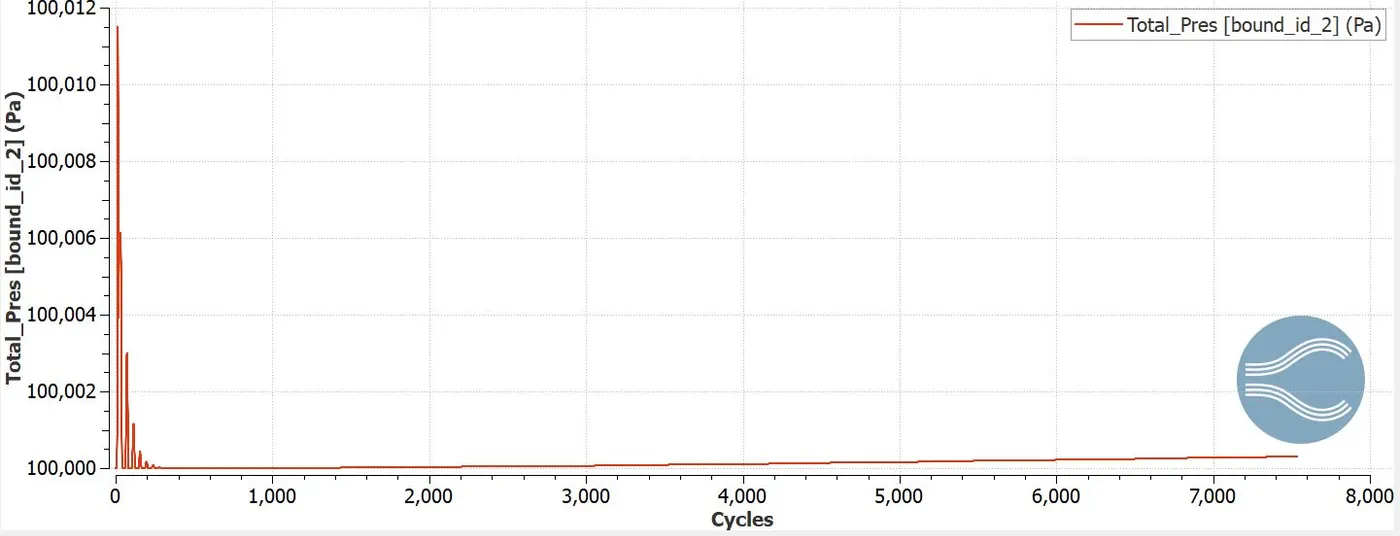
Total outlet pressure reaches maximum of 100012 pa at 30 cycles and stability at 60 cycles.
Outlet static pressure
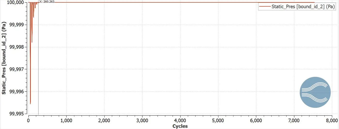
The static outlet pressure reaches maximum of 99966 pa at 50 cycles and reaches stability by 1500 cycles.
Outlet velocity
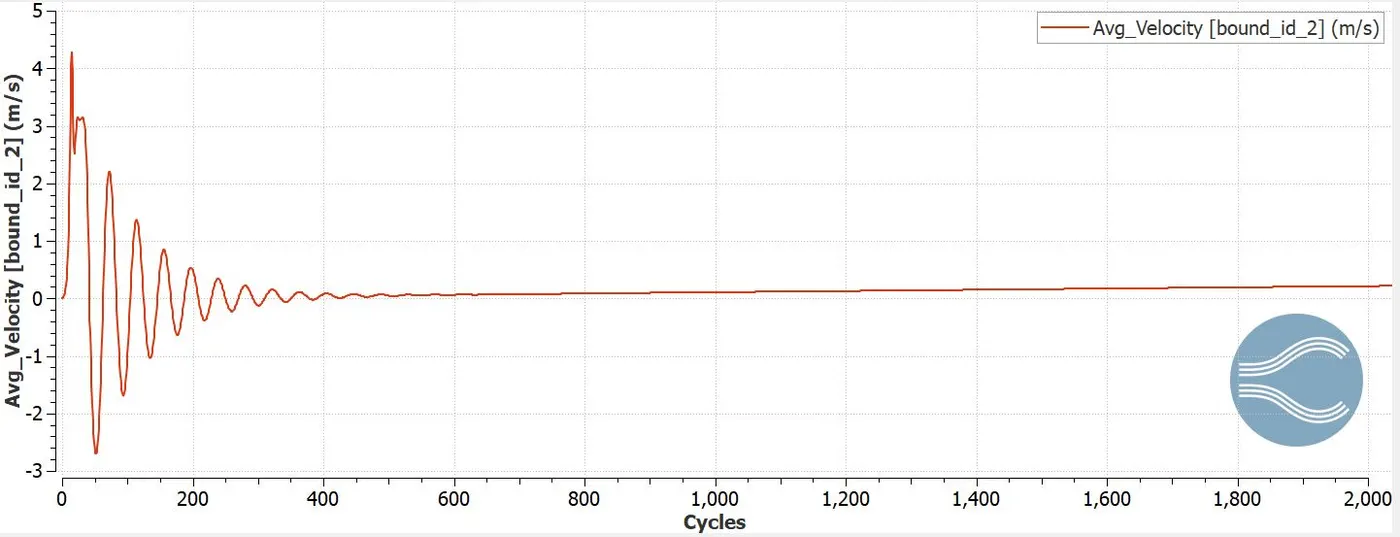
Outlet velocity reaches maximum of 4.5m/s at 30 cycles and reaches stability at 800 cycles.
Mean mass flow rate
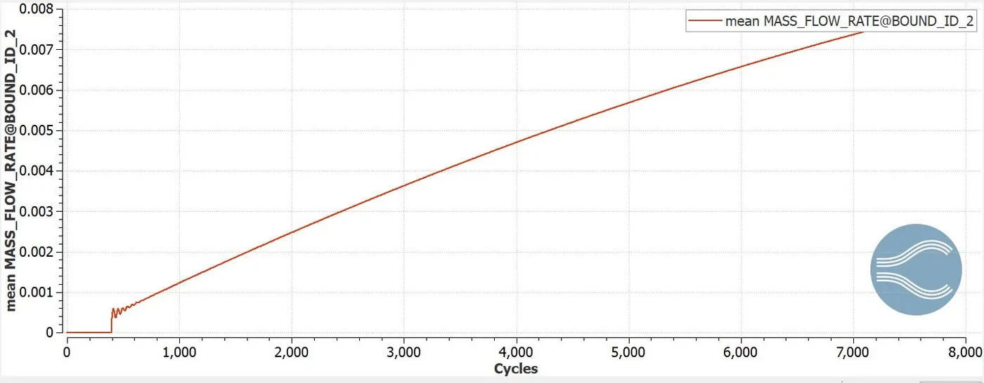
The mean mass flow rate increases from 1000 to 8000 cycles from 0.001 to 0.008kg/s
Total cell count
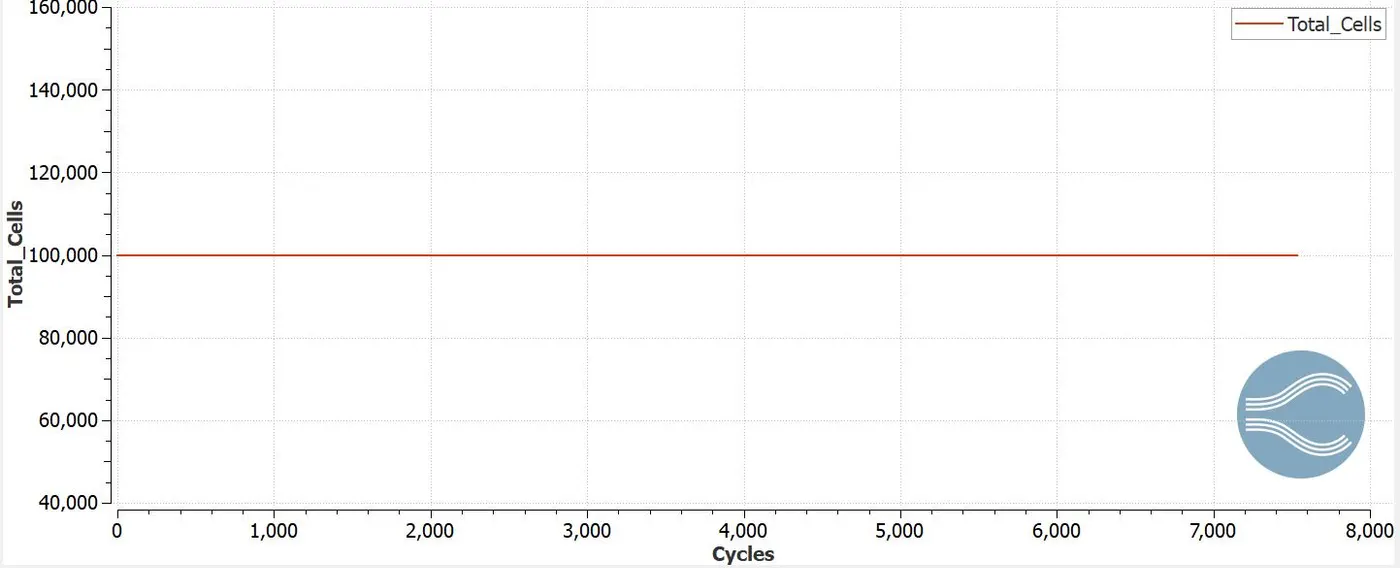
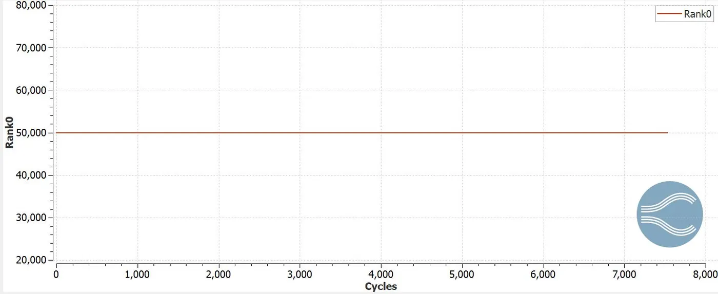
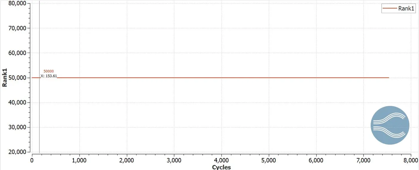
The total no of cell count is 100000 and holds 50000 cells in rank 0 and rank 1 respectively.
Post processing
Velocity contour
Animation
Pressure contour
Animation
Conclusions
- With decrease in mesh size, the computational time required to solve the boundary condition also increases.
- With decrease in mesh size, the solution converges at a bit more larger time.
- The decrease in mesh size, the no of cells allocated at the CPU becomes more and increase the time computing capability.