Gearbox Sloshing effect using Ansys Fluent
Abstract:
Gear sloshing is a major industrial problem for properly lubricating the entire gear box system, for smooth operation and power transmission. In this case, a proper lubrication of gear system is performed by multiphase simulation approach using volume of fluid method. Also, in this project, a user defined function (udf) is defined as an input parameter for the no of rotation of the gear teeth and also dynamic mesh is included. Different lubricants have been tested at different immersion level to perform satisfactorily the sloshing effect by performing a transient simulation.
Problem statement:
Part 1:
- 20% Immersion, Fluid - Engine oil.
- 30% Immersion, Fluid- Engine oil.
- 20% Immersion,Fluid-n-heptane (c7h16).
- 30% Immersion,Fluid-n-heptane (c7h16).
Part 2:
- What is Dynamic meshing? Give some other examples where dynamic meshing can be used.
- What is the fluid Sloshing effect? Discuss whether the sloshing effect is good or bad? Explain.
- What is the use of UDF?
- Discuss the common errors that occurred in the simulation. A] 'Dynamic mesh failed' error. B] 'Negative cell volume detected' error.
Objective:
To perform four simulation corresponding to gearbox simulation with two different lubricant and compare the results.
Introduction:
Fluid sloshing:
In fluid dynamic slosh refers to the movement of liquid inside another object. During the sloshing effect the fluid must have a free space to interact. This type of analysis requires CFD approach to solve the fluid-structure interaction problem. Practically fluid sloshing can cause disastrous effect in ships, aircrafts and trucks. Liquid sloshing inside a truck can cause directional instability. High hydrodynamic forces can cause breakage of stability limit. To prevent this anti-sloshing baffles are used to limit the adverse effect of sloshing.
Dynamic meshing:
Dynamic mesh refers to the situation in which the computational grid changes dynamically with CFD run. This opens up new possibility to simulate flows where the geometry changes with time. For eg flow around a falling object, combustion inside IC engines, flow around gas turbine blades.
Some of the features which ansys fluent allows for doing dynamic meshing are
- Smoothing
- Layering
- Remeshing
In smoothing the, the nodes move according to boundary motion and the element stretch out like springs to keep the nodes joined.
In layering the mesh moves layer by layer. In remeshing, the mesh is refined locally in regions that do not satisfy user specified limit on sizes and skewness. The remeshing limits require minimum and maximum element size and its skewness imit.
Advantages of dynamic mesh:
- Move boundaries of a cell zone relative to the other boundaries of zone and adjust the mesh accordingly.
- The boundaries can move rigidly with respect to each other ie linear or rotational.
- Mesh zones move adjacent to one another to link across one or more non conformal regions.
Disadvantages:
- Dynamic mesh works best for triangular shaped mesh only.
- The cell quality deteriorates if the cell boundary displacement becomes too large than local cell thickness.
- Convergence problem takes place if negative cell volume is detected.
User defined function:
User defined function or UDF is a function or basically a C program which is dynamically loaded with ansys fluent to enhance its standard features. For eg udf can be used to define specific boundary condition, material conditions and source terms in the flow regimes.
Some of the features of udf are as follows:
- Must be defined using DEFINE macros supplied by fluent database.
- The file name is defined by the name udf.h file type
- Are executed as interpreter or compiled function.
- Can be linked to Ansys fluent using gui interface.
Application of UDF:
- Customize boundary conditions
- Define material properties
- Enhance some existing ansys fluent models like discrete phase models, multi phase simulation, ordinate radiation models.
The UDF is defined for the gear motion. The first function is declared for the left gear and the second for the right gear having a function name as Define CG motion. The function takes input as time, velocity and motion of gears. Both the gears rotate with an angular velocity of 200rad/sec.
#include "udf.h"

DEFINE_CG_MOTION(right_motion, dt, vel, omega, time, dtime)
{
	vel[0] = 0.0;
	vel[1] = 0.0;
	vel[2] = 0.0;

	omega[0] = 0.0;
	omega[1] = 0.0;
	omega[2] = 2.0e2; /* [rad/s]*/
}
DEFINE_CG_MOTION(left_motion, dt, vel, omega, time, dtime)
{
	vel[0] = 0.0;
	vel[1] = 0.0;
	vel[2] = 0.0;

	omega[0] = 0.0;
	omega[1] = 0.0;
	omega[2] = -2.0e2; /* [rad/s]*/
}
Modelling aproach
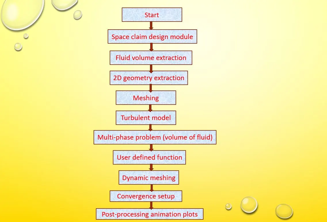
Geometry creation:
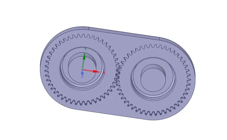
The geometry of gear box is created in solidworks along with the assembled parts as shown below:
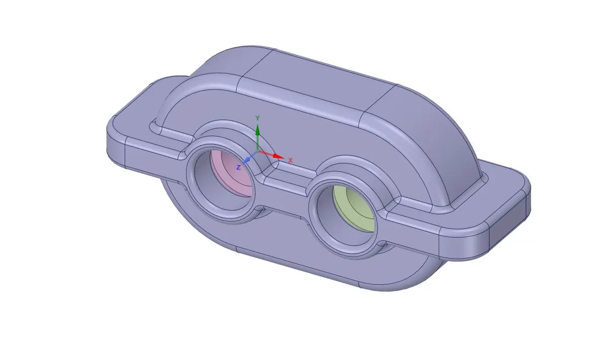
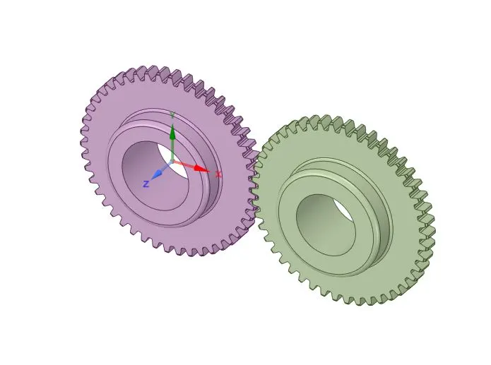
- First import the geometry in step file format to the space claim design module.
- Extract the fluid region by selecting the volume extraction mode from the prepare section.
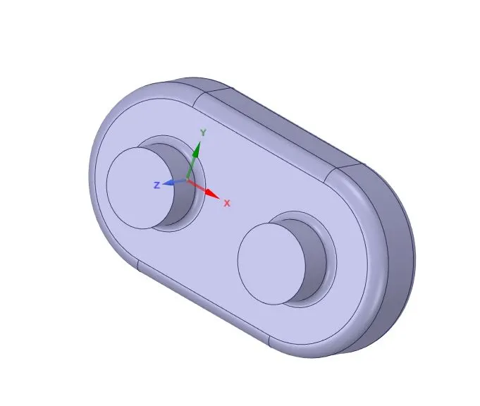
- Now suppress the outer solid geometry and hide it to view only the fluid volumetric part.
- Now we will use the split body command to split the geometry in halves.
- First select plane>> select the origin of the plane.
- Go to split body command>> select the geometry>> select the cut plane>> select the section to get removed.
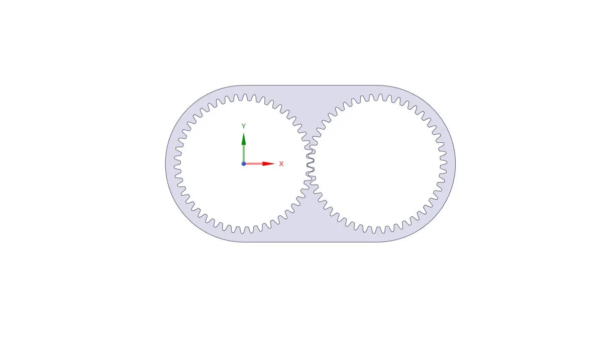
- Now ctrl+C to copy the cut section of the geometry>> open new design console>> press ctrl+v to paste the selected section in xy plane.
- The 2D geometrical section is successfully imported from the fluid volume region.
Meshing:
- Open the mesh console
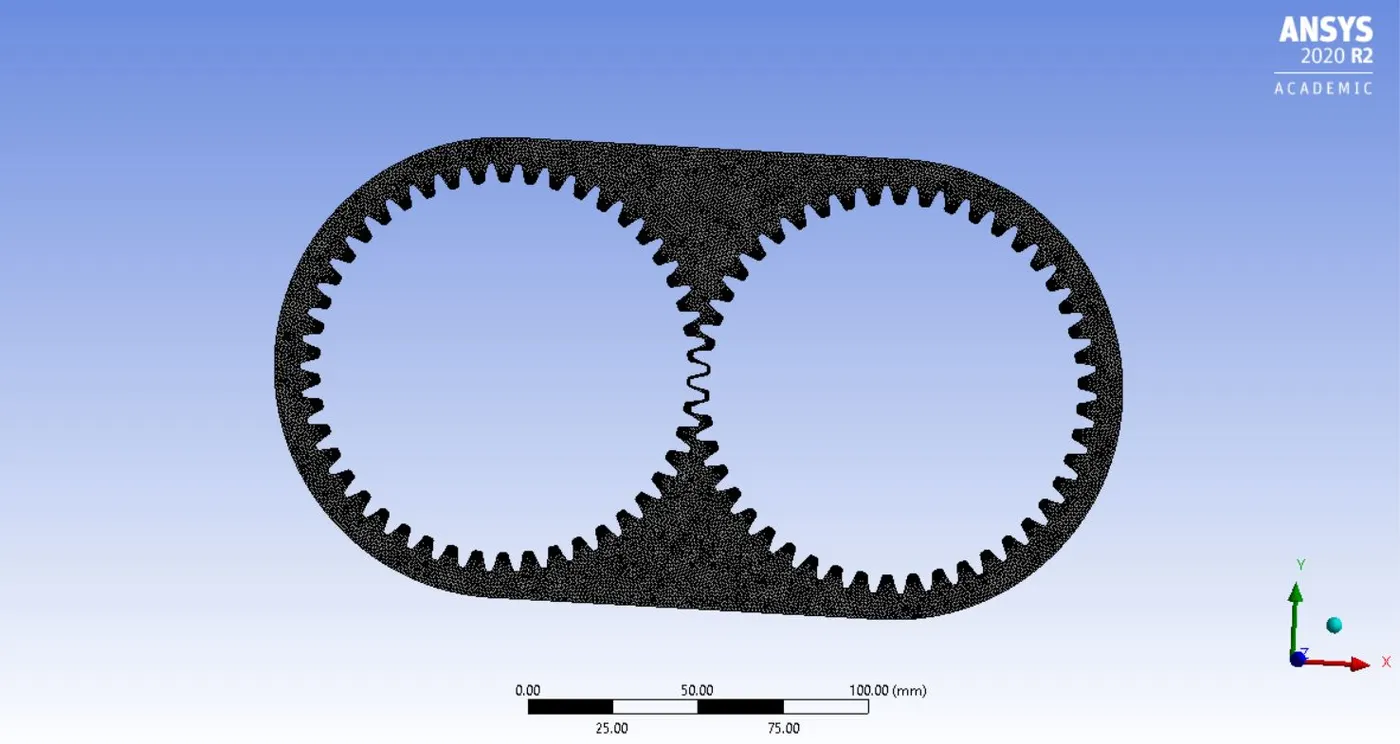
- Go to mesh option>> generate mesh. A baseline mesh will be created.
- Select sizing, give a proper mesh size of 1mm>> generate mesh, a finer mesh will be generated.
- Now we will give name selection to the gears>> select the edge option.
- Click on one edge of the gear>> press ctrl and keep on selecting rest of the edges along the entire boundary. A total of 276 edges will be selected.
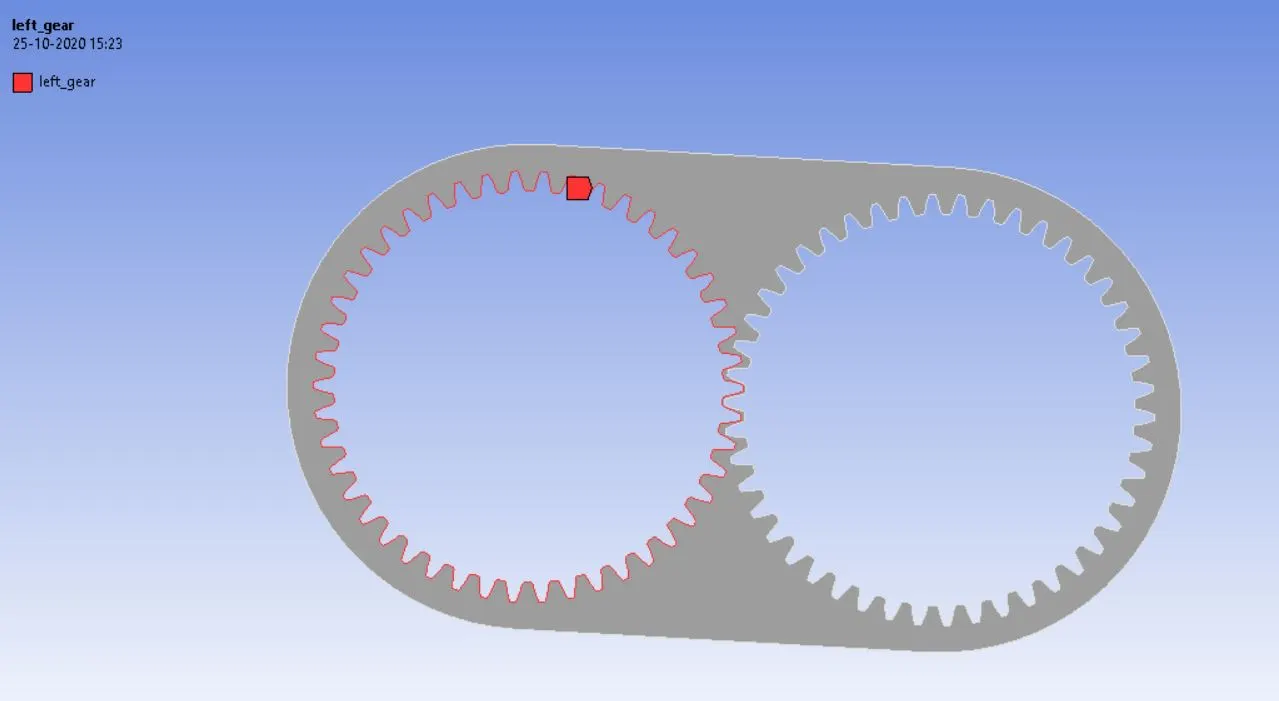
- Perform the similar trend for the other gear also, name them as left gear and right gear respectively.
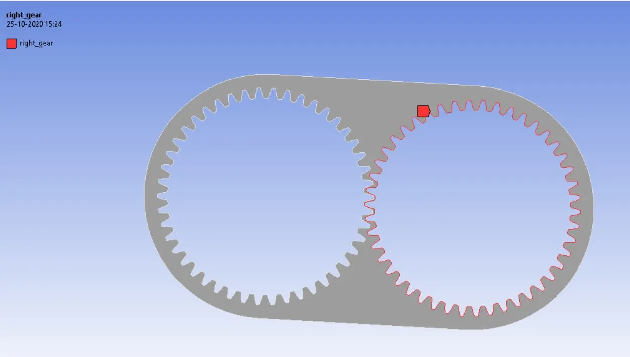
- Perform the mesh skewness and mesh quality check.
Pre-processing physics set up:
Before starting with this step, let us first find out how much fluid level is required for 20% immersion of fluid. The height of the geometry is 135mm and its 20% corresponds to 27mm. now we create a rectangle to take note of the diagonal point (xmax, ymax) and (xmin, ymin).
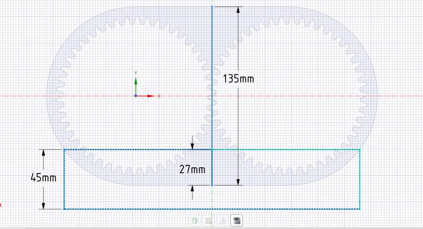
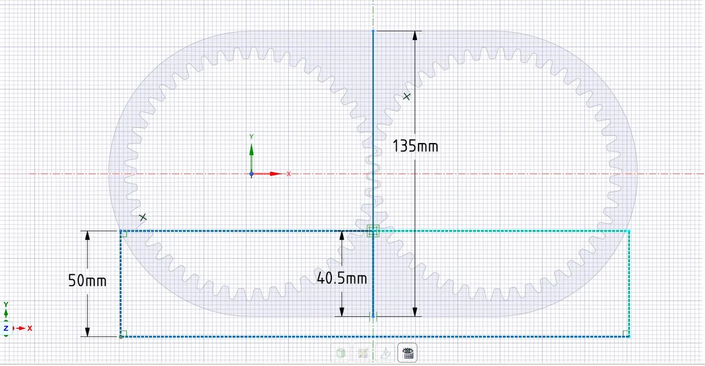
A similar approach has been done with 30% immersion. The height corresponds to 40.5mm.
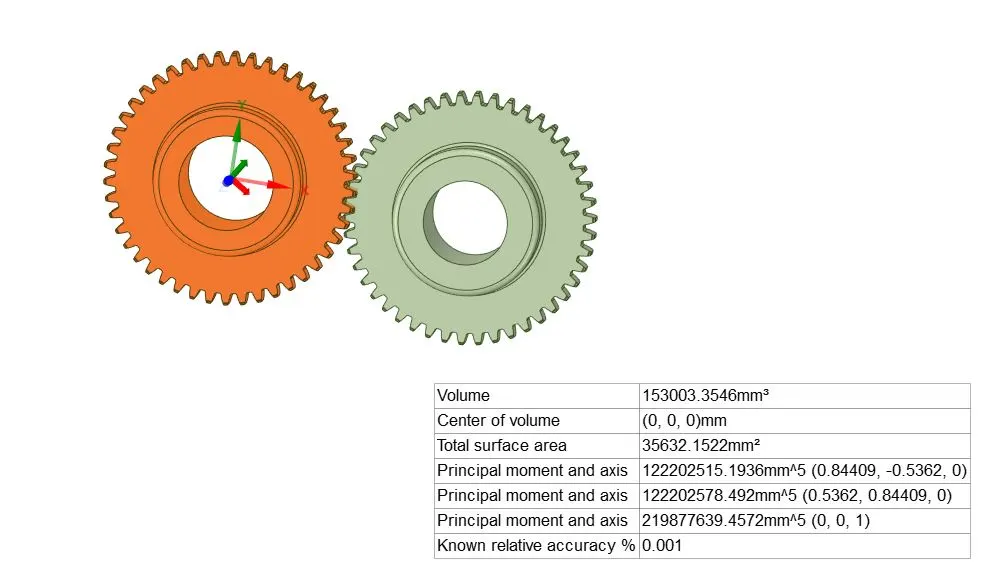
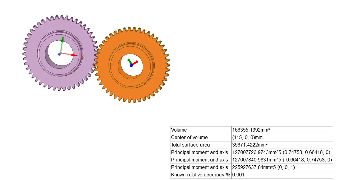
The next step is to find out the center of volume corresponding to left and right gears. From the figure the we see that the origin is fixed in the left gear, so the COV of left gear is (0,0), for the right gear, we first select the right gear>> go to prep >> select mass properties, the information is shown up.
- Open the fluent console.
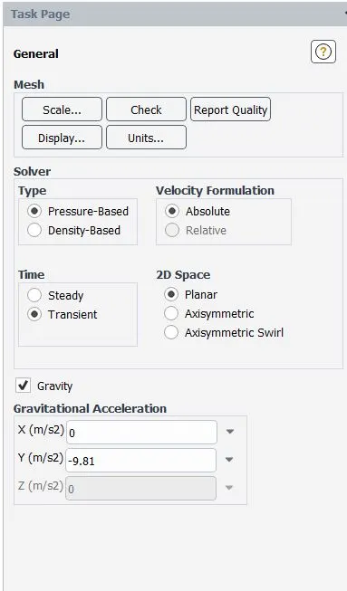
- Select pressure-based solver>> transient simulation>> enable gravitation in y axis -9.81m/s2.
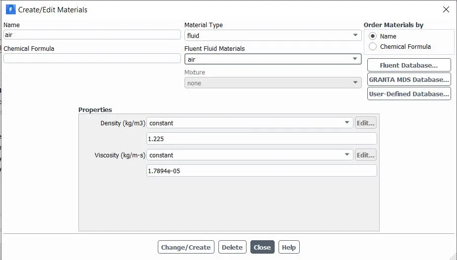
- Go to materials>> select engine oil or n heptane as required.
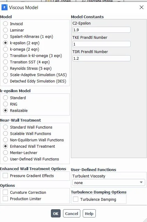
- Select viscous model from physics tab>>choose k-epsilon>> realizable>> enhanced wall treatment.
- For multiphase simulation>> select volume of fluid>> select implicit.
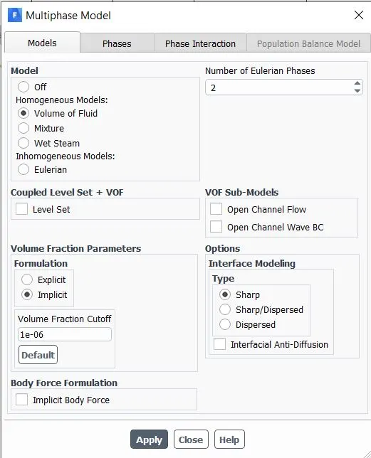
- Define the phases as primary and secondary.
- Now we define the udf function from the function tab>>click on built>>click on upload.
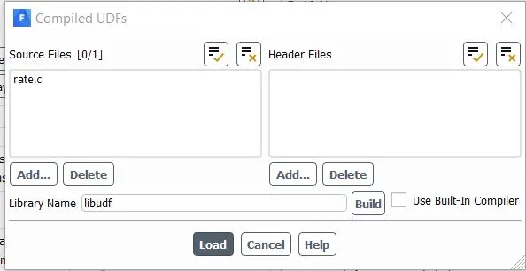
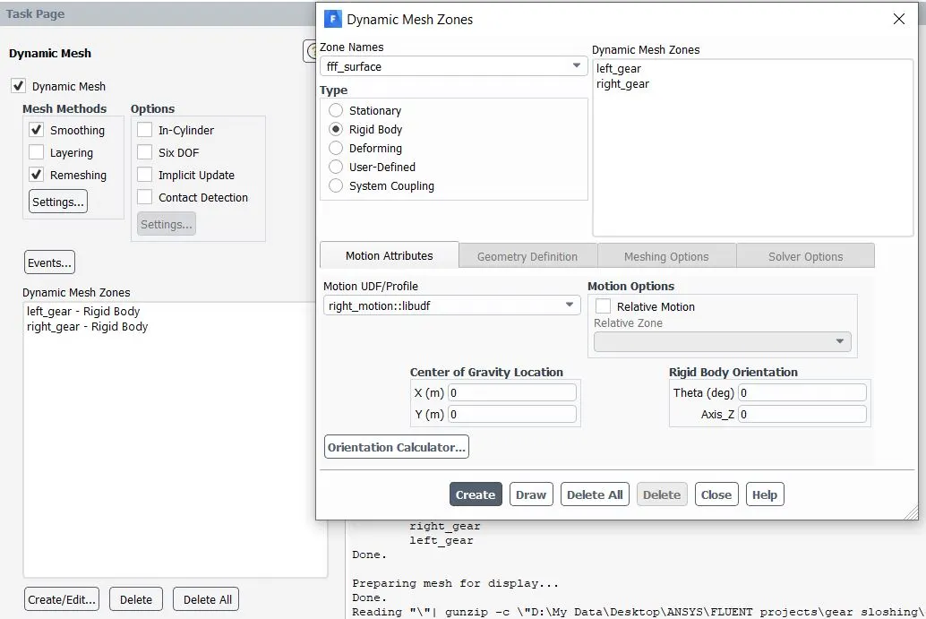
- Now activate the dynamic mesh>> select smoothing and remeshing options>> go to settings choose Laplacian layer>> go to remeshing>> select local cell size>> give the parameters like maximum, minimum length and skewness.
- Now click on dynamic mesh zones to perform rotation of the gears>> go to create>> give named selection>> specify the type of rotation>> specify the motion from the udf function>> specify the centre of gravity.
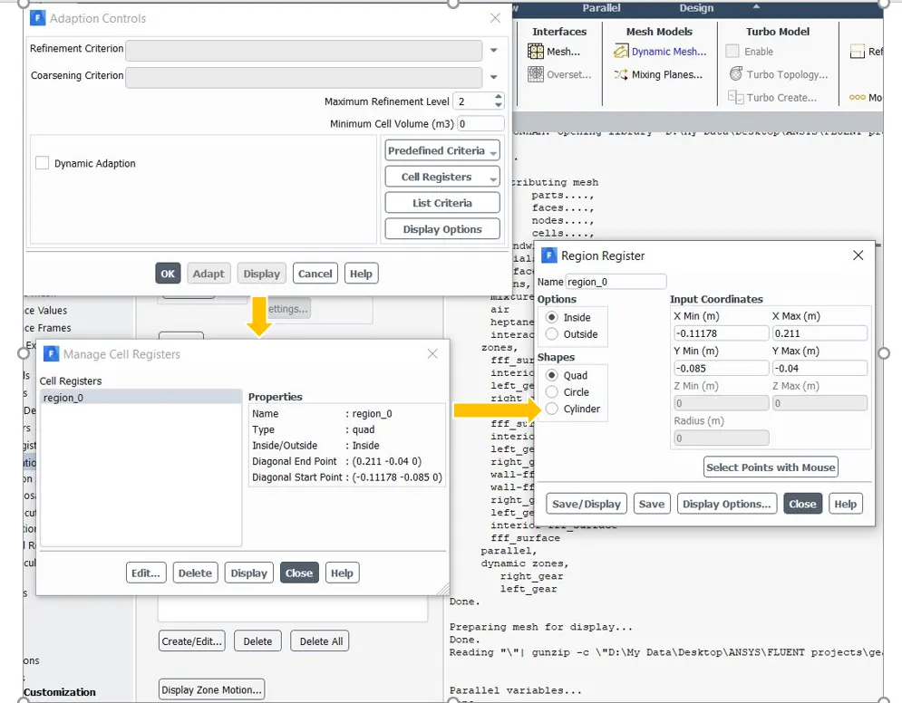
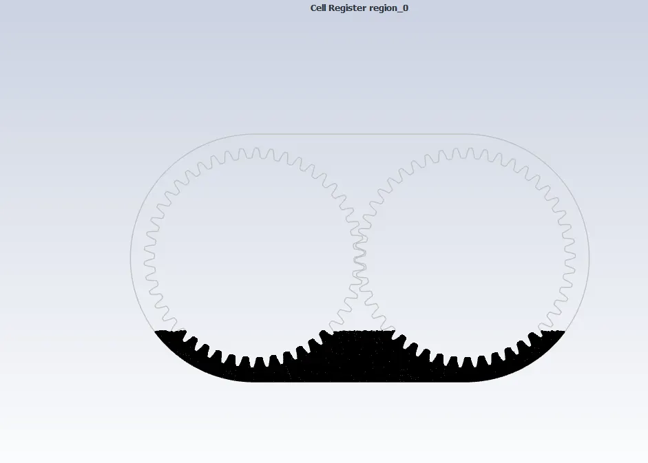
- Now we will mark and adapt the cell region up to which the gear will be immersed.
- From the adapt section>> click on refinement>> choose quad shapes>> give the input coordinates corresponding to the diagonals of the rectangle.
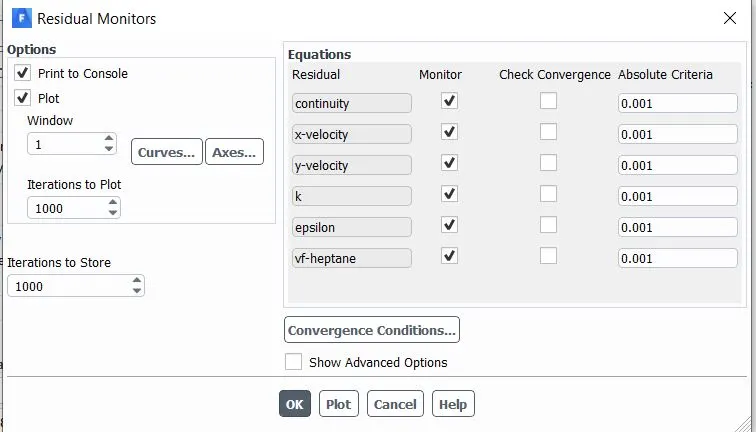
- Uncheck the convergence parameters.
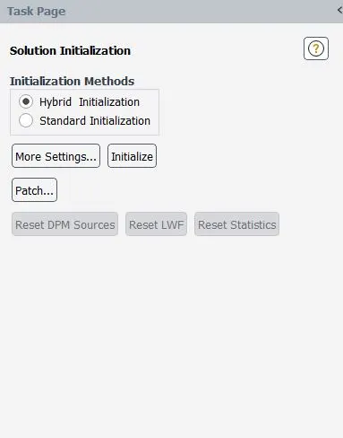
- Choose hybrid initialization.
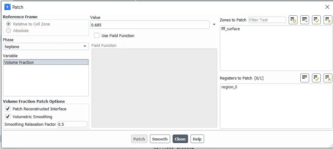
- patch the configuration from patch options
- set the time step and hit calculate.
TEST CASES
Case 1:
Details of pre-processing parameters:
Lubricating fluid: engine oil
Immersion percentage: 20%
Density:889 kg/m3
Viscosity:1.06 kg/ms
No of cell count:28327
Minimum length of cell:0
Maximum length of cell:0.001
Skewness:0.6
Solver: pressure-based solver
Starting diagonal point:(0.211, 0.040)
End diagonal point:(0.111, 0.085)
Simulation type: Transient
Turbulent model: k-epsilon, realizable, enhanced wall function
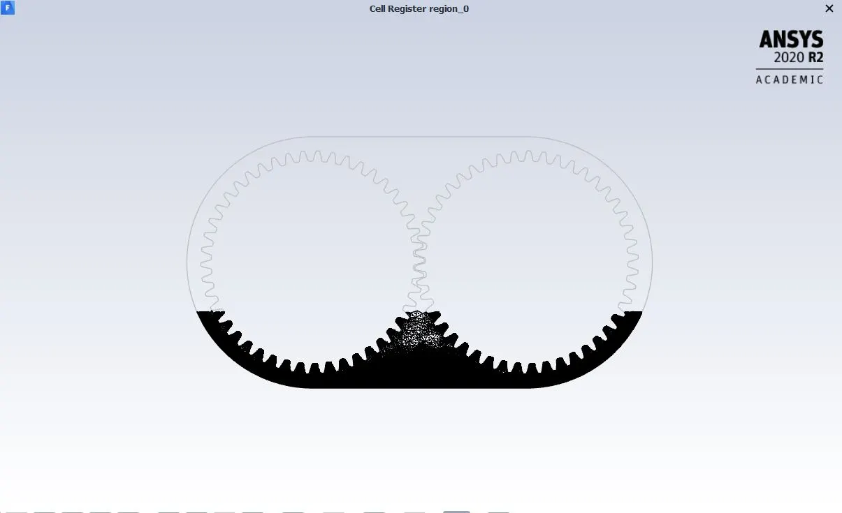
Region adaption marking zone:
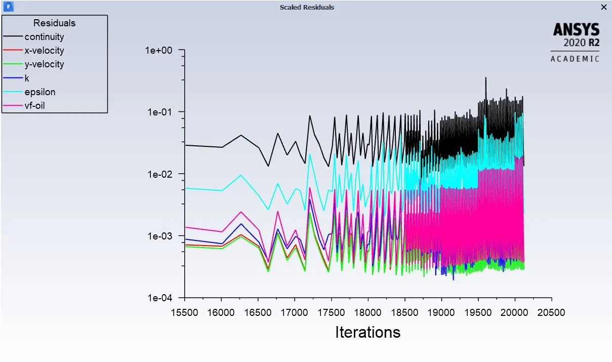
Iteration convergence:
Post-processing animations
During the initial time the lubricant (engine oil) is immersed at the bottom. The quantity of lubricant is less and the splashing helps to cover the lubricants all over the parts of gear teeth. Some loss of lubrication is observed due to lower concentration.
Case 2:
Details of pre-processing parameters:
Lubricating fluid: engine oil
Immersion percentage: 30%
Density:889 kg/m3
Viscosity:1.06 kg/ms
No of cell count:28327
Minimum length of cell:0
Maximum length of cell:0.001
Skewness:0.6
Solver: pressure-based solver
Starting diagonal point:(0.220, 0.026)
End diagonal point:(0.119, 0.077)
Simulation type: Transient
Turbulent model: k-epsilon, realizable, enhanced wall function
Region adaption marking zone:
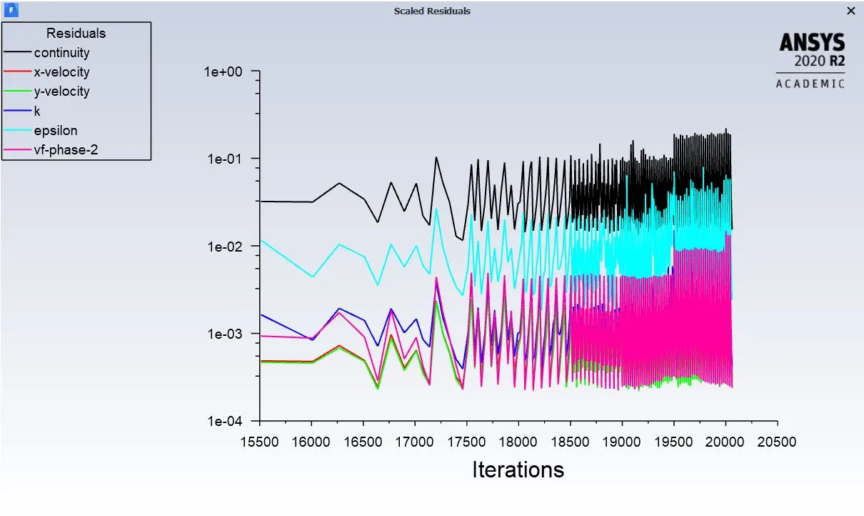
Iteration convergence:
Post-processing animations
In this case the concentration of engine oil is higher than the previous case. The splashing helps in regular distribution of oil. Since the viscosity is high, al the lubricant tends to stick to the surface uniformly.
Case 3:
Details of pre-processing parameters:
Lubricating fluid: n-heptane
Immersion percentage: 20%
Density:684 kg/m3
Viscosity:409e-3 kg/ms
No of cell count:28327
Minimum length of cell:0
Maximum length of cell:0.001
Skewness:0.6
Solver: pressure-based solver
Starting diagonal point:(0.211, 0.040)
End diagonal point:(0.111, 0.085)
Simulation type: Transient
Turbulent model: k-epsilon, realizable, enhanced wall function
Region adaption marking zone:
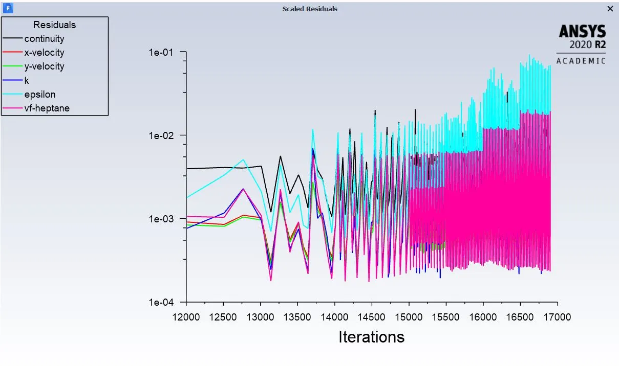
Iteration convergence:
Post-processing animations
This simulation is performed with 20% n-heptane lubricant. The lubricant is less viscous and less sticks to the surface. So a better concentration can serves the purpose.
Case 4:
Details of pre-processing parameters:
Lubricating fluid: n-heptane
Immersion percentage: 30%
Density:684 kg/m3
Viscosity:409e-3 kg/ms
No of cell count:28327
Minimum length of cell:0
Maximum length of cell:0.001
Skewness:0.6
Solver: pressure-based solver
Starting diagonal point:(0.220, 0.026)
End diagonal point:(0.119, 0.077)
Simulation type: Transient
Turbulent model: k-epsilon, realizable, enhanced wall function
Region adaption marking zone:
Iteration convergence:
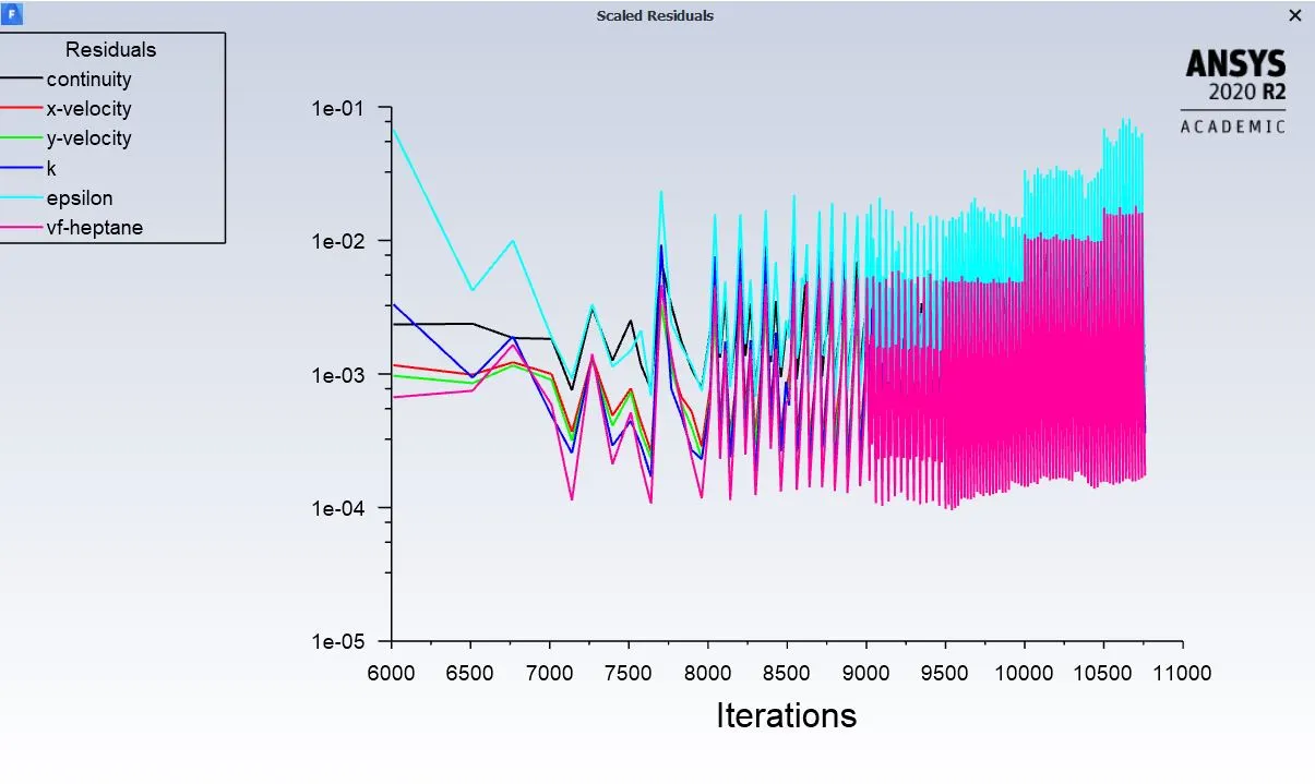
Post-processing animations
The concentration of n-heptane is higher than the previous case. In this case with a complete rotation of gears, the splashing takes place equally. A proper lubrication is seen to lubricate the gear teeth effectively.
Errors encountered during simulation run:
1. Dynamic mesh failed
This error is encountered several times due to improper selection of gear edges. Also due to unchecking of the convergence criteria, because of this the computational parameters do not converge properly at the specified points.
2.Negative cell volume detected
This problem took place because of the improper selection of the phase criteria, generally in this type of simulation, implicit schemes are more preferred to keep the courant no within limits. Another reason is improper selection of time step parameters.
Conclusion:
The four simulation with different lubricating fluid of concentration 20% and 30% is studied. At the initial time the lubricant is concentrated at the bottom. During the first rotation all the gear teeth are gaps are seemed to be filled with the lubricant with 30% concentration than with 20%. For the 20% case, the lubricants are observed to be in the state of loss of lubricant.
In engine oil case, the viscosity is higher and the lubricant tends to stick perfectly at equal gaps. Also due to rotation of gears the temperature generation gets uniformly distributed. Thus, in engine oil, the consumption of lubricant is less and less wear generation takes place.
Even though the fluid sloshing effect is completely observed in 20% and 30%, but it is completely effectively in 30%. Overall, it is seen that engine oil is preferred over n-heptane.