Challenge 9 : Project : Technical Surfacing Kia Sportage
DEVELOPMENT OF KIA SPORTAGE USING ALIAS AUTO STUDIO
Objective:
To build the car using the Curves traced from the given blueprint of the car model..
Introduction
Surface introduction
A surface, as the term is most generally used, is the outermost or uppermost layer of a physical object or space. It is the portion or region of the object that can first be perceived by an observer using the senses of sight and touch and is the portion with which other materials first interact.
Difference between SURFACES & SOLID
Surface and Solid Modeling. The area of surface and solid modeling deals with form style and illustration of physical objects. Whereas, a surface model provides solely a geometrical description of the article boundary with none topological data.
Design methodology
The step that are followed to making the concept model of the car .
- Insert the canvas image in the side plane from the import canvas option under file menu. scale it accordingly, either up or down.
- read and understand the image properly to get an idea about the shapes.
- creating different layers.
- creating the curve by using the curves and blend tools, in such case the curve has to be manipulated to the requirement of the shapes.
- Generating the surface on the curve to create the concept model of the car.
PROCEDURE:
In order to make the concept model of the car in required width and size a cube will be made with the outer dimensions of the car so that the design can be made more accurately as per requirement.
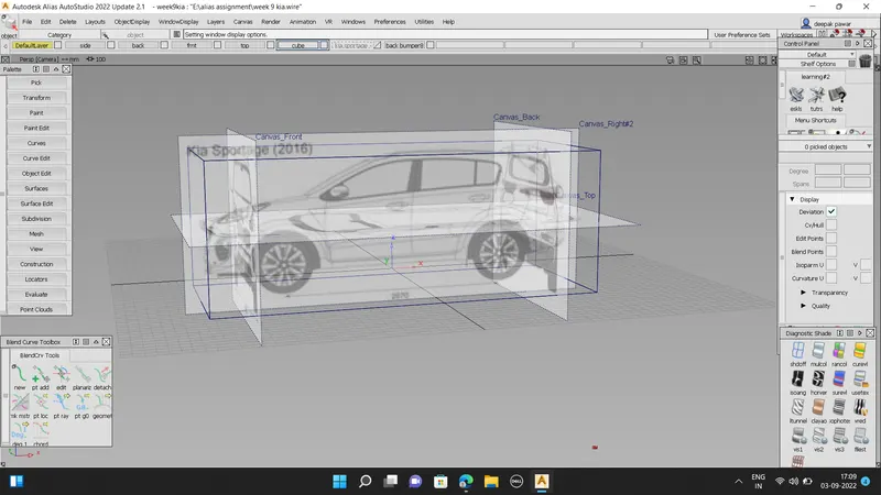
The cube with the outer dimensions of the car is made and can be seen in the above image.
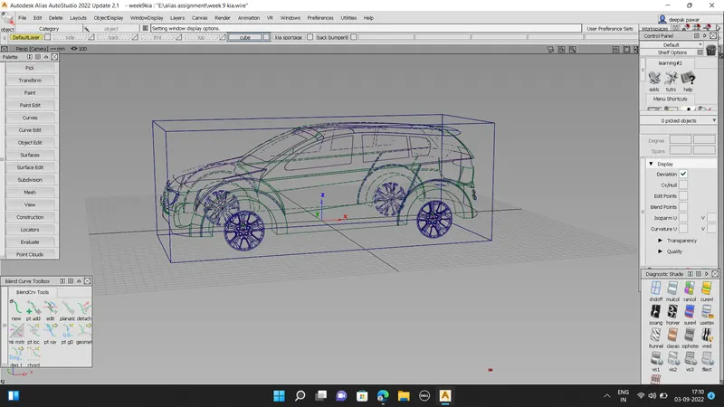
The first step in this project is to decide which views needs to imported to design the concept model of the car. As we need to design the car surface the images of the front and side views of the car will help to design the car surface.
1. Importing the front and the side view images of the car.
The image of the views will help us to build the concept model of the car.
Steps for importing Image
File -> Import -> Canvas Image -> Go
Scaling the Image:
After placing the different views in different layers the blueprints of the car will be scaled down to appropriate size so that it can be positioned accurately with respect to the other views. This will help in generation of curves at appropriate places and with desired shape of the blueprint.
Steps to scale the image:
-> Press ctrl + shift along with clicking and holding the left mouse button.
-> Select Pick object - Select the image
-> Press ctrl + shift along with clicking the
middle mouse button
-> Select Scale
-> Hold left mouse button and move up and down to scale the image larger and smaller.
Steps to move the image:
Palette -> Transform -> Move.
The image is given some amount of transparency so that the curves can be traced easily on it at required positions.
Steps to set transparency.
-> Press shift + ctrl along with clicking and holding right mouse button.
-> Select plane editor. -> Set the value of the transparency level for the different views of the image in it.
The complete image of the car with all the views is shown above.
The position of the images in the ALIAS
workbench is shown above.
2. Creation of different layers as per requirement.
Layers allow us to organize related objects into groups that you can pick, display, and edit individually or together.
Steps to create Layers
Menu Bar -> Layers -> New
The names of different layers mentioned in this project is shown below:
3. Generating the curves to trace the required shape of the front bumper.
After placing the images at required positions the curves are traced on it to give desired shape of the car:
Cv Curve- It lets to create new NURBS on the scene by placing CVs.
In order to join curves at few places blends feature is used to give desired shape.
Steps for showing blends bar
Palette -> Blend -> Blend Curve Toolbox ->
New
Curve Trim
At few places the curves are trimmed to remove curves at certain places where it is not required.
Steps to perform curve trim:
Palette -> curve edit -> crvsct
-> Select the curve -> click on "GO" present in bottom right corner -> select the curve where you want the portion of the original curve to be removed.
The curves for the half portion of the car is made as the other half is exactly the symmetry of it. The curves are made on different layer and then all the curves are assigned in this layer.
The symmetry feature is selected in this layer for the formation of the other half portion of the car.
The above image shows the curves that are made to trace of the car.
Different views of the curves.
1. Isometric view
2. Front view
4. Generating the surfaces on the curve to design the concept model of the car.
After the file in which the model of the car is being imported, the surfaces needs to be made with the help of these curves. For this purpose surface features are used which are present inside the palette bar.
The steps to use the surface generation features are:
Windows -> Palette -> Surface
By following the above procedure the surface generation features can be used.
Few of the surface generation features that
were used in this project is listed below:
1. Square
2. rail
3. skin
4. ffblend
1. Square:
Steps to go to square feature:
Windows -> Palette -> Surface -> Square
Square feature creates surfaces by blending four boundary curves (or curve segments), while maintaining continuity with adjacent surfaces.
Free Boundary - This edge is free to move if required by another edge's continuity or by the Influence sliders (see below). This is the default.
GO Position - Keep this edge exactly like the boundary curve that created it. In other words, do not let the edge move as with the Free option. This is equivalent to positional continuity.
GI Tangent - Try to keep tangency with a surface that shares this edge.
G2 Curvature - Try to keep curvature continuity with a surface that shares this
edge.
Implied Tangent - Try to keep tangency with an implied surface that shares this edge. The implied surface is the surface that would be created by mirroring the new surface. (The way the Square tool tries to keep tangency with an implied surface is by blending the slopes of the boundary curves.)
This is a powerful feature. It lets you model one half of a symmetrical surface (such as a car body), and maintain continuity at the seam. When you duplicate the surface to create the other half, the seam will already be continuous. For this to work across a symmetry plane, you must make sure the ends of the curves are tangent across the symmetry plane (that is, the tangents are perpendicular to the symmetry plane).
Implied Curvature - Try to keep curvature continuity with an implied surface that shares this edge. The implied surface is the surface that would be created by mirroring the new surface.
2. Rail
Steps to go to rail feature:
Windows -> Palette -> Surface -> Rail
Rail feature creates a surface by sweeping one or more profile curves along one or two path curves (rails).
The Rail Surface tool takes its name from its use of one or two "rail" curves. The generation curves maintain contact with the rails at the same points through the sweep, like a train traveling on a track.
The Rail Surface tool is similar to the Extrude tool, but has many more options and much more power.
The appearance of the Rail Surface icon depends on the Generation Curves and Rail Curves settings in the Rail Surface Options window.
3. Skin
Steps to go to skin feature:
Windows -> Palette -> Surface -> Skin
Skin feature is used to create a surface by connecting a set of profile curves.
4. ffblend - Freeform blend
Steps to go to ffblend feature:
Windows -> Palette -> Surface -> ffblend
Free form blend enables us to create a transitional surface by selecting two input contact lines. These input contact lines can be surface curves or free curves.
To edit the surface, surface edit tools areused to obtain desired shape.
The various surface edit tools used to give desired shape to the surface is shown below:
1. Project
Steps to go to Project feature.
Windows -> Palette -> Surface Edit -> Project
This feature is used to create curve on surface of the existing curve which will be projected on the selected surface.
This is like shining a flashlight at the curve, and turning the shadows on the target surfaces into curves-on-surface. The line between the flashlight, the curve, and the shadow is the projection vector.
- Trim
Steps to go to Trim feature:
Windows -> Palette -> Surface Edit -> Trim
Trim tool trims or splits surfaces using curves-on-surface or cross sections.
In order to use the trim feature first the curve is projected on to the surface and then trim is clicked, after clicking on this tool the surface that we want to keep is clicked.
After selecting the surface that is required from the original surface we need to select keep and then the unwanted surface will be removed to get desired shape of the surface that we want to have.
Surfaces for different portion of the car are generated in different layers and then symmetry feature is selected to obtain the surfaces on both the sides.
Object edit features:
1. Align
2. Extend
- attach
4. Detach
1. Align
Steps to go to align feature:
Windows -> Palette -> Object Edit -> Align
The Align tool moves or reshapes a curve or surface to achieve positional, tangent, or G2 curvature continuity with another curve or surface, and it offers G3 curvature continuity. It also provides a simplified interface, direct interaction through the use of manipulators, and superior output, compared to the Align 2008 tool.
2. Extend
Steps to go to extend feature:
Windows -> Palette -> Object Edit -> extend
Extend tool is used to add to an existing curve or surface by extending from an endpoint or edge. You can extend straight out or continue the curvature at the endpoint or edge.
You can also extend a trimmed surface if the Merge option is turned off, and you selecta boundary which is a surface isoparm (constant U or V). You cannot select a trim edge.
3. Attach:
Steps to go to attach feature:
Windows -> Palette -> Object Edit -> attach
The attach feature is used to combine two surfaces together.
3. Detach:
Steps to go to attach feature:
Windows -> Palette -> Object Edit -> detach
The attach feature is used to separate two surfaces with the help of curves on surfaces.
Diagnostic Shade:
Diagnostic Shade feature allows us to shade the model using various modes. Steps to show this tool:
Windows -> Diagnostic Shade
Purpose of using Diagnostic Shade feature:
1. Show the minimum and maximum curvature on a surface
2. Shade surfaces with color
3. Annotate a model or cloud data
The icons under Shading shade your geometry so you can view and evaluate your surfaces. The various shading modes provide
different diagnostic information about surfaces.
Some tools in diagnostic shading, such as Horizontal/Vertical, simulate light reflecting against the surface of your model. Reflecting light on a surface is a good way to check for any bumps, dents, or other irregularities. Reflections also point out any surfaces that do not meet smoothly.
Few of the shades used to check the surface is shown below:
1. shdnon
Full form - shading off diagnostic shader
The wireframe model appears with no shading. This icon clears the wire model of its current shading. No options are available with this shading mode.
2. Mulcol
This shade helps to colour the surface generated with a single colour. This helps us to identify the places where the surfaces are generated and where it is needed to be generated. It also helps to identify the dents, bumps, and other surface irregularities.
3. Horver
Horizontal/Vertical highlighting helps you find surface flaws. A common use for this is the identification of adjacent surfaces with mismatched tangents-in other words, surfaces that do not meet smoothly. You can also use Surface Continuity for this purpose, but Horizontal/Vertical highlighting gives you a clearer view of the surfaces.
This mode lets you sweep a multiple black and white highlights across a surface. You can see where the highlights do not move smoothly. A jump in the highlight flow indicates flaws in either the surface or its boundary with a second surface.
The different surfaces created at different portions of the car in different layers is shown below, the surfaces can be seen with the help of mulcol feature in diagnostic shade.
After completing the generation of surfaces with the help of features in surface, surface edit, object edit, etc, the complete concept design of the bumper is generated.
The above image shows the complete concept design of the front car bumper.
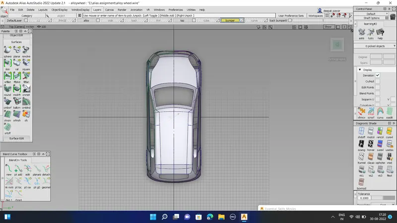
Final views of the car front bumper.
1. Isometric view.
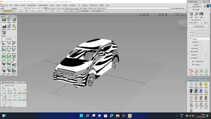
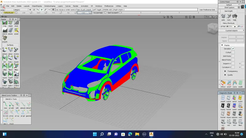
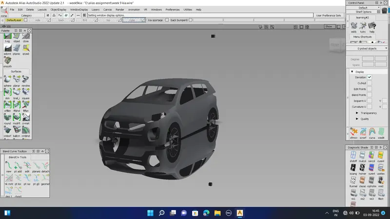
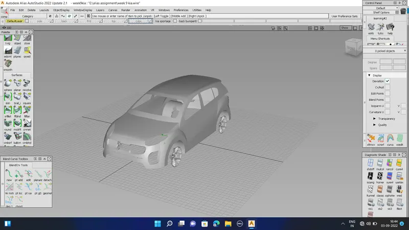 2. Front view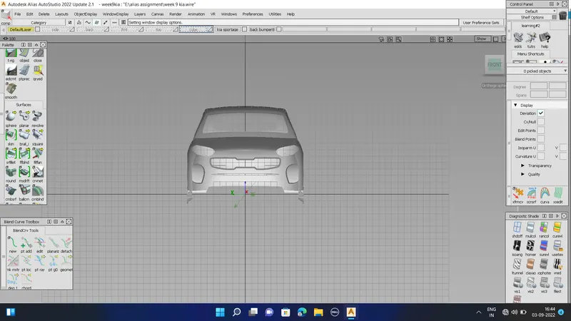
3. Top view
4. Side view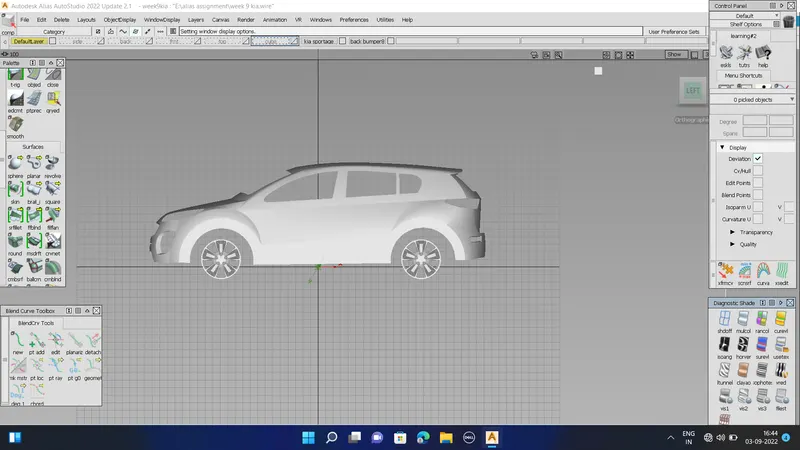
CONCLUSION
Using the knowledge of previous weeks, we were able to make a good surface model of KIA SPORTAGE car.