Challenge 7 : Concept Modelling of Steering Wheel
Concept modelling of steering wheel
OBJECTIVE: To make a model of steering wheel from one image by visualization.
INTRODUCTION: Concept modeling is modeling where 3d data starts to take shape. It is a crucial part of the process as every part involved in the design process depends on this to actually visualize, how the design has come out, the shape and feel of it. This process starts from the point where the design has come up to a point of finalization.
The entire car or model is not designed by a single member of a team rather it is divided into parts and distributed among the team members to part by part. In this project we are modeling a steering wheel using a single image. Many a times, things has to be visualized by the designer which helps him to get an idea of the model would look from other views and thus complete the model. As only one view is present here, we may have to take help of three quarter view for the details which cannot be seen in this image and also some things have to think about, like h the flow of the surface would be. Thus this model will help in increasing the knowledge in visualization.
DESIGN METHODOLOGY:
- The steps that are followed to design the concept model of the front steering wheel is shown below through flowchat.
- Deciding which views are required to make the steering wheel and importing the necessary view
- creating different layers
- generating the curves to trace required shape of the steering wheel.
- generating the surface on the curves to create the concept model of the steering wheel.
- final views of the front steering wheel.
DESCRIPTION:
- CV curves under curve toolbox option in
the palette. CV curve tool is used to make curve. This is one of the primary tools available for the users to make any desired shape.
ep curve tool can also be used for similarly.
- Blend curve toolbox This tool is used to blend two curves to make the corners round so that the resulting curve is proper and continuous.
Further edit tool in the same toolbox enables the user to manipulate the blend curve to a desired shape.
3.Object edit toolbox: tools used under this are
- Extend tool: it is used to extend or reduce the size of the curves.
- Query edit tool: it is used check and vary the construction history of a surface.
- Detach tool: it is used to detach say a part of a curve or surface from the rest of the shape.
- Align: it is used to align two surfaces wit each other according to their position ( requirement.
- Surface toolbox:
The most important toolbox for surfacing is this toolbox. It has various tools for the user to make a surface. A surface can be made by using different tools according to the requirement of the user. The used ones in this model are listed below:
- Skin: used between two curves to make a surface.
- Rail: it is used to a make a surface by
assigning generation curves and rail curves. 3. Square: four curves in continuity are
necessary to make this surface.
- Planer: it creates a planer surface for a
closed curve.
- Free form bend tool: this makes surface between chosen curves.
- Surface fillet tool: it blends the edges of the two surfaces and makes it soft.
- Surface edit toolbox: this tool box is used to edit the surfaces when required. Used tools are listed below:
- Project tool: this is used to project a curve on a surface which is necessary to further use trim command.
- Intersect tool: this tool is used to create am intersection between two surfaces whi further used to trim the surfaces.
- Trim tool: it deletes the unnecessary part from a surface.
- Untrim tool: it undo the trim tool.
- Trim convert tool: it converts the patch of a surface and creates a new surface. 6. Diagnostic shading
It can either be accessed from the control panel or from object display option in the upper toolbox. This has various shading option for the user to check the continuity of the surfaces created. Commonly used diagnostic shaders are:
- Shading off listed as shdnon. 2. Multicolor listed as mulcol.
- Horizontal/vertical listed as horver.
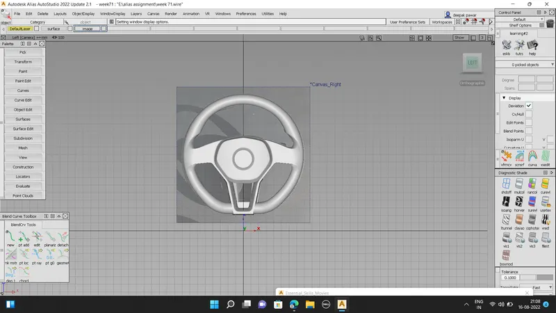
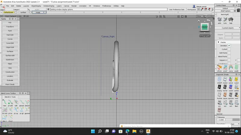
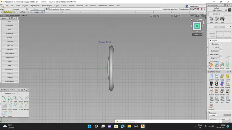
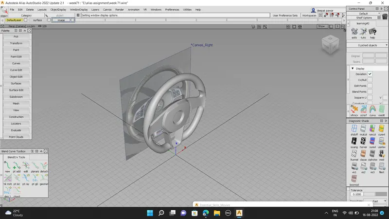
IMAGES
FRONTVIEW;
SIDEVIEW:
TOP VIEW:
ISOMETRIC VIEW:
CONCLUSION:
The complete concept modelling of the steering wheel is designed with the help of first tracing the curves on the image of the front and side views of the steering wheel