Challenge 8
1. Pier is a structural element which transfers the loads from pier cap to the foundation. It is a compression member. This subjected to axial force and shear forces. This is also subejcted to bi-axial moemnts. The loads considered for total design force are as follows:
a. Dead Load - Load due to self weight of Girders, pier cap, pier
b. Superimposed Dead Load(SIDL) - Load due to Track plinth, rail, cables, cable trays cable troughs, handrails, parpets, OHE posts etc
c. Live Loads - Load due to the metro rail/rolling stock running on the superstructure. This load is vertical load due to live load. Other loads due to live load are braking loads, traction loads, centrifugal force and derailment load
d. Wind Loads- Wind Loads coming on the structure. This can be applied in 2 cases, when high intensuty winds are there then live load may not be considered and under noraml wind pressures wind load shall be applied along with live load.
e. Earthquake load - These are the loads due to seismic activity. These are coming in longitudinal, transveres and vertical direction also. In case of longitudal seismic case the mass of live load shall not be considered as the live load rolls/slides on the rail and there is no interaction of this mass with ground motion to induce seismic force.
f. LWR Force (Long welded rail force)- The rails of metro are provided with rail expansion joints at very large distances as compared to the spans of the viaduct. Hence this long rail is bound to undergo thermal contraction and expansion which inturn induces the forces in the substructure. These forces are generallly derived from Rail Structre interaction study which considers the stiffness of all the structural element like rail (UIC60), bearing, pier cap, pier foundation etc which are involed in interaction of long rail.
g. Derailment Load - This is load which is accidental in nature and can occur if the metro derails from the track. This can then slide to the edge of the superstructe or even topple and apply load to flange or u-giders or parapets of other types of superstructure.
2. The major loads coming on to the pier are DL, SIDL & LL. The details of the same are as below:
a. Dead Load - Load due to self weight of Girders(superstructure), pier cap, pier are the loads which are to be considered in the design of pier. These loads are applied as gravity loads on to the pier and also contribute to the seismic force as a mass.
b. SIDL - These are superimposed loads mostly on the superstructre which are considered in for calculating the forces on pier. These are due to Track plinth, rail, cables, cable trays cable troughs, handrails, parpets, OHE posts etc. These load may not be assess with good accurany and hence for design load calcuation a higher factor as compared to the dead loads on girders, pier cap, pier are applied to this load.
c. LL - This load is due to the metro rail/rolling stock running on the superstructure. This load is vertical load due to live load.
The vertical loads are considered in 4 different case of loading on the adjacent spans of a pier.
i. OTOS- One Track one span loaded. Induces Axial force and being moement in both the directions in pier
ii. OTBS one track both span- Induces axial force and bending moment in transver direction. The moment in longitudinal direction are low or zero if adjacent spans are different or same respectively.
iii. BTOS Both track one span - Induces axial force and moment in longitudinal direction. The moment in transver direction is nulliefied.
iv. BTBS Both track both span - Induces maximum axial force. The moment in tranvserse direction are nullified. In longitudinal direction the moment are low or zero if adjacent spans are different or same respectively
The load due to braking of rail are braking forces and are considered at 18% of the unfactored vertical loads
The loads due to traction of rail for starting the movement are tractive forces and are onsidered at 20% of the unfactored vertical loads
The centrifugal forces in the curved stretches of the viaduct are calculated based on the radius and the maximum speed for given radius. The limiting speeds for giving radius are specified in the DBR.
Coefficient of Centrifugal Force =( V^2 )/( 127 R ) (V is maximum speed in km/hr & R is radius in m)
The grade of Cement used in pier can be 53 Grade OPC cement. The Grade of Concrete used for Piers in generally high strenght concrete ranging from M50 To M60 grade.
3. The load due to braking of rail to reduce the speed or to bring the rail to halt are braking forces and are considered at 18% of the unfactored vertical loads
The loads due to traction of rail for starting the movement of rail or increasing the speed of the rail are tractive forces and are onsidered at 20% of the unfactored vertical loads
The critical combination of braking & tractive forces in design of pier is when Braking is applied on Up-Track and Traction is applied on Down-Track. This induces the maximum design effect due to these forces.
4. The centrifugal forces occur in the curved stretches of the viaduct. These are calculated based on the radius and the maximum speed for given radius. The limiting speeds for giving radius are specified in the DBR. The maximum allowable speeds are reduces in the sharp radius stretches of the viaduct.
Coefficient of Centrifugal Force =( V^2 )/( 127 R ) (V is maximum speed in km/hr & R is radius in m)
The mass of the live load is applied to by Coeff. of Centrifugal force the derive the Centrifugal force. This induces shear force & bending in pier in transverse direction. This force is applied at CG of the rail which is generally considered at 1.8m above the rail.
Wind loads are the effects of wind on the metro structre and also on the live load ie the metro rail running on the metro viaduct.
These are generally considered in 2 cases as below:
a. Wind Load without Live Load - This case is considere when the wind intensity and wind pressure are very high. In such cases the movement of train on the track in difficult and the metro train are generally halted at stations. In such cases, for design of substructre the live load in not considered and the wind load of severe intensity are considered for design checks.
b Wind Load with Live Load - This case is a general operation case for the metro. The metro trains are running on the viaduct and the normal wind pressures are considered to be applied on the viaduct structure as well as the train.
5. Earthquake load - These are the loads due to seismic activity. These ocuur in longitudinal, transveres and vertical direction also.
Longitudinal Seismic Load - In case of longitudal seismic case the mass of live load shall not be considered as the live load rolls/slides on the rail and there is no interaction of this mass with ground motion to induce seismic force. In this case seismic load due to superstructure, piercap pier are applied on the pier for design.
Transverse Seismic Load - In this case the live load in restrained from movement in transverse direction and hence contributed to the seismic load along with masses of Superstructure, pier cap, pier. The live load considered in this case is reduced in load combination as the probabily of occurance of design live load and design seismic activity at the same time is very low.
Vertical Seismic Load - This is the load in vertical direction, due to vertical ground motion during seismic event. These can add to axial forces in the substructure.
The time period of the pier structure idealised a SDOF is calculated. Based on this time period and the type of ground Sa/g factor is taken from the code. Then Ah=Z/2 x I/R x Sa/g. This Ah is then multiplied to all the masses contributing in partilcular case and the design forces are derived.
The seismic cases for combination of forces in 3 direction are considered as below
a. 1.0 Longitudinal + 0.3 Transverse + 0.3 Vertical
b. 1.0 Transverse + 0.3 Longitudinal + 0.3 Vertical
c. 1.0 Vertical + 0.3 Longitudinal + 0.3 Transverse
6. LWR Force (Long welded rail force)- The rails of metro are provided with rail expansion joints at very large distances as compared to the spans of the viaduct. As this long rail is bound to undergo thermal contraction and expansion which inturn induces the forces in the substructure. These forces are generallly derived from Rail Structre interaction study which considers the stiffness of all the structural element like rail (UIC60), bearing, pier cap, pier foundation etc which are involed in interaction of long rail.
UIC 774-3R specified the provisions for calculation of LWR forces by carrying out Rail Structre Interaction. The parameters considered for this study are i. Track Resistance in Loaded & Unloaded conditions ii. Maximum additional stresses in rail in tension as well as compression iii. Maximum delflection of girder at ends
Derailment Load - This is load which is accidental in nature and can occur if the metro derails from the track. This can then slide to the edge of the superstructe or even topple and apply load to flange or u-giders or parapets of other types of superstructure.
The Appendix XXV of the BRidge Rules provides the guidelines for the load application for this case. The strength check for ULS provide The load at which a derailed vehicle shall not cause collapse of any major element. The stability check is specified to avoid overturning of structure under derailment load.
In metros, additional check as per Sacramento Derailment Criteria is also required. This criteria specified application of 40% of one coach weight applied horizontally as a 3m long uniform impact load on top of ugirder flange or deck slab.
7. The load combinations for the deriving the design loads for structural elements are prepared based on the probability of occurance of various loads at same time. The probablility of occurance of ultimate loads of various cases at the same time and hence they are not directly added with each other. Either such combinations are ignored or the value of one of the loads is reduced appropriately. With this consideration the load combinations are categorized in following groups:
G I - This group considers the noramal loads we are present on the structure for most of the time. This group inloves Dead Load, SIDL, Pre-stressing & Live Load as main loads.
G II- This group considers the combinations of variable loads. The variable loads are Live Load, Earthquake Load, Temperature Load, Wind Load. In this case, if one varible load is considered at its ultimate value then the value of other load is reduced appropriately. For example, in case of earthquake combination(GIIb) live load factor is 0.5.
G III - This group considers the combinations for temperature effetcs on the structure.
G V - This group is for consideration of derailmenet loads.
Based on the principles of various groups stated above the load factors of SLS & ULS combinations are specified in the code.
In case of ULS combinations the G III load case is not to be considered as per CL.10.3.1 of IRS CBC.
This can be because ,in case of ULS events the structures undergo large deformations.
The loads or stresses coming from thermal effect which are based on deoformation can be dissipated due to large deformations under ULS loads.
8. SIDL loads are due to Track plinth, rail, cables, cable trays cable troughs, handrails, parpets, OHE posts etc.
These load may not be assessed with good accurany and hence for design load calcuation a higher factor as compared
to the dead loads on girders, pier cap, pier are applied to this load.
The overlay of roadways after many years is one such example where there can be considerable variation in the predicted load.
9. Following are the basic design parameters consdiered for the design of RCC pier cap.
Load: Bending Moments, Shear Force for SLS and ULS Combinations at all the sections to be considered for design checks
Material : Grade of Concrete, Grade of Reinforcement Steel
Cover Requirements based on Exposure conditions
Allowable Crack Width based on Exposure Conditions
10. The typical detailing of reinforcement in RCC cantilever pier cap is explained as below:
Typical Reinforcement in Section of Pier Cap:
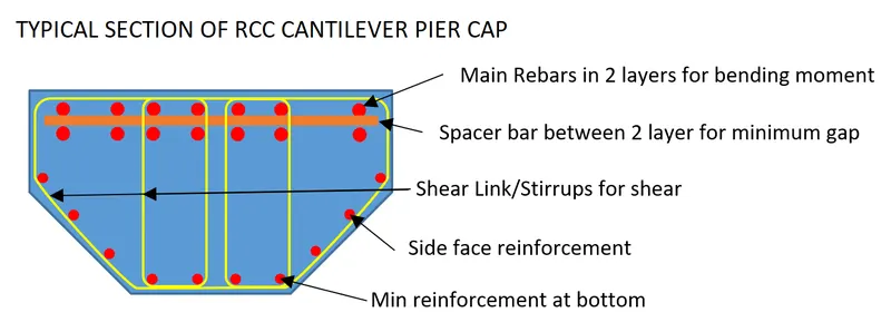
The section reinforcement involes following elements:
Main Reinforcement for Bending moment which can be in one layer or multiple layers based on the benidng moment in the section. In case of multiple layers, a spacer bar is provided between 2 layers to ensure minimum space between two layers of bars. The dia of spacer bar shall be more than the min. bar dia of the two layers adjacent to the spacer bars.
Shear Links/Stirrups are provided to resist the shear load on the pier cap.
The side face reinforcement is provided to encase the concrete and provide better resistance to compression in the concrete core.
The minimum reinforcement is provided in the bottom since there are no active tension forces in bottom layer of a cantilever pier cap.
Typical Reinforcement in Elevation of a RCC Cantilever Pier Cap:

The 1st layer of main reinforcement for cantilever pier cap is provided as a closed loop to ensure proper anchorage to the tension in these bars. The other layers can be provided with spacer bars as shown in the sketch above.
Shear Link/stirrups are provided at a spacing as per the design requriemement. In case of cantilevers with varying depth these link have varying depth as per variation of cantilever depth.
Side face reiinforcement is provided as shown in the sketch to confine the core concrete.
The minimum reinforcement is provided at the bottom suitably.
In case of crobel type of pier caps, confining reinforcement in both the direction is provided to avoid failure by crushing of compression strut.
As the moment from pier cap is to be transfered to the pier effectively, continuity reinforcement from pier is extended in the pier as shown above. For the same reason, anchorage reinforcement from pier cap is also extended in the pier as shown above.
The bars in the region of drainage pipes or other similar items shall be adjustes as per site requirement with out reducing the total reinforcement specified in given section.