Challenge 2
1. The structural Components of a Bridge
a. Superstructure - THe structure which connects two piers of metro rail system. This is a small span bridge. THe types are I-girders, Box Girders, U girders, Composite Girders etc. The type can be choosen based on the span.
b. Bearing - These are elements which connect the superstructure with substructure i.e. pier cap and pier. Types are Elastomeric, Pot PTFE, Spherical. The type can be choose based on spans. Elastomeric bearing are most effective and commenly used in metro.
c. Substructure - Pier cap and pier are part of substructure. These transfter the loads from superstructure to foundations. Types are circular pier, rectangular pier, Cantilever pier caps, portal system. Rectangular piers are more efficient. The circular pier can be more efficient in water chanels.
2. The superimposed dead loads are the loads on metro structure other than the self weight of superstructure girders. It includes mechanical, electrical and plumbing cables,lines etc and related fixtures etc. The Over head electric cable and noise barriers are also part of SIDL loads. The fixed SIDL can be applied with load factor same as that for deal load of superstructure however variable SIDL shall be applied with load factor for SIDL. These variable load factor may vary during the lifetime of the metro bridge.
3. Different types of girders- a. Pretensioned I girders b. Posttensioned I girders c. Pretensioned U girders d. Segmental Box Girders e. Steel Concrete composite I girders f. Steel Open Web girders e. Steel Truss girders
The type of girders are chosen based on the spans, construction equipments, project timeline, method of construction and overall economy of a given type.
4. The bearings in a metro viaduct system are structural elements which connect the superstructure with the substructure and transfer the forces from superstructure to substructure in flow path as desired by designer.
Types of Bearing-
a. Elastomeric Bearing - These are bearings made with steel reinforcement and elastomeric pads. These are most economic solutions for standard metro spans. These can be easily replaced after end of thier service life.
b. POT-PTFE bearing - These are bearings made of reinforced elamstomers fixed in steel casing for confinement. These are used for loads higher that standard elastomeric Bearing.
c. Spherical Bearing - These bearing are made with steel elements and use PTFE sliding elements to cater for rotations and translations in the superstructure. These are used for superstructure with higher spans around 80m-100m. The higher spans result in higher loads and rotations. The spherical arrangement with PTFE efficiently allowas the higher rotations.
5. Topographical details to be considered while constructing metro viaduct over water passages
a. Ground levels of area on the alignment
b. Water levels and Highest flood levels
c. Bed levels of river on the alignment
d. Levels and details of any existing structure or bridge near alignment
e. Details of any navigation channel and related clearance requirements
6. Types of Girders in metro viaduct:
a. I girders - These girders can be pretensioned or posttensioned. They are used in very sharp curvatures and longer spans where U girder or Box girder may be difficult to design.
b. U- girders - These are precast U/C shape open web sections made in concrete. These are generally pre-tensioned. They are light and efficient section in case of spans around 25m-27m and without sharp radius in alignment. These being open web sections are not preferred in curved alignment which leads to torsional loads in the deck. They are easily erected with help of cranes and are most preferred type of superstructure due to fast erection speed in metro projects.
c. Segmental Box Girders - These are box section generally with singel cell. They are used for spans around 31m-34m. They are erected with group supported stage or launching gantries based on space availability at site and construction timeline. These are cast in segments at casting yard and are glued with epoxy and erected at site. They are torsionally stiff and perform well in curved alignments and torsional loadings.
d. Steel Concrete composite I girder - These are composite girders which are made by casting concrete deck on steel I girders. These are adopted for spans around 40m-50m. The steel girders can be erected with ground support or can also be erected using cranes.
e. Open web girders - These are steel trusses which are used for spans longer than the above other types. These are structurally efficient systems for long spans.
7. The advantages of U-girders for being the choice of metro designers in India:
a. U-Girders are economical and efficient for pre-casting of standard spans 25m-27m. These are light structures and help in reducing the dead load. Pre-casting of girders provides improved quality control as compared to cast-in-situ construction. Due to pre-casting the erection at site and casting at casting yard can done simultaneously to speed up the construction.
b. The erection of U-girders being lightweight can be done with help of cranes or launching gantries. In populated cities traffic diversion and planning during superstructure erection is major challenge. U-Girders are transported during night time when traffic is low. At site they are then erected with help of launching gantries or cranes. This speeds up the process of girder erection. For erection of 1 span only 2 lifts are required however in case of segmental construction or I girders the lifts are more and also there is cast-in-situ deck or epoxy gluing of segment which are additional time consuming activities.
c. The shape of U-girders also helps in noise control in urban areas of metro corridors.
8. Open Web Structures are the structures in which the webs of girders are open. That means the webs are not completely connected with flanges to allowa for continious shear flow thorugh the section. The U-Girders used for Metro are one type of Open Web Girders. These are effient structures for sapns around 25m-27m as they are economical for this range. They are also light weight and satisfy all the functional requirement sof a typical metro viaduct system. They can be easily erected with cranes during night time since they are light structures.
9. The load flow behaviour of Open Web Girder - U-Girders can be classfied in 2 Different types.
a. Local Transverse Behaviour -
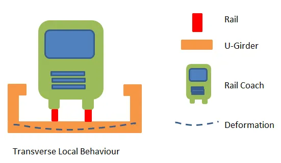
In this case the load of Axle/Rail Coach is transferred from Rails to the global girder structure or webs of U-Girder by transverse bending of soffit. The defoemation of soffit is as shown in the sketch above. The soffit also has to deform in longitudinal direction to cater for global bending in span and hence the deformed shape of soffit can appear as saucer.
b. Global Behaviour - The loads from Rail Coach are carried through soffit and are transferred to the webs and complete section of girder for global bending.
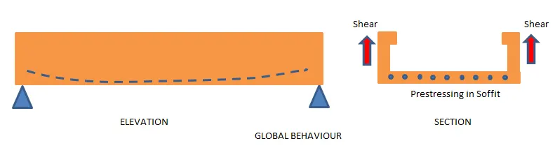
The shear is resisted by the two webs. The bending moment is resisted by soffit and flanges at top of both webs. The pre-stressing provided in the soffit slab generates compression in soffit which help is resisting the tension arriving in the soffit due to dead loads and live loads.
10. The Table No.11 of IRS CBC Code provide the limitations for Serviceability Limit State for various materails.
The compressive stress limitations for RCC in case of Traingular stress due to bending are 0.5 fck and the same for PSC are 0.4 fck. For Uniform compressive stress in case of axial loading are 0.38 fck for RCC and 0.3fck for PSC.
The compressive stresses in RCC structures arise due to the external loading such as dead loads, live loads and hence these can reach their limits in case when the bridge is subjected to its maximum design loads. However in case of PSC structures the compressive stresses are generated due to pre-stressing force and are bound to arise as per applied pre-stress. These are reduced when dead load or live loads are applied. Hence considering these details and the chance of attainment of stress levels in RCC & PSC structres a higher allowable stress is specified for RCC structures and lower stresses for PSC structres in case of concrete.
The allowable stress in case of flexural stresses(0.5fck-RCC) are higher as compared to that for axial stresses(0.38fck-RCC) since in case of flexural stress the triangluar distrubution leads to average stress in section lower than the limiting value and this ensure some reserve capacity in the section. However in case of Axial Stress and rectangular stress distribution the average stress is same as limiting stress and section has no further reserve capacity.
The stress limit for reinforcement is given as 0.75fy for Reinforcement bar in RCC as this is derived based on bending moments in the section. In case of PSC the pre-stressing force to be applied in the strands defined the stress limitations and this is demeed satisfied by CL.16.8.1
11. The structural cracking of conrete occurs due to flexural or tensile loads on the section. The dimension i.e. the width of crack can be quantified by analysis of section. The width of crack needs to be limited as a serviceability requirements. These requirement are for apperance of cracked section and also for protection of reinfoirement in the cracked section.
The IRS CBC Code provides the crack widths for different exposure conditions i.e mild, moderate and severe.
The maximum allowable crack width in case of mild exposure is 0.3mm. This is the width of crack which amy not be visible to the naked eyes of any person. The other lower values of crack widths for moderate and severe condtion are based on the requiements of protection of reinforecement from corrison as water can enter throught these cracks and corrode the reinforecement.