Challenge 7
- What are Pier caps and explain the operations of launching of pier caps
Pier caps are structural components used in civil engineering and construction projects, particularly in the construction of bridges and elevated structures like piers and columns. They serve several important functions:
-
Load Distribution: Pier caps are placed on top of vertical support elements such as bridge piers, columns, or piles. Their primary purpose is to distribute the load from the superstructure (e.g., the bridge deck) evenly onto the underlying supports. This helps prevent localized stress concentrations and ensures the stability and integrity of the structure.
-
Protection: Pier caps provide protection to the underlying support elements from environmental factors such as weather, moisture, and corrosion. They help extend the lifespan of the supporting structure by shielding it from these elements.
-
Aesthetic Enhancement: In addition to their structural role, pier caps can also be designed for aesthetic purposes. They often serve as architectural elements that enhance the overall appearance of the structure, adding to its visual appeal.
Launching of pier caps is a construction technique used to place these heavy components onto their supporting structures, such as bridge piers or columns. The process typically involves several steps:
-
Preparation: Before launching, thorough planning and preparation are crucial. Engineers and construction teams evaluate the design specifications, ensure that the pier cap is fabricated to the required dimensions and quality standards, and make arrangements for the necessary equipment and manpower.
-
Positioning of the Launching Gantry: A launching gantry or launching truss is a specialized piece of construction equipment used for this purpose. It's a temporary structure that spans the gap between the supports, allowing for the precise placement of the pier cap. The launching gantry is positioned over the support structure and anchored securely.
-
Lifting and Transport: Cranes or hydraulic jacks are used to lift the pier cap from its staging area or fabrication site onto the launching gantry. The pier cap is then transported horizontally along the gantry to the intended position over the support.
-
Alignment: Precision is essential during this step. Engineers use leveling and alignment tools to ensure that the pier cap is perfectly positioned and aligned with the supporting structure. This ensures that the load is evenly distributed and that the structure remains stable.
-
Lowering: The pier cap is gradually lowered onto the supporting structure. Hydraulic systems or jacks are used to control the descent, allowing for fine adjustments to ensure a proper fit.
-
Final Positioning: Once the pier cap is in its intended position and properly aligned, it is securely fixed or anchored to the supporting structure. This can involve the use of reinforcement bars, concrete pours, or other fastening methods, depending on the design and engineering requirements.
-
Quality Control: After the pier cap is in place, quality control checks are performed to ensure that it meets the necessary specifications and safety standards.
The launching of pier caps requires careful coordination, engineering expertise, and adherence to safety protocols to ensure the successful placement of these critical components in construction projects.
2.What are two types of pier caps available, Substantiate the choice with the advantages & limitations of the various types.
There are several types of pier caps available in construction, but I will describe two common types: precast pier caps and cast-in-place (or in-situ) pier caps, and provide their advantages and limitations to substantiate the choice between them.
- Precast Pier Caps:
Advantages:
-
Quality Control: Precast pier caps are manufactured in controlled environments, allowing for stringent quality control measures. This results in consistently high-quality products.
-
Rapid Installation: Precast pier caps can be manufactured in advance and transported to the construction site, significantly reducing on-site construction time and traffic disruptions.
-
Cost-Efficiency: In many cases, precast pier caps can be cost-effective because they reduce labor costs and construction time.
-
Design Flexibility: They offer design flexibility and can be customized to meet specific architectural and engineering requirements.
Limitations:
-
Transportation Challenges: Large precast pier caps may require special transport arrangements, such as oversized load permits, and can be challenging to transport over long distances.
-
Handling and Installation: Precast pier caps are heavy and require specialized equipment for handling and installation, which can add to project costs.
-
Limited Adjustability: Precast pier caps may have limited adjustability during installation, making it crucial to ensure precise alignment during design and fabrication.
- Cast-In-Place (In-Situ) Pier Caps:
Advantages:
-
Precision Fit: Cast-in-place pier caps can be poured directly on top of the supporting structure, ensuring a precise fit and alignment.
-
Customization: They allow for on-site adjustments and modifications to accommodate any variations or changes in the supporting structure.
-
No Transportation Required: Since they are cast in place, there are no transportation logistics or costs involved.
-
Simplified Construction Sequence: In certain situations, the construction sequence may be simplified because cast-in-place pier caps can be integrated into the overall concrete structure more seamlessly.
Limitations:
-
Construction Time: Cast-in-place pier caps typically require more time for on-site construction, which can lead to project delays.
-
Weather Dependency: Weather conditions can impact the casting process, potentially leading to delays and quality issues.
-
Quality Control Challenges: Ensuring uniformity and quality can be more challenging with in-situ casting, as it relies on the skills of on-site workers and environmental conditions.
-
Limited Design Changes: Any design changes or modifications to cast-in-place pier caps may be more difficult and costly to implement once the pouring process has begun.
The choice between precast and cast-in-place pier caps depends on various factors, including project requirements, budget constraints, construction schedule, transportation logistics, and design considerations. Precast pier caps are often favored for their quality, speed of installation, and cost-efficiency when transportation challenges are manageable. Cast-in-place pier caps offer greater flexibility in terms of on-site adjustments and are preferred when precise fit and alignment are critical or when transportation is a significant concern. Ultimately, the choice should be made based on the specific needs and constraints of the construction project.
3.Explain about the IRS CBC Table 11 Stress limitations in SLS for a PSC & RCC pier caps.
The stress limitations in Serviceability Limit State (SLS) for Prestressed Concrete (PSC) and Reinforced Concrete (RCC) pier caps based on common engineering principles:
Serviceability Limit State (SLS): In structural engineering, SLS refers to the state where a structure must meet certain criteria to ensure its serviceability, which includes considerations related to deflections, cracking, vibrations, and other factors that affect the functionality and durability of the structure.
For both PSC and RCC pier caps, stress limitations in SLS typically involve:
-
Deflection Limits: There are usually limits on the amount of deflection or deformation that is permissible under normal service loads. These limits are defined to ensure that the pier cap does not excessively sag or deform, which could affect the functionality of the structure.
-
Cracking Control: The design should aim to limit the development of cracks in the concrete. For PSC pier caps, this may also include considerations for limiting the stresses in the prestressing tendons to prevent concrete cracking.
-
Vibration Control: Depending on the specific requirements of the structure and its intended use, there may be limits on vibrations to ensure comfort and safety. Excessive vibrations can occur due to dynamic loads or resonance effects.
-
Durability: Serviceability also involves considerations for long-term durability. This may include requirements related to corrosion protection, exposure to environmental factors, and maintenance.
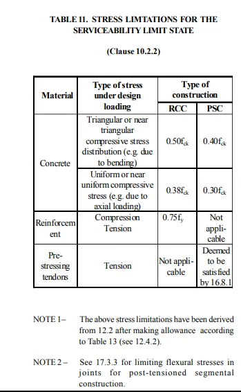
To determine specific stress limitations for SLS in PSC and RCC pier caps, we typically refer to applicable design codes and standards. In the case of PSC, standards like AASHTO LRFD Bridge Design Specifications and ACI 318 (for the concrete portion) would be relevant. For RCC, standards like ACI 318 would be more applicable.
4.Explain the allowable crack width limit for a pier cap and explain the impact of design crack widths.
Allowable crack width limits for pier caps, or any concrete structure, are typically defined by engineering codes and standards. These limits are established to ensure the structural integrity, safety, and serviceability of the structure while taking into account factors such as durability, aesthetics, and functionality. The allowable crack width is usually specified in terms of a maximum width or opening that a crack can reach without compromising the performance of the structure.
The allowable crack width limit is influenced by several factors:
-
Serviceability: One of the primary considerations is maintaining serviceability, which includes factors like comfort, functionality, and long-term durability. Excessive crack widths can impact the functionality and appearance of a structure.
-
Corrosion Protection: Larger cracks can allow moisture and aggressive chemicals to penetrate deeper into the concrete, potentially reaching reinforcing steel. This can lead to corrosion of the steel, which can compromise the structure's strength and durability.
-
Aesthetics: Cracks that are too wide can be unsightly, and they may not meet the aesthetic requirements of the project.
-
Structural Integrity: While serviceability is a primary concern, the allowable crack width also considers the structural integrity of the pier cap. Very wide cracks can reduce the load-carrying capacity of the structure.
-
Environmental Conditions: The allowable crack width may vary depending on the environmental conditions to which the structure is exposed. Structures in harsh environments may have stricter crack width limits to ensure long-term durability.
The impact of design crack widths on a pier cap can be significant:
-
Serviceability: Larger cracks can affect the appearance and functionality of the pier cap and the entire structure. For example, if the pier cap is part of a bridge, wider cracks can lead to water infiltration, which can result in slippery conditions for vehicles and pedestrians. This can impact safety and comfort.
-
Durability: The wider the cracks, the greater the risk of moisture and aggressive substances penetrating the concrete. This can accelerate the deterioration of the pier cap and reduce its expected lifespan.
-
Aesthetics: In some cases, such as architectural structures or projects with high aesthetic requirements, wider cracks may be unacceptable from an appearance standpoint.
-
Maintenance Costs: If cracks exceed allowable limits, more frequent maintenance and repairs may be necessary to address both the structural and aesthetic concerns. This can increase the lifecycle cost of the structure.
-
Structural Performance: In extreme cases, very wide cracks can weaken the structural integrity of the pier cap, affecting its ability to carry loads safely. This could lead to the need for costly repairs or even structural failure.
To manage crack widths, we use various design and construction techniques, including proper concrete mix design, reinforcement strategies, control joint placement, and waterproofing measures. These techniques aim to control cracking and ensure that any cracks that do occur remain within allowable limits.
5.Why pier caps are designed as a cantilever section
Pier caps are often designed as cantilever sections for several engineering and structural reasons:
-
Load Distribution: Pier caps serve as the load-bearing elements that distribute the weight and forces from the superstructure (such as a bridge deck or beam) onto the supporting piers or columns. By designing pier caps as cantilevers, the load is transferred efficiently from the superstructure to the pier without excessive bending or deflection.
-
Structural Stability: Cantilevered pier caps provide structural stability to the overall bridge or elevated structure. The cantilever design resists lateral forces, such as wind loads and seismic forces, which helps maintain the stability of the entire structure.
-
Simplicity: Cantilevered pier caps are relatively simple to design, fabricate, and construct. This simplicity can reduce construction costs and construction time compared to more complex structural configurations.
-
Space Optimization: Cantilevered pier caps maximize the usable space between piers or columns. This is especially important in transportation infrastructure, where minimizing the width of the supporting elements allows for the efficient flow of traffic, such as vehicles, trains, or pedestrians.
-
Flexibility in Span: Cantilevered pier caps can accommodate various span lengths. By adjusting the dimensions and reinforcement of the cantilevered section, engineers can tailor pier caps to suit the specific span requirements of the project.
-
Load Transfer: Cantilevered pier caps provide a gradual transfer of loads from the superstructure to the supporting piers or columns. This gradual transfer minimizes stress concentrations and helps prevent structural issues like cracking or excessive deformation.
-
Design Efficiency: Cantilevered designs are efficient in terms of material usage. They distribute loads in a manner that minimizes the need for excessive concrete or reinforcement, optimizing the pier cap's design for strength and economy.
It is important to note that the design of cantilevered pier caps must consider factors such as the magnitude and distribution of loads, the pier or column geometry, and the soil conditions at the site.
6.What are the key elements considered in finalizing a pier cap length for a metro viaduct design?
The finalization of a pier cap length for a metro viaduct design involves considering several key elements to ensure the structural integrity, safety, and functionality of the viaduct. These elements typically include:
-
Span Length: The span length refers to the distance between two adjacent piers or supports. It is a fundamental parameter in pier cap design. The longer the span, the larger the required pier cap length to distribute the loads effectively. The span length is often determined based on the specific alignment and layout of the metro viaduct.
-
Load Analysis: Engineers must conduct a comprehensive load analysis to determine the various types of loads the pier cap will need to support. This includes the weight of the metro trains, live loads (passengers, equipment), wind loads, seismic loads, and any other relevant loads. The length of the pier cap should be designed to safely accommodate these loads.
-
Design Codes and Standards: Local building codes and design standards dictate the minimum requirements for structural elements, including pier caps. These standards provide guidelines for factors such as live load limits, load combinations, and design safety factors that impact the determination of pier cap length.
-
Materials and Construction Techniques: The choice of materials (typically reinforced concrete or prestressed concrete) and construction techniques can influence the design of the pier cap. The specific properties of the chosen materials and the construction method will affect the structural behavior and performance of the pier cap.
-
Geotechnical Conditions: The characteristics of the soil or foundation upon which the piers and pier caps are built are crucial. Geotechnical studies provide information on factors like soil bearing capacity, settlement characteristics, and the need for foundation improvements (e.g., pile foundations). The length of the pier cap should be designed to accommodate the foundation system.
-
Aesthetic and Architectural Considerations: In some cases, the design of the metro viaduct may have aesthetic or architectural requirements. The length and shape of the pier cap should align with these design considerations while still meeting structural and safety requirements.
-
Maintenance and Accessibility: Accessibility for maintenance and inspection is essential. The design should allow for safe access to the pier caps for routine inspections, maintenance, and repair work.
-
Expansion and Contraction: Temperature variations can cause concrete structures to expand and contract. Engineers need to account for thermal effects when determining the length of the pier cap to prevent issues like cracking.
-
Alignment and Alignment Changes: The alignment of the metro viaduct, including any curves or changes in direction, can impact the design of the pier caps. The length may need to be adjusted to accommodate these changes.
-
Future Expansion: Consideration should be given to the potential for future expansion or modifications to the metro system. This may require designing pier caps with additional capacity to support future loads or changes in alignment.
The finalization of pier cap length is a complex engineering process that involves a combination of structural analysis, geotechnical investigation, adherence to design codes, and coordination with architectural and functional requirements.
7.What are the key elements considered in designing the drainage arrangement of a pier cap for a metro viaduct?
Designing the drainage arrangement for a pier cap in a metro viaduct is essential to prevent water accumulation, corrosion, and other potential issues that can compromise the structural integrity and durability of the pier cap and the entire viaduct. Key elements considered in designing the drainage arrangement for a metro viaduct pier cap include:
-
Surface Slope: The surface of the pier cap should be designed with a slight slope to encourage water runoff. This slope ensures that rainwater and other surface water do not pool or accumulate on the pier cap's surface.
-
Scuppers or Drainage Openings: Scuppers or drainage openings are strategically placed openings or channels designed to allow water to flow away from the pier cap. These openings should be properly sized and positioned to efficiently drain water and prevent blockages.
-
Gutter Systems: In some cases, gutter systems or channels can be incorporated into the design of the pier cap to collect and redirect water away from the structure. These gutters should be designed to handle expected rainfall and surface water runoff.
-
Waterproofing: Waterproofing materials and membranes can be applied to the surface of the pier cap to provide an additional layer of protection against moisture penetration. Proper waterproofing can help extend the life of the structure and reduce the risk of corrosion.
-
Drainage Pipes: Depending on the design and site conditions, drainage pipes may be installed beneath or within the pier cap to collect and channel water away from the structure. These pipes should be properly sized and connected to the overall drainage system.
-
Anti-Corrosion Measures: To protect any reinforcing steel or prestressing tendons within the pier cap, anti-corrosion measures may be necessary. This can include the use of corrosion-resistant materials, coatings, or cathodic protection systems.
-
Drainage System Maintenance: Adequate access and provisions for maintenance of the drainage system should be considered. Regular inspection and cleaning of scuppers, gutters, and drainage pipes are essential to ensure that the system functions effectively over time.
-
Environmental Considerations: The design should take into account potential environmental impacts, such as the discharge of water into local water bodies. Compliance with environmental regulations and permitting requirements is crucial.
-
Freeze-Thaw Considerations: In regions with cold climates, special attention should be given to preventing the accumulation of water that can freeze and expand, potentially causing damage to the pier cap. Proper drainage and insulation measures are important in these areas.
-
Quality Control: Quality control measures should be in place during construction to ensure that drainage elements are installed correctly and that waterproofing materials are applied according to specifications.
-
Hydraulic Considerations: Engineers need to consider the hydraulic characteristics of the drainage system, ensuring that it can handle peak rainfall events without causing flooding or excessive water flow.
-
Safety: Safety features, such as guardrails or covers for drainage openings, should be incorporated to prevent accidents or debris blockages.
-
Integration with Surrounding Infrastructure: The drainage system of the pier cap should be integrated with the broader drainage network of the metro viaduct to ensure seamless water flow and prevent localized flooding.
Properly designed drainage arrangements are critical for maintaining the long-term durability and safety of metro viaduct pier caps.
8.What are the key elements considered in finalizing a pier cap width for a metro viaduct design?
Finalizing the width of a pier cap in a metro viaduct design involves considering several key elements to ensure the structural integrity, safety, and functionality of the pier cap and the entire viaduct. These elements typically include:
-
Number of Tracks and Spans: The number of railway tracks or lanes the viaduct needs to accommodate directly influences the width of the pier cap. Each track typically requires a certain minimum width to accommodate the railway infrastructure, including rails, track beds, and any required clearances.
-
Load Analysis: Engineers must conduct a comprehensive load analysis to determine the various types of loads the pier cap will need to support. This includes the weight of the metro trains, live loads (passengers, equipment), wind loads, seismic loads, and any other relevant loads. The width of the pier cap should be designed to safely accommodate these loads.
-
Design Codes and Standards: Local building codes and design standards dictate the minimum requirements for structural elements, including pier caps. These standards provide guidelines for factors such as live load limits, load combinations, and design safety factors that impact the determination of pier cap width.
-
Track Alignment and Clearances: The alignment of the metro tracks and the required clearances for safe railway operation are critical. The width of the pier cap should allow for the proper alignment of tracks and any necessary clearances for train movements, including curves and switches.
-
Platform Width and Accessibility: The width of the pier cap must also consider the width of passenger platforms, ensuring that there is sufficient space for safe passenger boarding and alighting. Accessibility requirements, such as ramps or elevators, may also impact the width of the pier cap.
-
Emergency Egress: Provisions for emergency egress routes and access for emergency services should be incorporated into the design. This may require additional width for walkways or access paths.
-
Structural Integrity: The width of the pier cap should provide sufficient space for reinforcing steel, prestressing tendons, and any other structural elements necessary to support the loads and forces applied to the pier cap.
-
Aesthetic and Architectural Considerations: In some cases, the design of the metro viaduct may have aesthetic or architectural requirements that influence the width of the pier cap. Aesthetic elements such as railings, parapets, or architectural features may need to be accommodated.
-
Space Optimization: While ensuring structural integrity and safety, engineers aim to optimize the use of space between piers or columns. This is important for efficient traffic flow, minimizing the footprint of the viaduct, and ensuring that the structure fits within the urban or suburban environment.
-
Expansion and Contraction: Temperature variations can cause concrete structures to expand and contract. Engineers need to account for thermal effects when determining the width of the pier cap to prevent issues like cracking.
-
Future Expansion: Consideration should be given to the potential for future expansion or modifications to the metro system. This may require designing pier caps with additional width to support future tracks, platforms, or other infrastructure.
The finalization of pier cap width is a complex engineering process that involves a combination of structural analysis, alignment considerations, adherence to design codes, and coordination with architectural and functional requirements.
9.What is aesthetic requirements consideration of pier caps in a design of a metro viaduct?
Aesthetic requirements play a significant role in the design of pier caps for a metro viaduct, as they impact the visual appearance and integration of the viaduct into its surroundings. Aesthetic considerations aim to ensure that the metro viaduct is not only functional but also harmonious with its urban or suburban environment. Here are some key aesthetic requirements and considerations for pier caps in the design of a metro viaduct:
-
Architectural Style: The architectural style of the pier caps should be consistent with the overall design theme of the metro viaduct and its surroundings. Whether the viaduct is in a historic, modern, or futuristic context, the pier caps should reflect the chosen architectural language.
-
Materials and Finishes: The choice of materials and finishes for the pier caps is crucial for aesthetics. Materials such as concrete, stone, steel, or composite materials may be selected based on their appearance and how they complement the architectural style. Surface finishes can include textures, colors, and patterns.
-
Proportions and Scale: The proportions and scale of the pier caps should be visually pleasing and proportionate to the size of the viaduct and the surrounding urban context. Oversized or undersized pier caps can disrupt the visual balance of the structure.
-
Ornamental Details: Ornamental elements, such as decorative moldings, sculptures, or reliefs, can be incorporated into the pier caps to enhance their aesthetic appeal. These details should be designed with care to add character without overwhelming the structure.
-
Railing and Parapet Design: If railings or parapets are part of the pier cap design, their aesthetics should align with the overall design theme. The railings can include decorative elements or patterns that contribute to the viaduct's visual identity.
-
Lighting: Consideration should be given to the integration of lighting elements into the pier caps. Well-designed lighting can enhance the viaduct's appearance at night and contribute to safety and ambiance.
-
Color Selection: The choice of colors for the pier caps should complement the surrounding environment and any adjacent buildings or infrastructure. Color can be used to create visual harmony or contrast as desired.
-
Environmental Integration: The pier caps should be designed to fit seamlessly into the natural landscape, urban setting, or architectural context. This may involve incorporating landscaping elements or greenery around the piers.
-
Historical Preservation: In historic districts or areas with cultural significance, pier cap designs should respect and preserve the historical character of the surroundings. Historic preservation guidelines and approvals may be required.
-
Community Engagement: Public input and community feedback can be valuable in shaping the aesthetic design of the pier caps. In some cases, community preferences and cultural considerations can influence the final design.
-
Maintenance and Durability: Aesthetic elements should be chosen with consideration for long-term maintenance and durability. Materials and finishes should be selected to withstand environmental conditions and the passage of time.
-
Regulatory Approvals: Depending on the jurisdiction, regulatory authorities may have specific guidelines and approval processes for the aesthetic design of transportation infrastructure, including pier caps. Compliance with these regulations is essential.
Balancing aesthetic requirements with structural and functional considerations is a complex task that requires collaboration between architects, urban planners, engineers, and other stakeholders. The goal is to create metro viaducts with pier caps that not only serve their practical purposes but also contribute positively to the visual character and quality of the urban or suburban environment in which they are situated.