Challenge 6 : Concept Modeling of Side Fender
Concept modelling of Car Side Fender
Objective
To create a proper curve network and further develop surfaces to create the front fender of a car.
Introduction
Fender is the American English term (referred to as “wing” in British English) for the part of an automobile, motorcycle or other vehicle body that frames a wheel. Its primary purpose is to prevent sand, mud, rocks, liquids, and other road spray from being thrown into the air by the rotating tire. Fenders are typically rigid and can be damaged by contact with the road surface. The equivalent component of a bicycle or motorcycle, or the "cycle wing" style of wing fitted to vintage cars, or over tires on lorries which is not integral with the bodywork, is called a mudguard in Britain, as it guards other road users – and in the case of a bicycle or motorcycle, the rider as well – from mud, and spray, thrown up by the wheels.
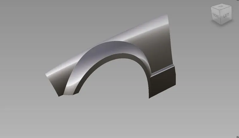
This project involves concept modelling of front fender of GMC Sierra. Also, as an additional design work, the front fender of American muscle Ford Mustang is done. This project was designed in Autodesk’s Alias AutoStudio 2021.
Design methodology / approach
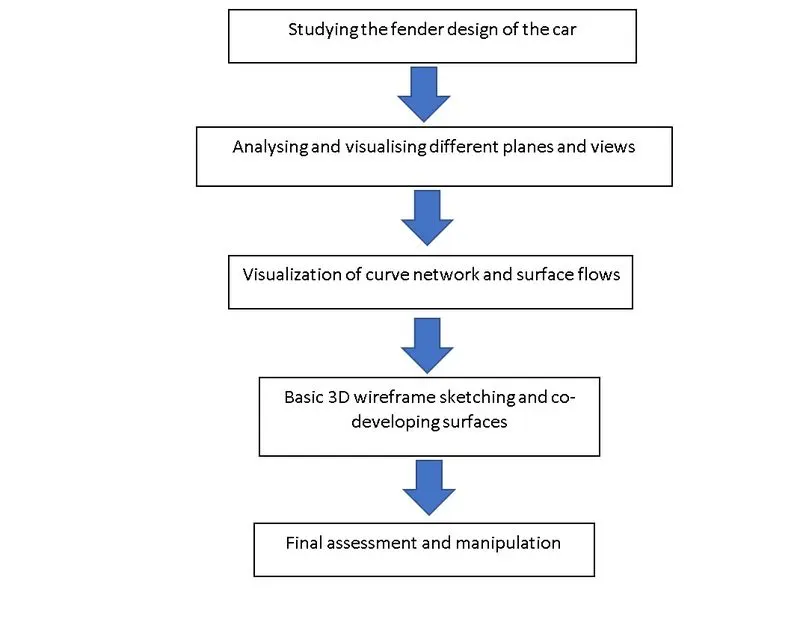
Description of features/tools used
Concepts Involved:
- Importing model design canvas of the fender
- Adding canvas to layers
- Tracing the curves using basic curve functions and utilities
- Visualizing and manipulating curves structures to obtain proper surfaces.
- Generating symmetries.
Features used:
1.Various pick options:
- Pick object
Used to pick and place objects from one place to another.
- Pick nothing
Used to unselect previously selected objects, components, curves etc...,
- Pick Curves
Used to specifically pick curves
- Pick blend points
Used to pick blend points in the workspace.
2. Some Transform options
- Move
Used to move around selected objects, curves etc...,
- Rotate
Used to rotate selected items about a point.
- Scale
Used to scale up/down the size of selected items.
- Snap
It's essentially not a transformation tool yet comes very handy. It's used to snap desired items to particular an object, a curve or a point.
3. Curves options
- cv, ep curves
Used to draw curved features.
- Blendcrv tools (new, edit)
Used to blend to lines/curves to form a single entity. Blends can be edit to achieve optimum accuracy.
- Keypoint curve box (Ellipse, arc, line, drag)
Contains tools like Ellipse, arc, line, drag which comes handy while drawing.
4. Features associated with layers and canvas.
- Attaching canvases to layers.
- Hiding and unhiding canvases using hide/unhide functionality in layers.
5. Surface generation features
- Rail
This surface creation tool is used when there are generation and rail curves available. Depending upon the no. of generation, rail curves present, one can easily toggle among for more appropriate versions of rail tool and generate surfaces.
- Square
This is another surface generation tool that comes very handy. This tool can be used when surfaces are to be generated within 4 bounding curves.
- Skin
To build a surface bridging two curves
- Ffblend
This feature is primarily used to bridge surfaces.
- Srfillet
This feature is used to add fillets betwwen two edges.
6. Surface edit tools
- Project
Project tool can be used to project curves onto surfaces which can be later used for trimming purposes.
- Intersect
This tool is similar to project tool but used to project surfaces and objects.
- Trim
This option is used to trim away parts that are unnecessary. This tool can be used only after project/intersecting curves or bodies onto surfaces that are later trimmed/altered.
- Trimcvt
This feature is similar to trim function except for its ability to reorient the CVs of the trimmed surface.
7. Object edit tools
- Align
This feature can be used to align curves/surfaces to form continuous flowing entities.
- Attach/detach
This feature is used for attaching/detaching two surfaces or curves.
- Extend
This feature is used to extend or lessen the cross sections of curves or surfaces.
- Qryed
This feature takes us back to the feature that’s been previously applied to the selected object.
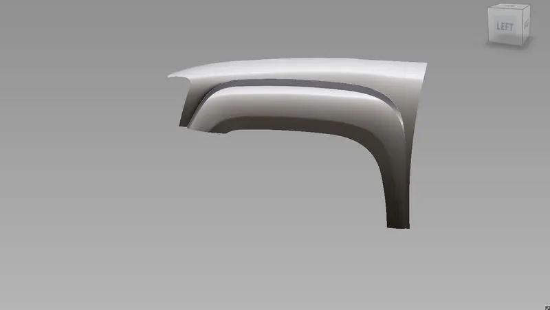
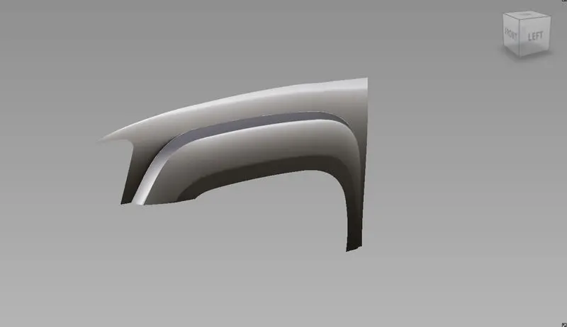
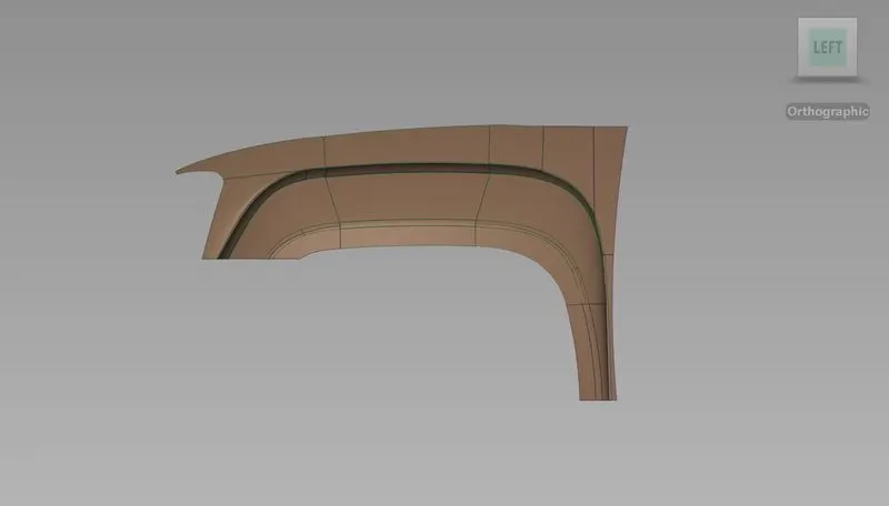
Images of Side Fender models:
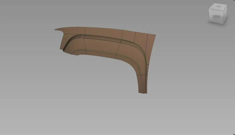
Side Fender of GMC Sierra 1500
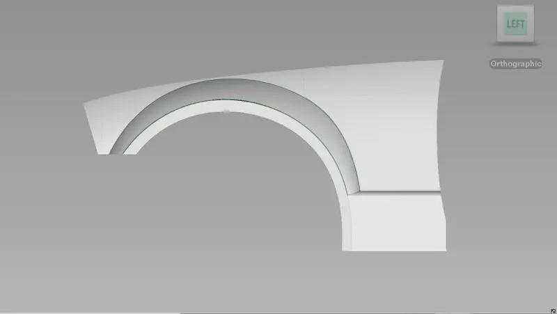
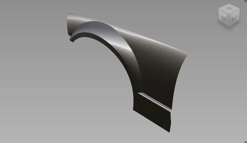
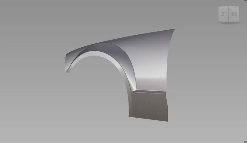
Side Fender of Ford Mustang 2005
Conclusion
Working on this project gave insights of how to go about designing the car fenders using a single view and visualizing the rest. Interpreting 2D design blue prints and converting them to 3D curve structures gave understanding of different views and planes. Practised the basics concepts of continuities in curves and surfaces. Ventured through different features and approaches of design in Alias.